November 22, 2013 at 17:47
The mathematical model of Lego Segway
- Tutorial
Good afternoon, dear colleagues. This article will be a continuation of the topic started in the post habrahabr.ru/post/178103 .
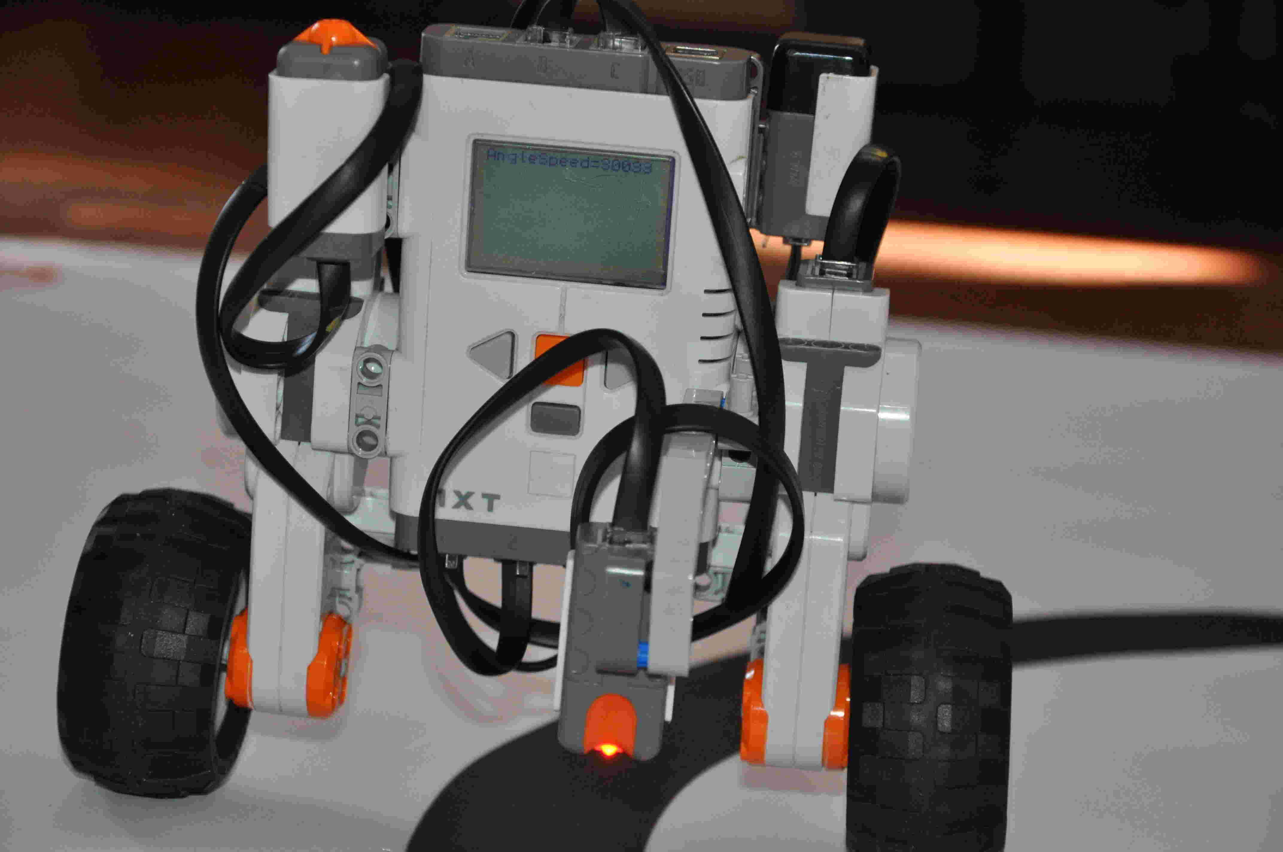
We continue from the moment when we already have the values of the structural constants for the Lego engine, and we can proceed to the design and calculation of the robot. As a prototype, let's dwell on the Segway. This is one of the most significant tasks of the theory of automatic control. I give the design of this mechanism.
To begin, let us dwell on the derivation of the mathematical model of our robot. We choose the generalized coordinates as follows:
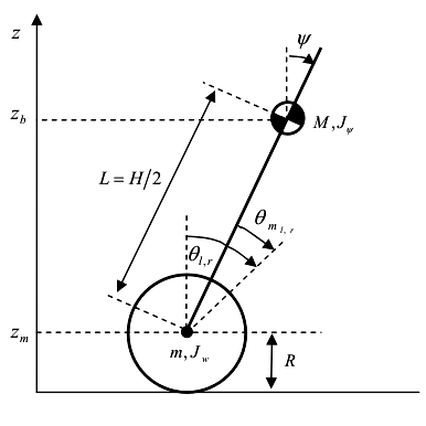
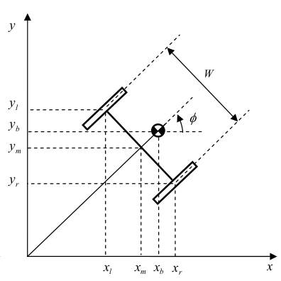
All designations of masses and momenta of inertia are presented in the figure. It is assumed that our robot moves only in one XOZ plane. We will consider Segway, as an integral brick, without separately calculating the moments of inertia of the engines and wheels, to reduce the size of the equations of the system.
We write the equations of the coordinates of the center of mass of the system:


Now we calmly write the equation for the Lagrangian:

To automate the calculations, we use the Maxima symbolic calculation system and its WxMaxima graphical environment. Enter the resulting expression on the command line:
The command \ verb | trigsimp | used to simplify trigonometric expressions, and \ verb | expand | to open the brackets. Team \ verb | tex | allows you to translate the result into a tex-format, which will allow you to display the formulas in a tex-document or in the form of drawings.

We write the derivatives in a compact form, we obtain the following equation:

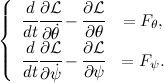
And we write the Lagrange equation as follows:
Program for Maxima:
After completing the indicated actions, we get:



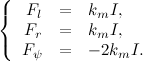
Next, we compose the equations for the engines of our Segway, using the material from the previous post habrahabr.ru/post/178103 :


Since the inductance of the winding is extremely small, put L = 0:

We get:

Now we equate our moment equations, leaving the left side only elements with control voltage:

In order to use the equation for calculating the matrix of feedback coefficients, we linearize the resulting model. We will use the first remarkable limit, substitute and
and  . We will also neglect the remaining non-linearities:

Now we can write the resulting equations in matrix form by accepting :
:


For us, this is an unusual form, so from these matrices we need to glue two matrices, the state matrix of our system and the control matrix. To do this, we expand the state variable by adding another equation:
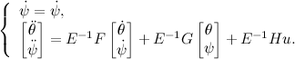

Now, we have obtained a third-order system and we know all the dynamics and reaction to control actions. In order to make it stable, we must write matrices describing a knownly stable system. We use for this Newton’s binomial where
where  . Here is the
  tabular value of the transition time of the reference model,
  the transition time of the model of our robot, which we took equal to 0.3 seconds. Having compiled a reference model, calculating its eigenvalues
 , you can apply Ackerman's formula to calculate the feedback coefficients:



But not everything is as smooth as we would like. The obtained coefficients will most likely not be working, since we did not impose restrictions on the control voltage, although it is only 7 [V]. To fix this, you will have to simulate the system and reduce the coefficients for the angular velocities of the pendulum and the wheels of the robot.

The blue line will be the most suitable for us in terms of the ratio of overshoot and transition time. After that, we get a working program for the robot.
We continue from the moment when we already have the values of the structural constants for the Lego engine, and we can proceed to the design and calculation of the robot. As a prototype, let's dwell on the Segway. This is one of the most significant tasks of the theory of automatic control. I give the design of this mechanism.
To begin, let us dwell on the derivation of the mathematical model of our robot. We choose the generalized coordinates as follows:
All designations of masses and momenta of inertia are presented in the figure. It is assumed that our robot moves only in one XOZ plane. We will consider Segway, as an integral brick, without separately calculating the moments of inertia of the engines and wheels, to reduce the size of the equations of the system.
We write the equations of the coordinates of the center of mass of the system:
Now we calmly write the equation for the Lagrangian:
To automate the calculations, we use the Maxima symbolic calculation system and its WxMaxima graphical environment. Enter the resulting expression on the command line:
V:expand(
    trigsimp(
        ((diff(integrate(R*diff(Theta(t),t),t)+L*sin(Psi(t)),t))^2+
        (diff(R+L*cos(Psi(t)),t))^2)*M/2
        +J2*(diff(Psi(t),t))^2/2-M*g*(R+L*cos(Psi(t)))
    )
);
tex(V);
The command \ verb | trigsimp | used to simplify trigonometric expressions, and \ verb | expand | to open the brackets. Team \ verb | tex | allows you to translate the result into a tex-format, which will allow you to display the formulas in a tex-document or in the form of drawings.
We write the derivatives in a compact form, we obtain the following equation:
And we write the Lagrange equation as follows:
Program for Maxima:
U:expand(diff(diff(V,diff(Ttheta(t),t)),t)-diff(V,Theta(t)));
Y:expand(diff(diff(V,diff(Psi(t),t)),t)-diff(V,Psi(t)));
tex(U);
tex(Y);
After completing the indicated actions, we get:
Next, we compose the equations for the engines of our Segway, using the material from the previous post habrahabr.ru/post/178103 :
Since the inductance of the winding is extremely small, put L = 0:
We get:
Now we equate our moment equations, leaving the left side only elements with control voltage:
In order to use the equation for calculating the matrix of feedback coefficients, we linearize the resulting model. We will use the first remarkable limit, substitute
and . We will also neglect the remaining non-linearities: Now we can write the resulting equations in matrix form by accepting
:For us, this is an unusual form, so from these matrices we need to glue two matrices, the state matrix of our system and the control matrix. To do this, we expand the state variable by
adding another equation: Now, we have obtained a third-order system and we know all the dynamics and reaction to control actions. In order to make it stable, we must write matrices describing a knownly stable system. We use for this Newton’s binomial
where . Here is the tabular value of the transition time of the reference model, the transition time of the model of our robot, which we took equal to 0.3 seconds. Having compiled a reference model, calculating its eigenvalues, you can apply Ackerman's formula to calculate the feedback coefficients: But not everything is as smooth as we would like. The obtained coefficients will most likely not be working, since we did not impose restrictions on the control voltage, although it is only 7 [V]. To fix this, you will have to simulate the system and reduce the coefficients for the angular velocities of the pendulum and the wheels of the robot.
The blue line will be the most suitable for us in terms of the ratio of overshoot and transition time. After that, we get a working program for the robot.
#define GYRO_PORT    IN_1
#define LEFT_MOTOR   OUT_C
#define RIGHT_MOTOR  OUT_B
#define BOTH_MOTORS  OUT_BC
#define WAIT_TIME    8.0
#define KGYROANGLE   0.487
#define KSPEED       0.024
#define KGYROSPEED   0.153
#define KPOS         0
task main(){
    float time = WAIT_TIME * 0.001;
    float segway_angle = 0;
    float segway_speed;
    float wheel_angle = 0, last_wheel_angle;
    float wheel_speed;
    float max_voltage;
    int u;
    SetSensorHTGyro(GYRO_PORT);
    Wait(50);
    while(true) {
        max_voltage = BatteryLevel() / 1000;
        segway_speed = (SensorHTGyro(GYRO_PORT) + 2);
        segway_angle += segway_speed * time;
        last_wheel_angle = wheel_angle;
        wheel_angle = (MotorRotationCount(LEFT_MOTOR) + MotorRotationCount(RIGHT_MOTOR)) / 2;
        wheel_speed = (wheel_angle - last_wheel_angle) / time;
        u = KGYROANGLE * segway_angle +
            KSPEED * wheel_speed +
            KGYROSPEED * segway_speed +
            KPOS * wheel_angle;
        u = u * 100 / max_voltage;
        if (abs(u) > 100){
            u = sign(u) * 100;
        }
        OnFwd(BOTH_MOTORS, u);
        Wait(WAIT_TIME);
    }
}