August 27, 2013 at 20:29
STM32 + EmBlocks - blinking LEDs
As requested in the comments on the previous article about EmBlocks, today I will show you from beginning to end how to create a simple project in EmBlocks for blinking a pair of LEDs.
As a debug board, we will use the chips on the STM32F103C8 .
Here is our stand: We
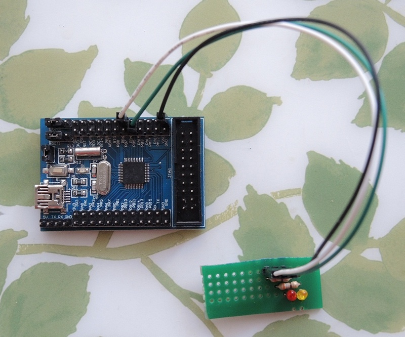
connect the anodes of the LEDs to the pins PB5 and PB6, the cathodes through 390 Ohm resistors to the ground.
So, if you have not downloaded EmBlocks yet , do it. Unzip to any convenient directory and run.
We create a project by choosing “File-> New-> Project ...” from the menu.
In the Projects category, select “STmicro-Arm”.
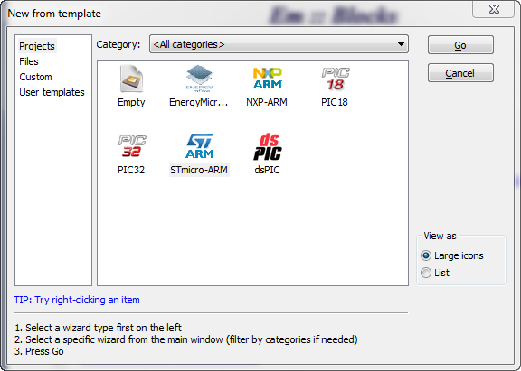
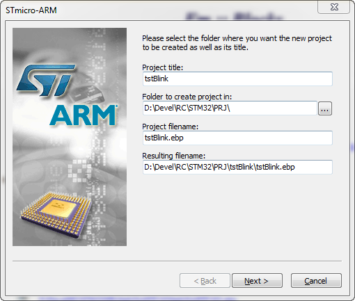
We name the project and select the folder in which it will be created. In the future, new projects will be automatically saved there, if you do not choose another.
In the compiler selection window, do not touch anything and move on.
In the processor selection window from the first list, select "STM32F10x_md" because STM32F103C8 belongs to the F1 family and contains 64k FLASH, which relates it to medium density devices.
If you will use ColinkEx, then in the next window we select the specific processor name, this is necessary for the CoFlash utility firmware.
If you use ST-Link, you can leave it alone.
The “Create hex file” checkbox is responsible for creating the .hex output instead of the .elf file. ColinkEx accepts both, but ST-Link Utility only .hex
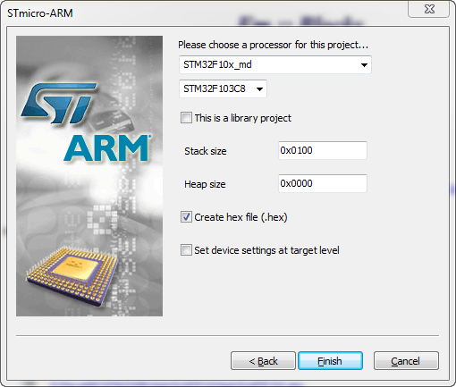
Click Finish. The wizard prompts you to select a debugger and configure it. And twice - for the purpose of Debug, and then for Release ... If you use another, click cancel and select another debugger. I’ll talk about other debuggers some other time.
By default, ST-Link is proposed, it suits us, so just click Ok twice for each goal (Debug, Release)
That's it, the project blank is ready. If you now press F7, the project will compile and is ready for firmware with a reminder, which is already taken into account in the settings of the Release target.
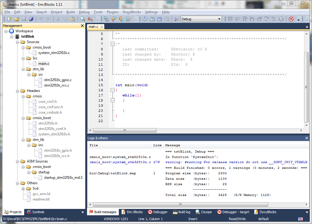
All project files are automatically decomposed into the Sources , Headers and ASM Sources folders for .c , .h and .S files, respectively.
In the Sources folder , we have a cmsis_boot subfolder with the CMSIS library file.
In the subfolder stm_lib \ src we already have a couple of files that are needed in almost any project: These are parts of the StdPeriph Library for working with GPIO and the clock system. The main.c file is located in the Src subfolder - a blank for our program. In the Headers folder
headers arranged in exactly the same folders.
In the future, we will add the necessary parts of the StdPeriph Library to the stm_lib \ inc and stm_lib \ src subfolders and include them in the project by right-clicking on the name and selecting “Add files ...” or “Add files recursively ...”. But today we don’t need it.
The startup_stm32f10x_md.S file, in the ASM Sources \ cmsis_boot \ startup folder, is responsible for starting the microcontroller .
The linker script lies in the Others folder and is called gcc_arm.ld
We briefly got acquainted with the structure of the project, it is time to write the code for which we started the business.
We open the file Sources \ Src \ main.c and replace the text in it with the following:
We defined the macros RCC_GPIO, LED_PORT, LED_PIN1 and LED_PIN2, changing which we can connect the LEDs to the pins of another port.
In the main () function, fill in the GPIO_InitStructure structure, setting the PB5 and PB6 pins to work in PushPull mode with a maximum frequency of 50MHz.
Then we invert the LED_PIN2 state so that the LEDs blink and in the cycle switch them with a slight delay.
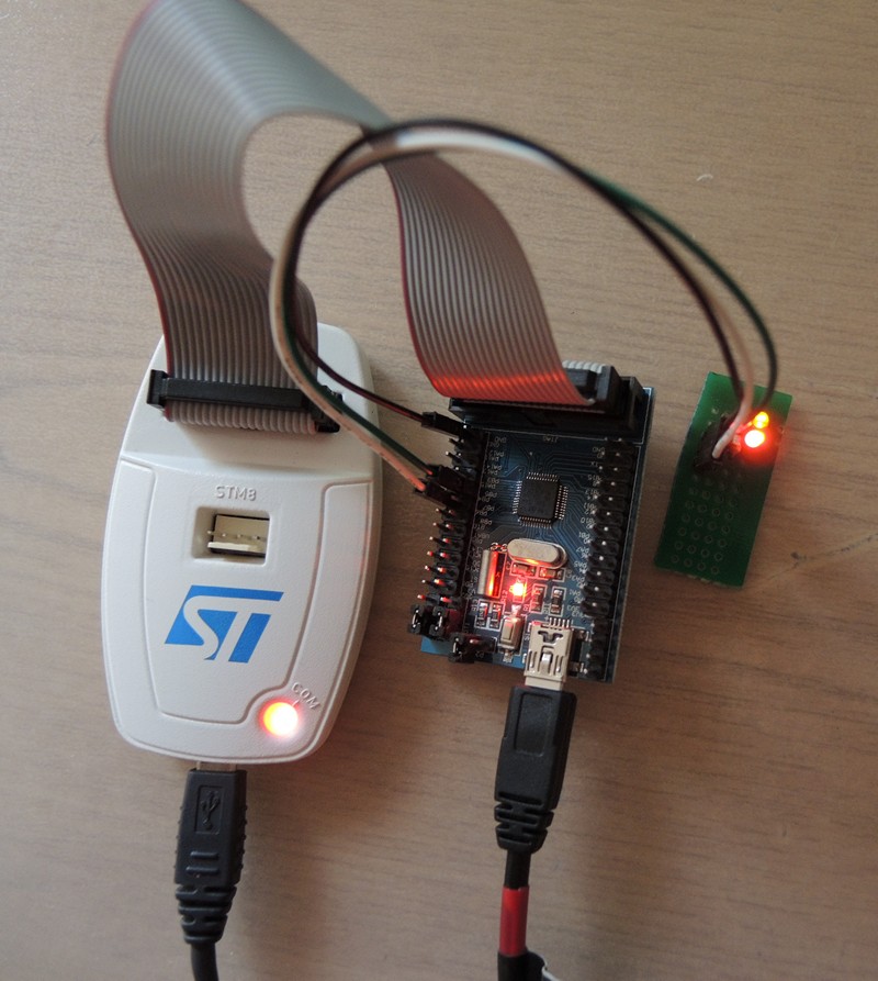
We press F7 , we make sure that the project was assembled without errors. We connect the ST-Link / v2 debugger to the board and supply power to it, for example via USB, by removing the P2 jumper so that the PC does not try to identify the board as a USB device, but simply provides power. Click F6

to flash using ST-Link / V2 or select “Tools-> Flash w ST-Link / V2” we wait a few seconds and if everything is done correctly, the LEDs will blink alternately, which is what we were aiming for:
Quite simply, isn’t it?
The whole process takes about a minute. If you still didn’t succeed, download the project and compare with what happened with you.
For another board, only the processor selection from the list will change if it differs and the macro definitions of the LEDs if it is connected to another port.
For example, for STM32VLDiscovery:
As a debug board, we will use the chips on the STM32F103C8 .
Here is our stand: We
connect the anodes of the LEDs to the pins PB5 and PB6, the cathodes through 390 Ohm resistors to the ground.
So, if you have not downloaded EmBlocks yet , do it. Unzip to any convenient directory and run.
We create a project by choosing “File-> New-> Project ...” from the menu.
In the Projects category, select “STmicro-Arm”.
We name the project and select the folder in which it will be created. In the future, new projects will be automatically saved there, if you do not choose another.
In the compiler selection window, do not touch anything and move on.
In the processor selection window from the first list, select "STM32F10x_md" because STM32F103C8 belongs to the F1 family and contains 64k FLASH, which relates it to medium density devices.
If you will use ColinkEx, then in the next window we select the specific processor name, this is necessary for the CoFlash utility firmware.
If you use ST-Link, you can leave it alone.
The “Create hex file” checkbox is responsible for creating the .hex output instead of the .elf file. ColinkEx accepts both, but ST-Link Utility only .hex
Click Finish. The wizard prompts you to select a debugger and configure it. And twice - for the purpose of Debug, and then for Release ... If you use another, click cancel and select another debugger. I’ll talk about other debuggers some other time.
By default, ST-Link is proposed, it suits us, so just click Ok twice for each goal (Debug, Release)
That's it, the project blank is ready. If you now press F7, the project will compile and is ready for firmware with a reminder, which is already taken into account in the settings of the Release target.
Let's analyze the project structure:
All project files are automatically decomposed into the Sources , Headers and ASM Sources folders for .c , .h and .S files, respectively.
In the Sources folder , we have a cmsis_boot subfolder with the CMSIS library file.
In the subfolder stm_lib \ src we already have a couple of files that are needed in almost any project: These are parts of the StdPeriph Library for working with GPIO and the clock system. The main.c file is located in the Src subfolder - a blank for our program. In the Headers folder
stm32f10x_gpio.c

stm32f10x_rcc.c
headers arranged in exactly the same folders.
In the future, we will add the necessary parts of the StdPeriph Library to the stm_lib \ inc and stm_lib \ src subfolders and include them in the project by right-clicking on the name and selecting “Add files ...” or “Add files recursively ...”. But today we don’t need it.
The startup_stm32f10x_md.S file, in the ASM Sources \ cmsis_boot \ startup folder, is responsible for starting the microcontroller .
The linker script lies in the Others folder and is called gcc_arm.ld
We briefly got acquainted with the structure of the project, it is time to write the code for which we started the business.
We open the file Sources \ Src \ main.c and replace the text in it with the following:
#include
#include
#include
#include
#define RCC_GPIO RCC_APB2Periph_GPIOB
#define LED_PORT GPIOB
#define LED1_PIN GPIO_Pin_5
#define LED2_PIN GPIO_Pin_6
void Delay(volatile uint32_t nCount) {
	for (; nCount != 0; nCount--);
}
int main(void) {
	/* SystemInit() уже отработала в startup_stm32f10x_md_vl.S */
	GPIO_InitTypeDef GPIO_InitStructure;
	RCC_APB2PeriphClockCmd(RCC_GPIO, ENABLE);
	GPIO_InitStructure.GPIO_Pin = LED1_PIN | LED2_PIN;
	GPIO_InitStructure.GPIO_Mode = GPIO_Mode_Out_PP;
	GPIO_InitStructure.GPIO_Speed = GPIO_Speed_50MHz;
	GPIO_Init( LED_PORT , &GPIO_InitStructure);
	LED_PORT->ODR ^= LED2_PIN;
	while (1) {
		LED_PORT->ODR ^= LED2_PIN;
		LED_PORT->ODR ^= LED1_PIN;
		Delay(0x7FFFF);
	}
	return 0;
}
We defined the macros RCC_GPIO, LED_PORT, LED_PIN1 and LED_PIN2, changing which we can connect the LEDs to the pins of another port.
In the main () function, fill in the GPIO_InitStructure structure, setting the PB5 and PB6 pins to work in PushPull mode with a maximum frequency of 50MHz.
Then we invert the LED_PIN2 state so that the LEDs blink and in the cycle switch them with a slight delay.
We press F7 , we make sure that the project was assembled without errors. We connect the ST-Link / v2 debugger to the board and supply power to it, for example via USB, by removing the P2 jumper so that the PC does not try to identify the board as a USB device, but simply provides power. Click F6
to flash using ST-Link / V2 or select “Tools-> Flash w ST-Link / V2” we wait a few seconds and if everything is done correctly, the LEDs will blink alternately, which is what we were aiming for:
Quite simply, isn’t it?
The whole process takes about a minute. If you still didn’t succeed, download the project and compare with what happened with you.
For another board, only the processor selection from the list will change if it differs and the macro definitions of the LEDs if it is connected to another port.
For example, for STM32VLDiscovery:
#define RCC_GPIO RCC_APB2Periph_GPIOC
#define LED_PORT GPIOC
#define LED1_PIN GPIO_Pin_8
#define LED2_PIN GPIO_Pin_9