ARMs for the smallest
- Tutorial
A couple of days ago I published and then suddenly drafted an article about a plan to write about creating my OS for the ARM architecture. I did this because I received a lot of interesting reviews both on Habré and in G +.
Today I’ll try to approach the issue on the other hand, I’ll talk about how to program ARM microcontrollers using examples of increasing complexity, until we write our own OS or until I get bored. Or maybe we will jump over picking in Contiki, TinyOS, ChibiOS or FreeRTOS, who knows, there are so many different and interesting ones (and TinyOS also has its own programming language!).
So why ARM? Fiddling with 8-bit microcontrollers, although interesting, is soon annoying. In addition, development tools for ARM are run in by long experience and much more pleasant in work. At the same time, starting to blink LEDs on some kind of "evaluation board" is as simple as on Arduino.
A small digression into architecture
ARM is promoting a wonderful architecture that it successfully licenses, it’s really hard for me to imagine in which device there is no presence of this company's products. Your smartphone is guaranteed to have several cores based on the ARM architecture. There are a couple more in a modern laptop (and this is not even a CPU, but also an accompanying controller of some peripherals), a few more - in a car. They are also in other household things: microwaves and televisions.
This flexibility is achieved by the fact that in the most basic version, the ARM core is very simple. Now there are three varieties of this architecture. Applicationused in "general purpose" devices - as the main processor in a smartphone or netbook. This profile is the most feature-rich, there is also a full-fledged MMU (memory management module), the ability to execute Java bytecode instructions in hardware, and even support for DRM schemes. Microcontroller is the exact opposite of the application profile, used (suddenly!) For use in microcontrollers. Minimal power consumption and deterministic behavior are relevant here. And finally, real-timeIt is used as an evolution of the microcontroller profile for tasks where it is critical to have a guaranteed response time. All these profiles have been implemented in one or several Cortex cores, for example, Cortex-A9 is based on the application profile and is part of the processor in the iPhone 4S, and Cortex-M0 is based on the microcontroller profile.
Pieces of iron!
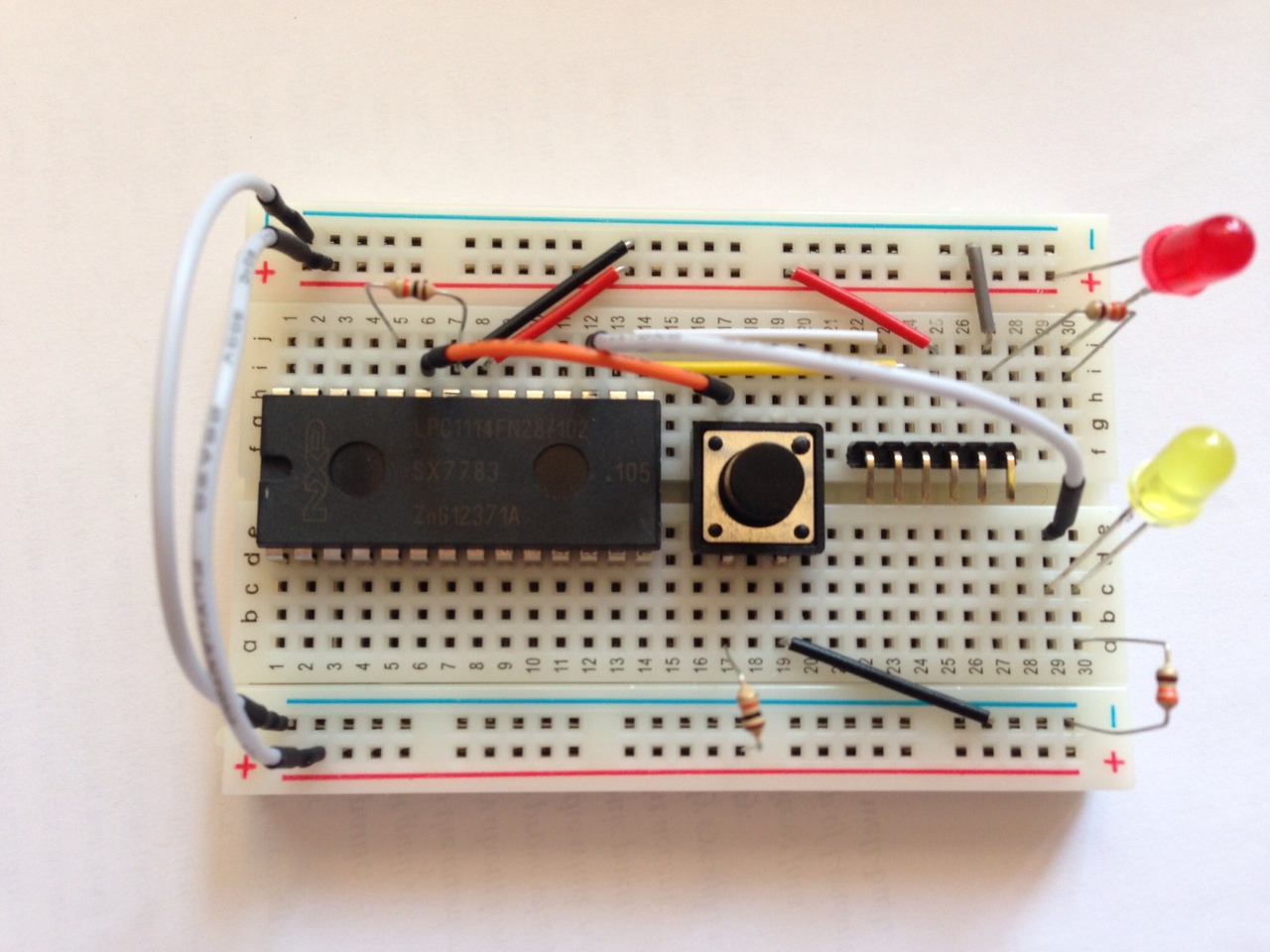
As a target platform, we will consider working with Cortex-M, since it is the simplest, respectively, we need to delve into fewer questions. As a test device, I offer you the LPC1114 - NXP MCU, a circuit on which you can assemble literally on your knee (no, however, you only need the MCU itself, a 3.3 V FTDI cable, several LEDs and resistors). LPC1114 is based on the Cortex-M0, so this will be the most stripped-down version of the platform.
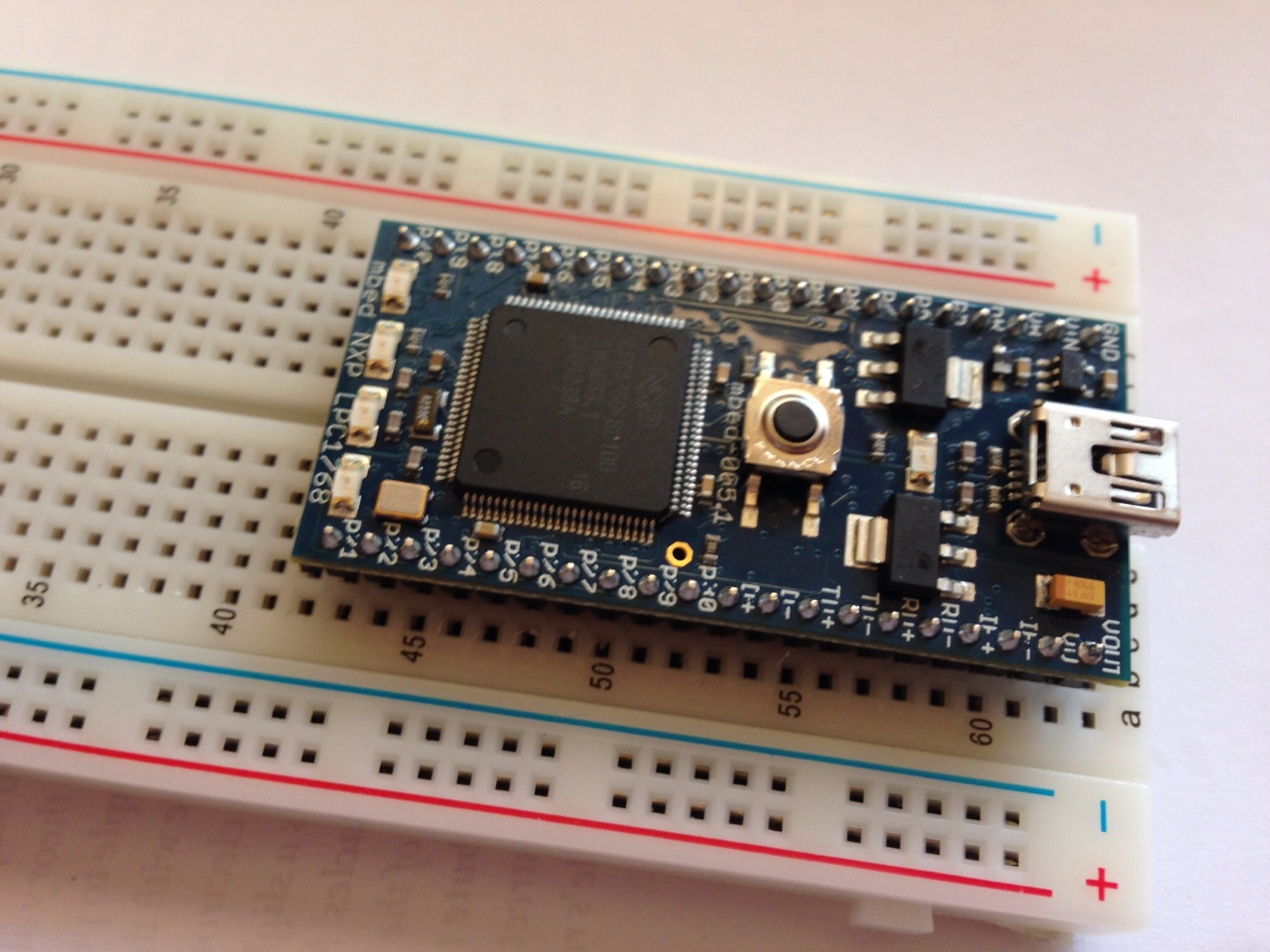
As an alternative, we will work with the mbed platform , and specifically, with the model based on LPC1768(which means that inside there Cortex-M3, a little more sophisticated). The option is already not so budgetary, but the process of uploading binaries to the chip and debugging is simplified as much as possible. Yes, and you can play around with the mbed platform itself (in short: this is an online IDE and a library with which you can program at the arduino level).
Let's get started
An interesting feature of modern ARMs is that they can be fully programmed entirely in C, without using assembler inserts (although assembler is not that complicated, Cortex-M0 has only 56 commands). Although some commands are not available from C in principle, CMSIS - Cortex Microcontroller Software Interface Standard solves this problem. This is a driver for a processor that solves all the basic tasks of managing it.
How does the processor load? A typical situation is when it simply starts to execute commands from the address 0x00000000. In our case, the processor is somewhat more intelligent, and relies on a specially defined data format at the beginning of the memory, namely, the table of interrupt vectors: The
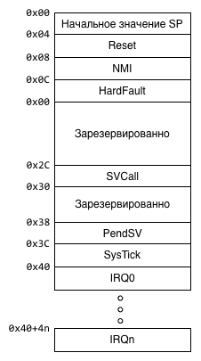
program starts as follows: the processor reads the value at 0x00000000 and writes it to SP (SP is a register that points to the top of the stack), after which it reads the value at 0x00000004 and writes it to the PC ( PC is a register that points to the current instruction + 4 bytes). Thus, some user code starts to be executed, while we already have a stack pointing somewhere in memory (i.e., all the conditions for executing a C program).
As a test exercise, we will blink the LED. On mbed we have four of them, in the circuit with LPC1114 (hereinafter referred to as the “board”) we install the LED manually.
Before writing the code directly, we need to find out one more thing, namely - what should be located in memory where. Since we are not working with some kind of “standard” OS, the compiler (or rather, the linker) cannot find out where it should have a stack, where the code itself, and where - a bunch. Fortunately for us, the Cortex family of cores has a standardized memory card, which makes it relatively easy to port applications between different processors of this architecture. Work with peripherals, of course, remains processor dependent.
The memory card for the Cortex-M0 looks like this:
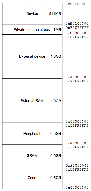
(image from the Cortex ™ -M0 Devices Generic User Guide )
At Cortex-M3, it is essentially the same, but somewhat more detailed. The problem here is that NXP has its own, separate view on this issue, so we check the memory card in the processor documentation:
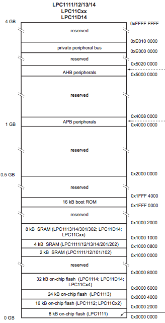
(image from LPC111x / LPC11Cxx User manual )
Actually, SRAM starts with 0x10000000! So, some standards, other standards, but you still need to scroll through the documentation volumes.
Armed with this knowledge, we are going to write code. For starters, an interrupt table:
.cpu cortex-m0      /* ограничиваем ассемблер списком существующих инструкций */
.thumb
.word   _stack_base /* начало стека в самом конце памяти, стек растет вниз */
.word   main        /* Reset: с прерывания сразу прыгаем в код на С */
.word   hang        /* NMI и все остальные прерывания нас не сильно волнуют */
.word   hang        /* HardFault */
.word   hang        /* MemManage */
.word   hang        /* BusFault */
.word   hang        /* UsageFault */
.word   _boot_checksum /* Подпись загрузчика */
.word   hang        /* RESERVED */
.word   hang        /* RESERVED*/
.word   hang        /* RESERVED */
.word   hang        /* SVCall */
.word   hang        /* Debug Monitor */
.word   hang        /* RESERVED */
.word   hang        /* PendSV */
.word   hang        /* SysTick */
.word   hang        /* Внешнее прерывание 0 */
                    /* ... */
/* дальше идут остальные 32 прерывания у LPC1114 и 35 у LPC1768, но
   их нет смысла описывать, потому как мы их все равно не используем */
.thumb_func
hang:   b .         /* функция заглушка для прерываний: вечный цикл */
.global hang
Save this table to
boot.s. Here, in fact, there is only one assembler insert - the hang function, which arranges an endless loop for the processor. All interrupts, except for reset, point to it, so in the event of an unforeseen situation, the processor will simply hang, and will not go to execute an incomprehensible piece of code. The table itself should be longer, but actually we could finish it even after the Reset vector, the rest would not work for us in this example. But, just in case, we filled the table almost entirely (except for user interrupts).
Now we write the implementation of the main function:
#if defined(__ARM_ARCH_6M__)
/* Cortex-M0 это ARMv6-M, код для LPC1114 */
#define GPIO_DIR_REG  0x50018000  /* GPIO1DIR  задает направление для блока GPIO 1 */
#define GPIO_REG_VAL  0x50013FFC  /* GPIO1DATA задает значение для блока GPIO 1 */
#define GPIO_PIN_NO   (1<<8)      /* 8-й бит отвечает за 8-й пин */
#elif defined(__ARM_ARCH_7M__)
/* Иначе просто считаем что это LPC1768 */
#define GPIO_DIR_REG  0x2009C020  /* FIO1DIR задает направление для блока GPIO 1 */
#define GPIO_REG_VAL  0x2009C034  /* FIO1PIN задает значение для блока GPIO 1 */
#define GPIO_PIN_NO   (1<<18)     /* 18-й бит отвечает за 18-й пин */
#else
#error Unknown architecture
#endif
void wait()
{
  volatile int i=0x20000;
  while(i>0) {
    --i;
  }
}
void main()
{
  *((volatile unsigned int *)GPIO_DIR_REG) = GPIO_PIN_NO;
  while(1) {
    *((volatile unsigned int *)GPIO_REG_VAL) = GPIO_PIN_NO;
    wait();
    *((volatile unsigned int *)GPIO_REG_VAL) = 0;
    wait();
  }
  /* main() *никогда* не должен вернуться! */
}
At mbed, the first LED is connected to the GPIO 1.18 port, on the board we connected the LED to GPIO 1.8. The same pins can perform different functions, these by default work just like GPIO (General Purpose I / O - General Purpose I / O Lines).
The code is relatively straightforward, if you keep at hand the LPC-shny User manual ( one and the second ). To begin with, we indicate the GPIO operating mode through the GPIO_DIR_REG register (on our processors they are in different places, and indeed the LPC1768 can work with GPIO more efficiently), where 1 is output, 0 is input. Then we start an endless cycle, in which we write to the port alternately the values 0 and 1 (0 V and 3.3 V, respectively).
The “pause” function works at random by simply scrolling a relatively long cycle (
volatile intit prevents the compiler from optimizing the whole cycle). Finally, all this needs to be put together correctly:
_stack_base = 0x10002000;
_boot_checksum = 0 - (_stack_base + main + 1 + (hang + 1) * 5);
MEMORY
{
   rom(RX)   : ORIGIN = 0x00000000, LENGTH = 0x8000
   ram(WAIL) : ORIGIN = 0x10000000, LENGTH = 0x2000
}
SECTIONS
{
   .text : { *(.text*) } > rom
   .bss  : { *(.bss*) } > ram
}
The linker script explains to him where we have the flash, where is the RAM, what sizes do they have (here the sizes for LPC1114 are used, since LPC1768 has the most, the shifts are, fortunately, identical). After determining the memory card, we indicate which segments where to copy, .text (program code) gets into the flash, .bss (static variables that we don’t have yet) - into memory. In addition, we specify two characters that were used in boot.s: _stack_base - indicates the top of the stack and _boot_checksum (thanks Zuyfor clarification!) - writes down the bootloader checksum. The check sum is calculated by the formula: an additional code (2's compliment) from the sum of the fields above (i.e. the address of the stack, and all interrupts to the check sum itself). Although the utilities for the firmware (see below) themselves would fix the checkbox to the correct one, if we were to flash the code from the application itself, then we would not be able to boot again.
Now we have three files: boot.s, main.c, mem.ld, it's time to compile it all and finally run it. We will use GCC as a tool chain, later, perhaps, I will show how to do the same with LLVM. OS X users, I advise you to take the toolchain from Linaro- at the very end of the list: Bare-Metal GCC ARM Embedded. For users of other OSs, I advise you to take the toolchain there :-) (unless it will be easier for gentushniks to save crossdev and compile GCC).
arm-none-eabi-as boot.s -o boot.o
arm-none-eabi-gcc -O2 -nostdlib -nostartfiles -ffreestanding -Wall -mthumb -mcpu=cortex-m0 -c main.c -o main-c0.o
arm-none-eabi-gcc -O2 -nostdlib -nostartfiles -ffreestanding -Wall -mthumb -mcpu=cortex-m3 -c main.c -o main-c3.o
arm-none-eabi-ld -o blink-c0.elf -T mem.ld boot.o main-c0.o
arm-none-eabi-ld -o blink-c3.elf -T mem.ld boot.o main-c3.o
arm-none-eabi-objdump -D blink-c0.elf > blink-c0.lst
arm-none-eabi-objdump -D blink-c3.elf > blink-c3.lst
arm-none-eabi-objcopy blink-c0.elf blink-c0.bin -O binary
arm-none-eabi-objcopy blink-c3.elf blink-c3.bin -O binary
An interesting point here is disabling the use of all standard libraries in GCC. Indeed, all the code that gets into the final binary is the code that we ourselves wrote.
Question: how does the linker know where to put the interrupt table? And he does not know, it is not written there :-). It just links in a row, starting from the zero address, so the order of the files (boot.o, then main-c0.o) is very important! Try linking the other way or linking boot.o twice and compare the output in the lst file.
A good idea is to look at the final listing (lst file) or drop the binary into the disassembler. Even if you don’t speak ARM UAL, then you can check visually that at least the interrupt table is in place:
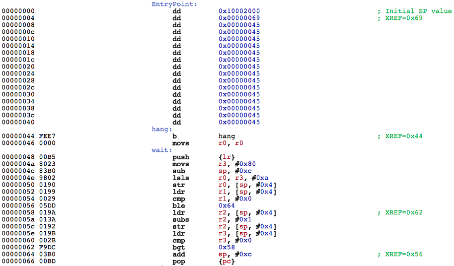
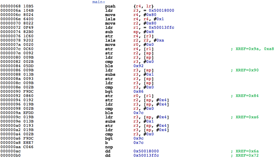
You can also pay attention to a funny moment - when compiling under Cortex-M3, GCC generates the wait () function more than in the version under Cortex-M0. True, if you enable optimization, then it will set his brains.
Blinking!
All that remains for us is to upload the binaries to our test platforms. With mbed, everything is as simple as possible, just copy
blink-c3.binto a virtual flash drive and press reset (on mbed). With a board everything is a little more complicated. First, in order to get into the bootloader, we need a resistor between GND and GPIO 0.1. Secondly, you need a program for direct firmware. You can use Flash Magic (Win, OS X), you can use the console utility - lpc21isp :lpc21isp.out -verify -bin /path/to/blink-c0.bin /dev/ftdi/tty/device 115200 12000
The firmware process is as follows:
- put a resistor between j5 and j7 (10 kOhm will do);
- press reset;
- we start lpc21isp;
- remove the resistor;
- press reset again - the application starts.
If you have the opportunity to run examples on different devices, you will notice that the blink speed on them is not identical. This is due to the fact that different devices have different core frequencies, respectively,
wait()they perform at different times. In the next part, we will study the oscillation issues in more detail and make a clear countdown. PS Special thanks to the pfactum habrayuzer for taking the time to correct my errors in the text :-).
PPS Request for those who have an ARM-based test platform - write in the comments - which one. I can review the hardware base for further articles.
Only registered users can participate in the survey. Please come in.
Are real hardware demos interesting?
- 35% I read, have / buy iron, I will run demos 424
- 17.7% I read, there is a similar hardware (ARM-based evaluation board) 215
- 4.1% Read, demos are not interesting 50
- 29.6% Scrolled, if there is a continuation - also scrolling 359
- 13.3% Didn’t read, but I like to vote 162
