How we ensure the resiliency of our customers' infrastructure
Good afternoon, dear Habrausers.
In this post, I would like to talk more about how we ensure the resiliency of our customers' infrastructure.
For example, we take a standard office (PC, IP-telephony, WiFi) with a breakdown into subsystems: ClientCloud, ClientLan, ClientPhone, ClientWiFi
The ClientLan subsystem is designed to provide PC access to other subsystems.
The ClientPhone subsystem is designed to provide IP phones with access to the ClientCloud subsystem (IP-PBX).
The ClientWiFi subsystem is designed to organize guest access of mobile equipment (laptops, communicators, tablet computers) to the Internet.
Access from the ClientWiFi subsystem to all subsystems (ClientCloud, ClientLan, ClientPhone) is prohibited by the switch settings.

In order to ensure fault tolerance of the equipment’s communication with the client’s cloud subsystem, two communication lines are provided: the primary (L2 channel) and the backup (VPN over the Internet). Equipment located on the LAN node in order to ensure uninterrupted operation of the network is connected to an uninterruptible power supply. To create a fault-tolerant system, the switches are stacked - Stacking Switch.
The LAN node at the Site includes:
-active equipment of the LAN switching level;
-passive port crossing equipment;
-passive equipment for arranging the placement of patch cords;
-passive installation equipment
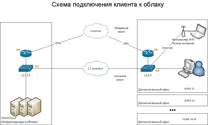
The object is connected to the network using two independent communication channels - L2 (main channel) and VPN via the Internet (backup). The logic diagram is shown in the figure. To ensure the highest fault tolerance, the L2 operators and the Internet operator are different, or independent (different) active equipment of the operator is used. Access to the Internet for PCs, printers, IP phones, Wi-Fi network devices and other devices occurs through this connection to the Internet.
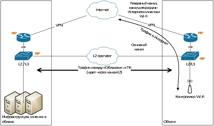
If the main channel L2 disappears, the routing table switches on the third-level switch, and the traffic begins to pass through the backup channel, the VPN channel. This switching occurs through the dynamic routing protocol RIP version 2.
If you lose a channel with Internet access, the main channel remains in operation. The ability to raise a backup VPN channel, as well as Internet access for PC users and Wi-Fi network devices, is no longer available.
The organization of the VPN channel takes place through the existing connection to the Internet through a telecom operator. A secure VPN is organized through hardware implementation using Cisco ASA5505 equipment using Site-to-site, IPsec technologies.
Switch Failover Scheme
Switches located in the server rack are stacked by StackingSwitch for fault tolerance. This is achieved by cross-connecting the stacking ports so that if any switch fails, the remaining ones will be available for each other along an alternative path. Connections of the external L2 network and the VPN channel are connected to different switches in order to maintain connection to the network when the switch fails. Switching the passage of traffic is fully automatic.
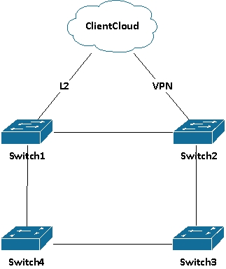
Access switches serve the following subsystems: ClientLan, ClientPhone, and ClientWiFi. Personal computers are connected to the switches Switch1 (Extreme Summit X440-48t) and Switch2 (Extreme Summit X440-48t). IP phones using PoE technology are switched on Switch3 and Switch4 (Extreme Summit X440-48p). The ClientWiFi subsystem on these switches is logically present and is connected via the Wi-Fi controller to the switch3 port of the switch.
Each subsystem has its own VLAN and its own subnet. Each subsystem has its own access list to other subnets (subsystems).
If one of the switches fails, only the PCs directly connected to this switch will lose communication without affecting the performance of the others. If Switch1 (or L2 channel) fails, communication with the ClientCloud subsystem will remain over the VPN channel. If Switch2 fails, the primary L2 channel will be used. When the Switch3 switch fails, some of the phones will turn off, however, by cross-connection it is stipulated that in one cabinet the phones are crossed to different Switch3 and Switch4 switches, and therefore the cabinet will not remain without communication, i.e. part of the phones will work.
After replacing the exited switch and putting it on the stack, a single stack configuration is applied to it. In the event of failure of the switches or ports to which the trunk lines are connected, partner ports are provided in the stack that allow manual switching of the trunk cable to resume operation through the necessary channel.
The scheme of connecting subsystems to switches
Thus, the client connection scheme is built so that each subsystem is allocated to its VLAN and its own subnet, which guarantees protection against the negative influence of one network on another (virus, heavy load) and provides access control over networks.

I would like to note that in each case, the client receives all the documentation with a detailed plan, connection diagram, equipment placement and cross-connection, which are necessary for maintenance and further modernization.
Ps Free test access with the advice of our technical experts is provided for all visitors to Habr.
In this post, I would like to talk more about how we ensure the resiliency of our customers' infrastructure.
For example, we take a standard office (PC, IP-telephony, WiFi) with a breakdown into subsystems: ClientCloud, ClientLan, ClientPhone, ClientWiFi
The ClientLan subsystem is designed to provide PC access to other subsystems.
The ClientPhone subsystem is designed to provide IP phones with access to the ClientCloud subsystem (IP-PBX).
The ClientWiFi subsystem is designed to organize guest access of mobile equipment (laptops, communicators, tablet computers) to the Internet.
Access from the ClientWiFi subsystem to all subsystems (ClientCloud, ClientLan, ClientPhone) is prohibited by the switch settings.
In order to ensure fault tolerance of the equipment’s communication with the client’s cloud subsystem, two communication lines are provided: the primary (L2 channel) and the backup (VPN over the Internet). Equipment located on the LAN node in order to ensure uninterrupted operation of the network is connected to an uninterruptible power supply. To create a fault-tolerant system, the switches are stacked - Stacking Switch.
The LAN node at the Site includes:
-active equipment of the LAN switching level;
-passive port crossing equipment;
-passive equipment for arranging the placement of patch cords;
-passive installation equipment
The object is connected to the network using two independent communication channels - L2 (main channel) and VPN via the Internet (backup). The logic diagram is shown in the figure. To ensure the highest fault tolerance, the L2 operators and the Internet operator are different, or independent (different) active equipment of the operator is used. Access to the Internet for PCs, printers, IP phones, Wi-Fi network devices and other devices occurs through this connection to the Internet.
If the main channel L2 disappears, the routing table switches on the third-level switch, and the traffic begins to pass through the backup channel, the VPN channel. This switching occurs through the dynamic routing protocol RIP version 2.
If you lose a channel with Internet access, the main channel remains in operation. The ability to raise a backup VPN channel, as well as Internet access for PC users and Wi-Fi network devices, is no longer available.
The organization of the VPN channel takes place through the existing connection to the Internet through a telecom operator. A secure VPN is organized through hardware implementation using Cisco ASA5505 equipment using Site-to-site, IPsec technologies.
Switch Failover Scheme
Switches located in the server rack are stacked by StackingSwitch for fault tolerance. This is achieved by cross-connecting the stacking ports so that if any switch fails, the remaining ones will be available for each other along an alternative path. Connections of the external L2 network and the VPN channel are connected to different switches in order to maintain connection to the network when the switch fails. Switching the passage of traffic is fully automatic.
Access switches serve the following subsystems: ClientLan, ClientPhone, and ClientWiFi. Personal computers are connected to the switches Switch1 (Extreme Summit X440-48t) and Switch2 (Extreme Summit X440-48t). IP phones using PoE technology are switched on Switch3 and Switch4 (Extreme Summit X440-48p). The ClientWiFi subsystem on these switches is logically present and is connected via the Wi-Fi controller to the switch3 port of the switch.
Each subsystem has its own VLAN and its own subnet. Each subsystem has its own access list to other subnets (subsystems).
If one of the switches fails, only the PCs directly connected to this switch will lose communication without affecting the performance of the others. If Switch1 (or L2 channel) fails, communication with the ClientCloud subsystem will remain over the VPN channel. If Switch2 fails, the primary L2 channel will be used. When the Switch3 switch fails, some of the phones will turn off, however, by cross-connection it is stipulated that in one cabinet the phones are crossed to different Switch3 and Switch4 switches, and therefore the cabinet will not remain without communication, i.e. part of the phones will work.
After replacing the exited switch and putting it on the stack, a single stack configuration is applied to it. In the event of failure of the switches or ports to which the trunk lines are connected, partner ports are provided in the stack that allow manual switching of the trunk cable to resume operation through the necessary channel.
The scheme of connecting subsystems to switches
Thus, the client connection scheme is built so that each subsystem is allocated to its VLAN and its own subnet, which guarantees protection against the negative influence of one network on another (virus, heavy load) and provides access control over networks.
I would like to note that in each case, the client receives all the documentation with a detailed plan, connection diagram, equipment placement and cross-connection, which are necessary for maintenance and further modernization.
Ps Free test access with the advice of our technical experts is provided for all visitors to Habr.