June 13, 2013 at 11:07
Fundamentals of IP-telephony, basic principles, terms and protocols
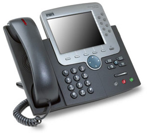
Good afternoon, dear harazhiteli. In this article, I will try to consider the basic principles of IP-telephony, describe the most commonly used protocols, indicate methods for encoding and decoding voices, and analyze some common problems.
Under IP-telephony is meant voice communication, which is carried out over data transmission networks, in particular over IP-networks (IP - Internet Protocol). Today, IP-telephony is increasingly replacing traditional telephone networks due to ease of deployment, low call costs, ease of configuration, high quality communications and comparative security of the connection. In this presentation, we will adhere to the principles of the OSI reference model (Open Systems Interconnection basic reference model) and talk about the subject “bottom-up”, starting with the physical and channel levels and ending with data levels.
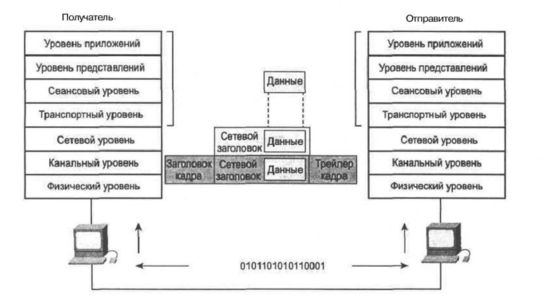 "
" OSI Model and Data Encapsulation
Principles of IP Telephony
When making a call, the voice signal is converted into a compressed data packet (this process will be discussed in more detail in the chapters “Pulse code modulation” and “Codecs”). Next, packet data is sent over packet-switched networks, in particular IP networks. When packets reach the recipient, they are decoded into the original voice signals. These processes are possible due to the large number of auxiliary protocols, some of which will be discussed later.
In this context, the data transfer protocol is a certain language that allows two subscribers to understand each other and ensure high-quality data transfer between two points.
Unlike traditional telephony
In traditional telephony, the connection is established using the telephone exchange and is intended solely for the purpose of conversation. Here, voice signals are transmitted over telephone lines, through a dedicated connection. In the case of IP-telephony, the compressed data packets arrive in the global or local area network with a specific address and are transmitted based on this address. In this case, IP addressing is already used, with all its inherent features (such as routing).
At the same time, IP-telephony is a cheaper solution for both the operator and the subscriber. This is due to the fact that:
- Traditional telephone networks have excessive performance, while IP-telephony uses voice packet compression technology and allows you to fully utilize the capacity of the telephone line.
- As a rule, at the moment everyone has access to the global network, which allows to reduce connection costs or completely eliminate them.
- Calls on the local network can use the internal server and occur without the participation of an external exchange.
Together with the above, IP-telephony can improve the quality of communication. This is achieved, again, thanks to three main factors:
- Telephone servers are constantly being improved and their work algorithms are becoming more resistant to delays or other problems of IP networks.
- In private networks, their owners have full control over the situation and can change parameters such as bandwidth, number of subscribers on one line, and, as a result, the amount of delay.
- Packet-switched networks are evolving, and new protocols and technologies are introduced annually to improve communication quality (for example, the RSVP bandwidth reservation protocol).
Thanks to IP-telephony, the busy line problem is very elegantly solved, since call forwarding or transfer to standby mode can be carried out by several commands in the configuration file on the PBX.
Physical Layer
At the physical level, a bit stream is transmitted over the physical medium through the corresponding interface. IP telephony relies almost entirely on existing network infrastructure. As an information transfer medium, as a rule, twisted pair Category 5 (UTP5), single-mode or multi-mode optical fiber, or coaxial cable are used. Thus, the principle of convergence of telecommunication networks is fully implemented.
PoE
It is interesting to consider PoE (Power Over Ethernet) technology - IEEE 802.3 af-2003 and IEEE 802.3at-2009 standards. Its essence lies in the ability to provide power to devices through a standard twisted pair cable. Most modern IP phones, in particular the Cisco Unified IP Phones 7900 Series, come with PoE support. According to the 2009 standard, devices can receive current up to 25.5 watts.
When power is supplied, only two twisted pairs of 100BASE-TX cable are used, however, some manufacturers use all four, reaching power up to 51 watts. It should be noted that the technology does not require modification of existing cable systems, including Cat 5 cables.
To determine whether the connected device is a powered device (PD - powered device), a voltage of 2.8-10 V is applied to the cable. Thus, the resistance of the connected device is calculated. If this resistance is in the range of 19 - 26.5 kOhm, then the process proceeds to the next stage. If not, the test is repeated with an interval of ≥2 ms.
Next, the power range of the powered device is searched by applying a higher voltage and measuring the current in the line. Following this, 48 V is supplied to the line - the supply voltage. Constant control of overloads is also carried out.
Link layer (Data Link Layer)
According to the IEEE 802 specification, the link layer is divided into two sublevels:
- MAC (Media Access Control) - provides interaction with the physical layer;
- LLC (Logical Link Control) - serves the network layer.
At the data link layer, switches work - devices that provide the connection of several nodes of a computer network and the distribution of frames between hosts based on physical (MAC) addressing.
It is necessary to mention the mechanism of virtual local area networks (Virtual Local Area Network). This technology allows you to create a logical network topology without regard to its physical properties. This is achieved by tagging traffic, which is described in detail in the IEEE 802.1Q standard.
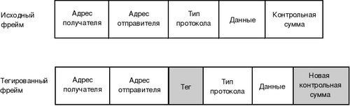
Frame format
In the context of IP telephony, we note the Voice VLAN, which is widely used to isolate voice traffic generated by IP phones from other data. Its use is advisable for two reasons:
- Security. Creating a separate voice VLAN reduces the likelihood of intercepting and analyzing voice packets.
- Improving transmission quality. The VLAN mechanism allows you to set an increased priority for voice packets, and, as a result, improve the quality of communication.
Network Layer
At the network level, routing occurs, respectively, the main devices of the network level are routers. It is here that determines how the data reaches the recipient with a specific IP address.
The main routable protocol is IP (Internet Protocol), on the basis of which IP-telephony is built, as well as the world wide Internet. There are also many dynamic routing protocols, the most popular of which is OSPF (Open Shortest Path First) - an internal protocol based on the current state of communication channels;
To date, there are special VoIP-gateways (Voice Over IP Gateway) that provide the connection of conventional analog phones to the IP-network. As a rule, they also have a built-in router that allows you to keep track of traffic, authorize users, automatically distribute IP addresses, and manage bandwidth.
Among the standard features of VoIP gateways:
- Security functions (creation of access lists, authorization);
- Fax support
- Voice mail support;
- Support for H.323, SIP (Session Initiation Protocol).
To deal with possible delays in the transmission of IP, it is necessary to supplement it with additional means, for example, priority-setting protocols (so that voice data does not compete with normal).
As a rule, for these purposes, routers use low-latency queuing (LLQ) or class-based weighted queuing (CBWFQ - Class-Based Weighted Fair Queuing).
In addition, labeling schemes with prioritization are needed to consider voice data as the most important for transmission.
Transport Layer
The transport level is characterized by:
- Data segmentation of top-level applications;
- Providing end-to-end connection;
- Guaranteed data reliability.
The main transport layer protocols are TCP (Transmission Control Protocol), UDP (User Datagram Protocol), RTP (Real-time Transport Protocol). Directly in IP-telephony, UDP and RTP protocols are used, and their main difference from TCP is that they do not provide reliable data delivery. This is a more acceptable option than delivery control (TCP), since telephony is extremely dependent on transmission delays, but less sensitive to packet loss.
UDP
UDP is based on the IP network protocol and provides transport services to application processes. Its main difference from TCP is the provision of non-guaranteed delivery, that is, when sending and receiving data, no confirmations are requested. Also, when sending information, it is not necessary to establish a logical connection between UDP modules (source and receiver).
RTP
Despite the fact that RTP is considered to be a transport layer protocol, as a rule it works on top of UDP. Using RTP, traffic type recognition, time-stamping, transmission control, and packet sequence numbering are implemented.
The main purpose of RTP is that it assigns timestamps to each outgoing packet that are processed on the receiving side. This allows you to receive data in the proper order, reduces the impact of uneven packet transit times over the network, and restores synchronization between audio and video data.
Data Layers
The last three levels of the OSI model will be considered together. Such a union is permissible, since the processes occurring at these levels are closely interconnected, and it would be more logical to describe them regardless of the division into sublevels.
H.323
The first step is to describe the H.323 protocol stack developed in 1996. This standard describes equipment, network services and terminal devices for audio and video communications in packet-switched networks (Internet). For any H.323 standard device, voice sharing is required.
H.323 recommends:
- Platform independence.
- Coding standards for analog data.
- Bandwidth management.
- Flexibility and compatibility.
Note a very important fact: the recommendations do not define the physical transmission medium, transport protocol and network interface. This means that devices that support the H.323 standard can work on any packet-switched network that exists today.
According to H.323, the four main components of a VoIP connection are:
- terminal;
- Gateway;
- zone controller
- Multipoint Conference Unit (MCU).
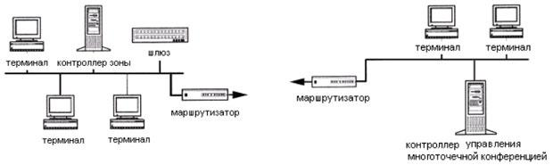
An example of a network block diagram in IP telephony
Excerpt from H.323 Protocol Stack Document
1. Connection control and alarm:
1.a. H.225.0: multimedia stream signaling and packetization protocols (uses a subset of the Q.931 signaling protocol).
1.b. H.225.0 / RAS: Registration, Admission and Status Procedures.
1.c. H.245: control protocol for multimedia.
2. Sound signal processing:
2.a. G.711: pulse code modulation of tonal frequencies.
2.b. G.722: 7 kHz audio coding at 64 kbps.
2.c. G.723.1: speech encoders at two transmission rates for multimedia communication with a transmission rate of 5.3 and 6.3 kbit / s.
2.d. G.728: 16 kbit / s speech coding using linear prediction with low latency excitation coding.
2.d. G.729: coding of 8 kbit / s speech signals using linear prediction with algebraic coding of an excitation signal of a conjugate structure.
3. Processing of video signals:
3.a. H.261: Video codecs for audiovisual services at 64 kbps.
3.b. H.263: encoding a video signal for low speed transmission.
4. Conference call for data transfer:
4.a. T.120: protocol stack (includes T.123, T.124, T.125) for transferring data between endpoints.
5. Multimedia transmission:
5.a. RTP: real-time transport protocol.
5 B. RTCP: Real-time Transmission Control Protocol.
6. Security:
6.a. H.235: Security and encryption for multimedia terminals on an H.323 network.
7. Additional services:
7.a. H.450.1: Generalized functions for managing supplementary services in H.323.
7.b. H.450.2: transfer the connection to the telephone number of the third party.
7.c. H.450.3: call forwarding.
7.d. H.450.4: call hold.
7.d H.450.5: call park (park) and call pickup.
7..e. H.450.6: Notification of an incoming call in a conversation state.
7.g. H.450.7: indication of a waiting message.
7.h. H.450.8: name identification service.
7.i. H.450.9: connection termination service for H.323 networks.
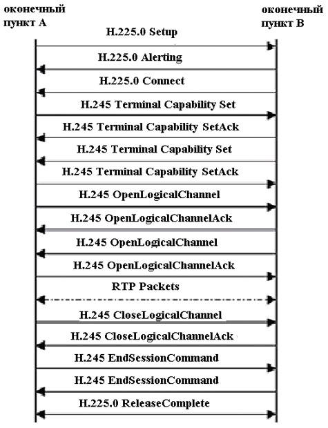
H.323-based connection setup script
SIP (Session Initiation Protocol)
SIP is a signaling protocol designed to organize, modify, and terminate communication sessions. SIP is independent of transport technology, however, it is preferable to use UDP when establishing a connection. It is recommended to use RTP to transmit the voice and video information itself, but the possibility of using other protocols is not excluded.
SIP defines two types of signaling messages - request and response. There are also six procedures:
- INVITE (invitation) - invites the user to participate in a communication session (serves to establish a new connection; may contain parameters for approval);
- BYE (disconnect) - terminates the connection between two users;
- OPTIONS (options) - used to transfer information about the supported characteristics (this transfer can be carried out directly between two user agents or through a SIP server);
- ASK (confirmation) - used to confirm receipt of a message or to respond positively to an INVITE command;
- CANCEL (cancel) - stops user search;
- REGISTER (registration) - transmits information about the user's location to the SIP server, which can broadcast it to the address server (Location Server).
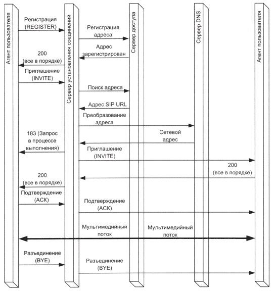
SIP Session Script
Codecs
An audio codec is a program or algorithm that compresses or decompresses digital audio data, thereby reducing the bandwidth requirements of the data channel. In IP-telephony, conversion by means of the G.729 codec, as well as G.711 compression according to the A-law (alaw) and μ-law (ulaw) are the most common today.
G.729
G.729 is a codec that compresses the original signal with data loss. The main idea laid down in G.729 is the transmission not of the digitized signal itself, but of its parameters (spectral characteristics, the number of transitions through zero), sufficient for subsequent synthesis on the receiving side. At the same time, all the basic characteristics of the voice, such as amplitude and timbre, are preserved.
The channel capacity for which this codec is designed is 8 kbps. The frame length of the processed G.729 is 10 ms, the sampling frequency is 8 kHz. For each of these frames, the parameters of the mathematical model are determined, which are subsequently transmitted to the channel in the form of codes.
When using G.729 encoding, the delay is 15 ms, of which 5 ms is spent filling the preliminary buffer. We also note that the G.729 codec places rather high demands on processor resources.
G.711
G.711 is a voice codec that does not involve any compression other than companding, a method of reducing the effects of channels with a limited dynamic range. The basis of this method is the principle of reducing the number of quantization levels of a signal in the high volume region, while maintaining sound quality. Two widely used companding schemes in telephony are alaw and ulaw.
The signal in this codec is provided by a stream of 64 kbit / s. Sampling rate - 8000 frames at 8 bits per second. Voice quality is subjectively better than using the G.729 codec.
alaw
alaw or A-law - an algorithm for compressing audio data with loss of information. It is mainly used in Europe and Russia.
For signal x, the alaw transform is as follows:

Where A is the compression parameter (usually assumed to be 87.7).
ulaw
ulaw or μ-law is an audio data compression algorithm with loss of information. It is mainly used in Japan and North America.
For signal x, the ulaw transform is as follows:

where μ is taken equal to 255 (8 bits) in the standards of North America and Japan.
Pulse Code Modulation (PCM - Pulse Code Modulation)
Pulse code modulation - the transfer of a continuous function in the form of a series of consecutive pulses.
To obtain a modulated signal at the input of the communication channel, the instantaneous value of the carrier signal is measured by the ADC with a certain period. In this case, the number of digitized values per second (otherwise, the sampling frequency) must be greater than or equal to twice the maximum frequency in the spectrum of the analog signal.
Further, the obtained values are rounded to one of the previously accepted levels. Note that the number of levels must be taken as a multiple of the power of two. Depending on how many levels were determined, the signal is encoded with a certain number of bits.
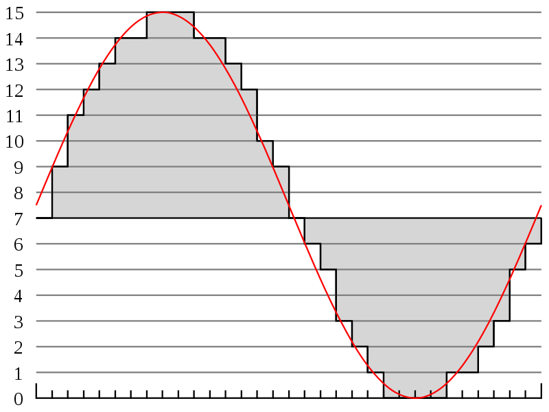
Signal quantization
This figure shows the coding using four bits (that is, all intermediate values of the analog signal will be rounded to one of the predefined 16 levels). For example, at a time equal to zero, the signal will be presented in a similar way: 0111.
When demodulating, a sequence of zeros and ones is converted into pulses by a demodulator, the quantization level of which is equal to the quantization level of the modulator. After that, the DAC, based on these pulses, restores the signal, and the smoothing filter finally eliminates inaccuracies.
In modern telephony, the number of quantization levels must be greater than or equal to 100, that is, the minimum number of bits by which a signal can be encoded is 7.
Quality of Service - QoS Issues
In networks based on the TCP / IP stack, high-quality traffic service that is sensitive to transmission delays is not provided by default. When using the TCP protocol, there is a guarantee of reliable information delivery, but its transfer can be carried out with unpredictable delays. UDP is characterized by minimization of delays, but there is no guarantee of correct packet delivery.
At the same time, the quality factor of voice traffic strongly depends on the quality of transmission, and in a network where mechanisms are not implemented that guarantee appropriate quality, the implementation of IP-telephony may not meet the requirements of users.
The main indicators of quality of service are network bandwidth and transmission delay. The delay in this case is defined as the period of time elapsed from the moment a packet was sent until it was received.
There are also such characteristics as network availability and reliability (evaluated by the results of monitoring the level of service for a long time, or by the utilization rate).
The following mechanisms are used to improve communication quality:
- Rerouting. When one of the communication channels is overloaded, it allows delivery via backup routes.
- Reservation of communication channel resources for the duration of the connection.
- Prioritization of traffic. It enables you to mark packages according to their importance level and perform service based on labels.
As mentioned earlier, voice traffic is extremely sensitive to transmission delays. The maximum delay time should not exceed 400 ms (this also includes the duration of information processing at the end stations). There are two main types of delays:
- Delay when encoding information in voice gateways or terminal equipment. It is reduced by improving voice processing and conversion algorithms.
- Delay introduced by the transmission network. It is reduced by improving network infrastructure, in particular, reducing the number of routers and using high-speed channels.
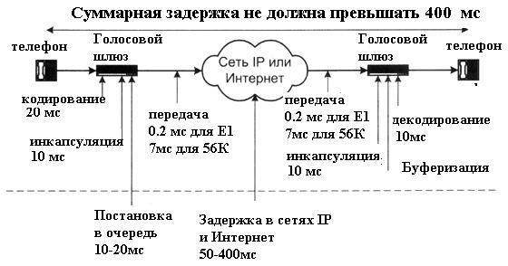
Sources of Delays in IP Telephony
Jitter
Another phenomenon characteristic of IP-telephony is jitter, or, in other words, a random delay in the distribution of a packet.
Jitter is caused by three factors:
- Limited bandwidth or incorrect operation of active network devices;
- High signal propagation delay;
- Thermal noise.
The most commonly used method of dealing with jitter is the jitter buffer, which stores a certain number of packets.
Usually, dynamic adjustment of the buffer length over the entire lifetime of the connection is provided. Heuristic algorithms are used to select the best length.
Jitter buffer
To compensate for the uneven packet arrival rate, a temporary packet storage, or so-called jitter buffer, is created at the receiving side. Its task is to collect the incoming packets in the correct order in accordance with the time stamps and issue them to the codec at the correct intervals and in the correct order.

Jitter buffer The
size of the buffer the receiving VOIP device calculates during operation, or is forcibly set in the settings. On the one hand, it cannot be too large so as not to increase the transport delay. On the other hand, a small buffer size causes packet loss due to delay times in the IP network.
From here comes one of the main contradictions between Internet providers and IP telephony users. From the point of view of the provider, all packets are delivered to the subscriber, that is, there are no losses. And from the point of view of the VoIP device, the time difference between the arrival of packets significantly exceeds the jitter buffer. Therefore, in fact, there are losses. In practice, a loss of more than 1% causes certain unpleasant sensations. At 2%, the conversation is difficult. With values greater than 4%, conversation is almost impossible.
Jitter buffer size
The random propagation delay Ji for the i-th packet can be determined by the formula:

where:
Di is the deviation from the expected arrival time of the i-th packet.
The deviation from the expected arrival time of the i-th packet Di is determined by the formula:

where:
R is the packet arrival time in RTP timestamps,
S is the RTP timestamp taken from the packet.
Here is an example of calculating the expected size of the random propagation delay of the 5th packet, based on the previous two.
Let J4 = 10 ms; R4 = 10, R3 = 11, S4 = 6, S3 = 5, then D5 will be equal to (10-11) - (6-5) = - 2.

On average, the random delay of the propagation time for one packet in the current example will be 10 ms (more precisely, it can be calculated according to the formula above). Then, so that no packet is discarded, the size of the jitter buffer should be 10 ms.
To determine the required size of the jitter buffer in megabytes, we multiply the resulting value by 100 Mbps - the average network bandwidth: 10 • 10 ^ -3 • 100 = 128 kb.
The size of the jitter buffer should be larger than the fluctuation of the transit time in the network. For example, if for 10 packets the transit time varies from 5 to 10 ms, then the buffer must be at least 8 ms so that no packet is lost. It is better if the buffer is even larger, for example 12 ms, then the mechanism for re-requesting lost packets can work.
Telephone Network Deployment Solutions
Asterisk

Asterisk is a software-based PBX capable of switching both VoIP calls and calls made between IP phones and a traditional public switched telephone network.
Supported protocols: IAX, SIP, H.323, Skinny, UNIStim.
Supported codecs: G.711 (ulaw and alaw), G.722, G.723, G.729, GSM, iLBC, LPC-10, Speex.
Asterisk is a dynamic open source software that can be installed without regard to licensing. This makes this software PBX attractive for small and medium-sized businesses. The number of subscribers in the network can reach 2000 and is limited only by server capacity.
Another advantage of Asterisk is the ability to flexibly configure. All necessary functionality is either already implemented, or can be added independently without significant time and money costs. The principle contributes to this: one task - one software module.
Compared to solutions from vendors such as Cisco or Avaya, Asterisk also has an attractive deployment cost. In fact, all the costs come down only to the purchase of telephones and a server that can provide the required network load. The program itself is absolutely free.
Cisco Unified Communication Manager (CallManager)
CallManager is more likely for large networks with up to 30,000 subscribers. This software and hardware complex provides reliable operation and allows you to configure many parameters, such as call forwarding or voice menu. There is also a “lite" express version, intended more for small offices.
Of the benefits of Cisco CallManager, it is worth noting, first of all, the famous technical support from Cisco. With an appropriate level of a service contract, any problem, from setup questions to equipment that is out of order, will be solved almost instantly. Therefore, Cisco CallManager is suitable for companies willing to pay a lot of money, but also receive the highest quality of service.
Avaya IP Office

IP Office can be a good choice for a medium sized telephone network. The number of subscribers here is limited not only by the server capacity, but also by the number of licenses purchased. Almost everything needs to be licensed - expansion cards, used applications, etc., which can cause certain inconveniences.
Configuration can be done through a number of programs, but the most popular and easiest to use is Avaya IP Office Manager. It is also possible to control through the console using Avaya Terminal Emulator.
In general, Avaya products are not limited to one IP Office. Avaya, merged with another well-known manufacturer Nortel in 2009, is a recognized leader in the IP telephony equipment market.
What can be read on the topic:
- Wendell Odom - all his books are good.
- “IP Telephony in Computer Networks.” I.V. Baskakov, A.V. Proletarsky, S.A. Melnikov, R.A. Fedotov.
- “IP telephony”. B.S. Goldstein, A.V. Pinchuk, A.L. Sukhovitsky.
- “Asterisk. The future of telephony. ” Jim Van Meggelen, Leif Madsen, Jared Smith.
- “SIP protocol. Directory". B.S. Goldstein, A.A. Zarubin, V.V. Samorezov.