Improving 3D printing quality with cooling
 So, you have already come a long way and assembled your own 3d printer. It's time to fight for print quality. In this article we’ll talk about why you need to cool the model when printing, what you need to pay attention to when developing a cooling system, and how to properly connect a fan using the SevenSwitch chip and Teacup firmware .
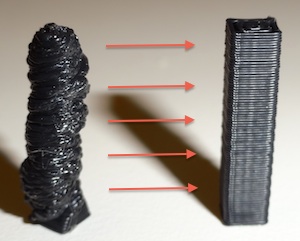
When printing, the plastic is heated to its melting point and squeezed out through the nozzle of the print head. In this case, the head literally smoothes the top layer according to the model. If the size of this layer is small compared to the size of the head itself, then the head is constantly above the printed surface. This leads to the fact that the already laid plastic begins to melt and spoil the model. To solve this problem, cooling is used.
 The easiest way to organize cooling is software. It does not require absolutely any changes in the printer. The idea is to lay the print head to the side while printing small-sized layers for a while to allow the model to cool. Skeinforge has settingsallowing to achieve this behavior. In other slicers (for example, Slic3r) there are no such settings yet, so you can simply add a small additional object for printing, which the printer will have to move its head to a sufficient distance.
Unfortunately, software cooling is often not enough, so most advanced 3d printers have a special fan that cools the printed model. To improve print quality without modifying the printer, you can put a desktop fan and direct it towards the printed model. The disadvantage of this option is the need to turn the fan on and off with your hands and the inability to precisely control the strength and direction of blowing. A more complex and perfect option is to connect the fan to the electronics to control the blowing force and make an air duct to form the desired flow direction. Let's talk about it in more detail.
There are several pitfalls to be aware of when choosing or designing an air duct yourself:
- Firstly, if the fan blows directly to the heater of the print head, this can lead to the fact that the heater will no longer cope with the heating of the plastic and at the most crucial moment the temperature may not be high enough for printing. Therefore, when choosing a finished one or making your own duct, try to avoid strong direct blowing of the heater and nozzle. Warming the heater with fiberglass or silicone foam and kapton tape can help solve this problem.
- Secondly, if the fan blows strongly on the heated table of the 3d printer, this can lead to the model sticking poorly and / or breaking off during printing. To solve this problem, turn off the cooling when printing the first few layers of the model, and also choose the fan wisely. More in this case does not mean better. If the model has a small base, its adhesion can be improved by generating edges (skirt module in skeinforge and brim parameter in slic3r).
- Thirdly, aerodynamics is a complicated thing. Sometimes visually ideal and logical duct models do not work in practice. Therefore, before installing on the printer, test that the air flow is as planned. Ideally, it should blow well the plastic exiting the nozzle, but not touch the nozzle itself.

You can install the fan directly on the print carriage or on the printer frame and supply air to the carriage through a flexible hose. Both implementations work equally well, but the second allows you to use a larger fan and make the carriage easier, which reduces the amount of vibration.
I have a Greg carriage with mounts for two fans . I did not manage to find a suitable duct model on thingiverse and decided to make it myself . To start, I made simple ducts that redirect the flow down. This design does not claim to be ideal, it just allowed me not to invent a fan mount on my carriage. I think this and such an option should work well .
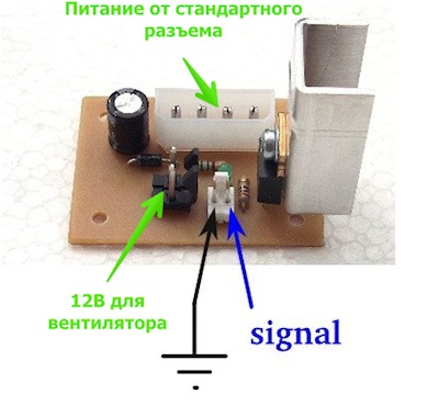
Now let's talk about connecting a fan. Your electronics may already have fan control. Then you can simply insert the connector into the desired location. If not, you will need to use the SevenSwitch chip, the manufacturing process of which and the list of necessary parts are described in detail in the RepRap Wiki . If you do not know how to make printed circuit boards, then you can simply solder everything with a hinged installation. The principle of connecting the board is extremely simple. The 12V power is taken from the standard connector of the computer power supply, the input receives mass and a logical signal from the microcontroller, the wires go to the fan to the output. If the microcontroller leg supports PWM (for the uninitiated, what is the PWM can be read here), then you can control the fan speed. This may be helpful. On my printer, I keep the fan constantly on at low speed starting from the second layer, increasing the speed of blowing when printing small layers.
 Next, we will talk about connecting SevenSwitch to Gen7 electronics with an ATMEGA1264P-PU microcontroller based on Teacup firmware. Therefore, you can not read if you have a different combination of firmware and electronics.
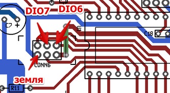
 On Gen7 electronics, it is convenient to use the ISP connector, which is marked CONN6 on the circuit board. It's simple: mass to mass, the control leg to the output of the DIO6 or DIO7. When using the ATMEGA1264P microcontroller, PWM can be used on both of these legs. I chose DIO7.
Configure the firmware. To do this, we write one more “heater” in config.h. You need to add a line in bold:
// name port pwm
DEFINE_HEATER (extruder, DIO4, 1)
DEFINE_HEATER (bed, DIO3, 1)
DEFINE_HEATER (to fan, DIO7, 1)
#define HEATER_EXTRUDER HEATER_extruder
#define HEATER_BED HEATER_bed
#define HEATER_FAN HEATER_fan
Teacup uses a common h file, for ATMEGA644P and ATMEGA1264P. The 644th mega on the legs DIO6 and DIO7 does not have PWM, but 1264 has it. Therefore, we prescribe the addresses of the PWM registers for ATMEGA1264P. In the arduino_644.h file, change:
#define DIO6_PWM NULL
#define DIO7_PWM NULL
to:
#define DIO6_PWM & OCR3AL
#define DIO7_PWM& OCR3BL
To test the operation of the fan, connect to the printer using Pronterface or another program that allows you to manually send commands to the printer and sequentially send:
M106 S255 // turn on the fan at full power
M106 S128 // reduce the speed
M106 S0 // turn off the fan
If you reverse polarity when you connect the fan, it will not spin. Therefore, if the fan does not work, try changing the power wires in some places.
It should be noted that about connecting a fan to Gen7 there is already an excellent article with pictures in French , but it does not say about changes in the firmware for PWM, so I duplicated part of the description here.
Well, the hardest part left to turn on the fan control in your favorite model slicer and you're done. For a detailed description of how to do this, I will send you to the documentation for your slicer.