 April 20, 2013 at 23:47
DIY laser show. Part 2
Now that you have read (or not read) all this boring theory from the first part , we will take up practical experiments. If you have an analog oscilloscope lying around in your household, then you can make almost no effort to output a video to it.
You can see the structural diagram of a simple laser projector below:

It is quite primitive and does not contain a thermal stabilization system for lasers, a safety shutter and other joys of a real projector builder.
This system works as follows: Files with vector images / video in a special format are downloaded to a computer or to a graphic controller. The control program converts these files into a stream of points, each of which is characterized by the deflection angle of the galvanometer mirrors vertically and horizontally, as well as the laser radiation power. The DAC generates analog signals from this stream to control the ILDA laser projector. All DAC outputs are differential couples with a ± 10V span for galvanometer control and ± 5V for laser drivers. The galvanometer control circuit, having received new values of the angle of rotation from the DAC, instantly changes the position of the mirrors and stabilizes them in a new place (the galvanometers have feedback on the position of the mirror and a smart PID controller). Drivers provide the output of the laser diodes with a beam intensity proportional to the input voltage. The laser beams mixing on a special mirror system fall on the mirrors of galvanometers, and at the exit we have a drawing (scanning) laser beam of the color and brightness that only suits us.
To build and admire this miraculous aggregate, you will need:
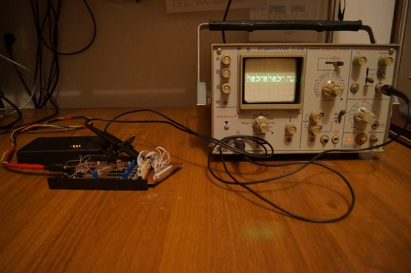
You should get something like this:
The picture is slightly distorted due to the presence of isolation capacitors at the output of the DAC of the sound card, which do not pass the constant component. If you remove them and add the simplest amplifier to the op amp (a slightly modified output stage from the circuit below), you will get a full-fledged DAC for laser graphics. Its only drawback is the small sampling frequencies, which will not allow you to draw complex multi-element pictures or raster.
A more serious DAC devoid of these shortcomings can be assembled according to the schemes below.
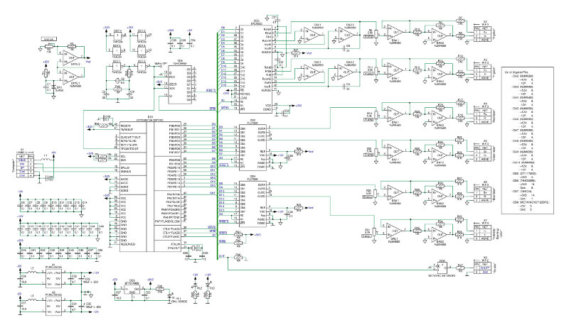
DAC board:
Zoom
Adapter on a standard connector ILDA:

Enlarge
microcontroller DD1 CY7C68013A communicates via USB 2.0 and contains a FIFO buffer for the USB endpointov. The GPIF logic machine integrated in the controller is configured so that without using the controller itself, it instantly download data from the endpoint buffer to the corresponding DACs using the clock signal. It turned out something like a high-speed sound card, with sampling up to several megahertz. All DACs and a voltage reference were ordered from Texas Instruments as samples.
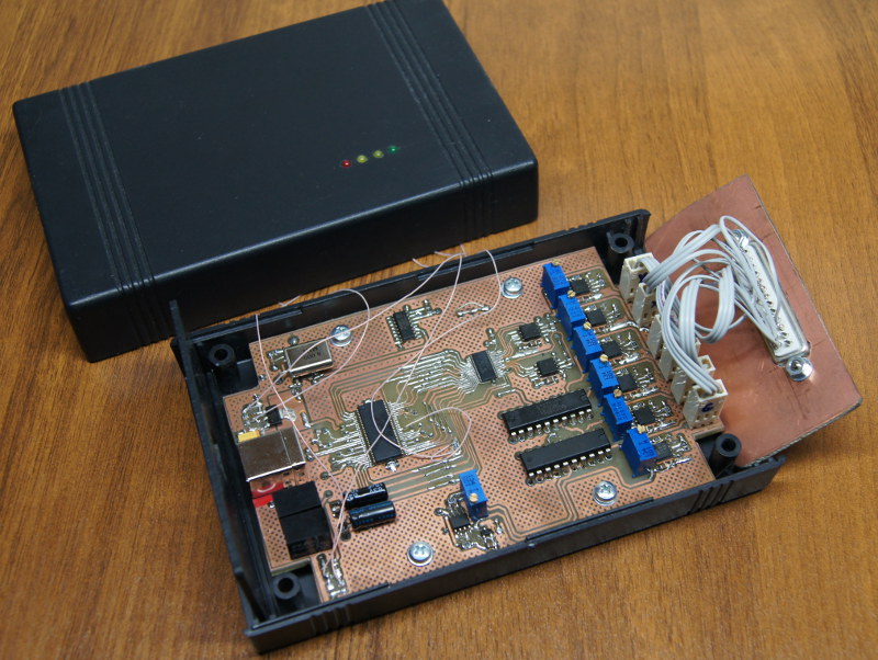
This is how it looks when assembled:
The firmware will be, but a little later.
In the next series, I will tell you how to assemble an analog-controlled laser driver.
You can see the structural diagram of a simple laser projector below:
It is quite primitive and does not contain a thermal stabilization system for lasers, a safety shutter and other joys of a real projector builder.
This system works as follows: Files with vector images / video in a special format are downloaded to a computer or to a graphic controller. The control program converts these files into a stream of points, each of which is characterized by the deflection angle of the galvanometer mirrors vertically and horizontally, as well as the laser radiation power. The DAC generates analog signals from this stream to control the ILDA laser projector. All DAC outputs are differential couples with a ± 10V span for galvanometer control and ± 5V for laser drivers. The galvanometer control circuit, having received new values of the angle of rotation from the DAC, instantly changes the position of the mirrors and stabilizes them in a new place (the galvanometers have feedback on the position of the mirror and a smart PID controller). Drivers provide the output of the laser diodes with a beam intensity proportional to the input voltage. The laser beams mixing on a special mirror system fall on the mirrors of galvanometers, and at the exit we have a drawing (scanning) laser beam of the color and brightness that only suits us.
The simplest DAC for a laser projector
To build and admire this miraculous aggregate, you will need:
- Windows computer with sound card;
- A piece of wire with a Jack 3.5 connector from Chinese headphones;
- Analog oscilloscope with the ability to work in X / Y scan mode;
- Download sourceforge.net: LFI Player 3D Laser Display Software ;
- Laser Video File: Dolphin Animation A Slice of Bad Apple .
- Unzip LFI Player, and edit the EzAudDac.ini file in its directory for your system:
UseCardNumber parameter, select the number of the sound card with which we will work.; Пример моей конфигурации, для компьютера с одной звуковой картой [Sound Card Selection] UseCardNumber=1 LowLatencyBuffering=no SampleRate=48000 RepeatFrameWhenOut=no [Channel Invert] X=no Y=no R=yes G=yes B=yes I=yes [Channel Selection] X=1 Y=2 R=0 G=0 B=0 I=0 AL=0 AR=0 - Connect the oscilloscope probes to the outputs of the left and right channels of the sound card using the audio connector with a wire, switch the oscilloscope to X / Y scan mode
- Run LFI_Player_V1_1_6_EzAudDAC.exe, open the ILD file in it, and click Play. On the oscilloscope, you can watch vector animation.
You should get something like this:
The picture is slightly distorted due to the presence of isolation capacitors at the output of the DAC of the sound card, which do not pass the constant component. If you remove them and add the simplest amplifier to the op amp (a slightly modified output stage from the circuit below), you will get a full-fledged DAC for laser graphics. Its only drawback is the small sampling frequencies, which will not allow you to draw complex multi-element pictures or raster.
High speed DAC
A more serious DAC devoid of these shortcomings can be assembled according to the schemes below.
DAC board:
Zoom
Adapter on a standard connector ILDA:
Enlarge
microcontroller DD1 CY7C68013A communicates via USB 2.0 and contains a FIFO buffer for the USB endpointov. The GPIF logic machine integrated in the controller is configured so that without using the controller itself, it instantly download data from the endpoint buffer to the corresponding DACs using the clock signal. It turned out something like a high-speed sound card, with sampling up to several megahertz. All DACs and a voltage reference were ordered from Texas Instruments as samples.
This is how it looks when assembled:
The firmware will be, but a little later.
In the next series, I will tell you how to assemble an analog-controlled laser driver.











