APSX-1250 Inverter Overview
The APSX 1250 inverter fell into the hands. Full name: PowerVerter APSX 1250. The
converter is the PowerVerter APS X series charger for an output load of 1250 Watts with automatic switching of power modes: Main-Stand-alone.
Where it can be applied:
System of reserve power supply of small power.
This is not a uninterruptible power supply in the classical sense of the term - UPS.
This is an option for long battery life, up to several tens of hours of load, instead of using a portable power station.
The system is quite autonomous and does not require user intervention to change operating modes. Everything happens automatically. There is a network, the load works from the network.
If the external voltage 220 V disappears, the inverter automatically switches to battery mode.
In mains operation, the inverter operates as a charger, providing a charge for the connected batteries.
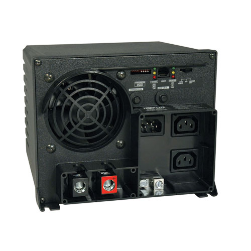
Appearance APSX-1250
Input
12 Volt DC voltage, battery.
230 V for supplying to the load
Output
230 V, 50 Hz; 2 output sockets. To connect the load. Two sockets type C13. Included is an adapter from the C13 connector to a standard plug connection - allows you to use an extension cord to connect consumers.
Mode switching time: Basic-Standalone for about half the period. In other words, switching is fast enough, but it may turn out to be “visible” to sensitive consumers.
The maximum output power of the converter: 1250 W constant load.
Recommended maximum load power up to 700-1000 watts.
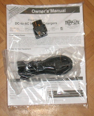
APSX-1250 Included cable and adapter
Battery Charge A
three - stage charger for bulk and sealed batteries provides a charge current of 7.5 / 30 A.
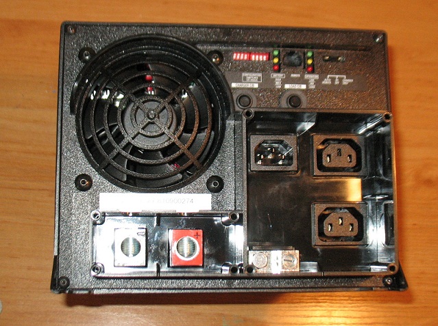
The photo shows the bottom or back of the inverter. The photo shows the terminals for connecting batteries. Connectors for network and load.
Protective thermal breakers for battery and connected load operation.
A battery fuse is not supplied.
Typical user errors when connecting the APSX 1250 inverter
Almost all users do not install a fuse in the battery circuit. This is one of the main inverter connection errors.
In addition, I had to observe many cases of non-compliance with the cable cross-section for connecting batteries.
Recommendations for connecting the APSX 1250 inverter The
maximum working current in the battery circuit when switching to battery mode can reach 119 amperes.
Obviously, you must install a fuse in the battery circuit. This is stated in the instruction manual.
In the same photo: Sample cable for connecting the battery. Everything that looks different will work, maybe it will, but it is likely that it will not last long.
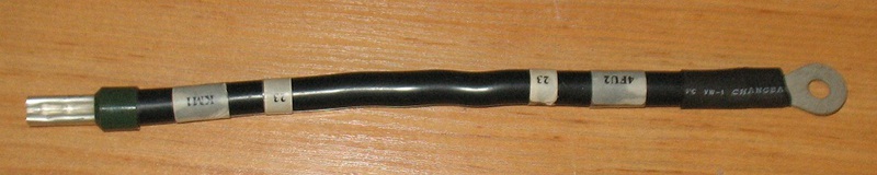
Cable Connection Sample
Reliability of any other type of connection
Bare conductors, without termination with a sleeve and a tip for connecting to the battery.
Soldered wire, without sleeve.
All this is a big question. In other words, there are no guarantees of reliable operation for many years.
Why? The answer to this question is very simple. During operation, the current in the battery circuit can reach large values. Keep this in mind by using the appropriate cross-section of the cable connections of the battery circuit.
At the same time, a reliable contact on the terminals of the battery terminals and in the cable connection terminal is required. The operation of the logic and control and management of the inverter is provided by an internal unit that operates on battery voltage. The slightest violation of the battery circuit, loss of contact for a split second and the inverter will turn off, while the load is de-energized. The system will become completely inoperative.
In addition, most cases of failure of batteries and inverters are not a proper connection.
When using open, non-sealed or automotive batteries, the inverter must be isolated from the batteries and never install the inverter in close proximity to such batteries.
Configuration and setup
Depending on the type of batteries used, their number, it is necessary to configure the inverter.
Two groups of switches next to the LEDs displaying the operating mode and battery level are responsible for this.
All switching and settings must be done before connecting the network and batteries, and only then make the connection.
Very important note: In most cases, the factory settings, the position of the switches does not correspond to the real system that you install and plan to operate.
Incorrect configuration of the switches - and possible battery failure, not reliable operation of the inverter.
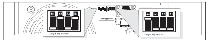
APSX1250 inverter, switch configuration
Recommendations when using as a backup power supply of heating systems, automatic control of boilers of heating systems
One of the applications of these inverters is backup power supply of circulation pumps and automation of heating systems.
In this application, grounding and neutral monitoring are important. Otherwise, the automation of the heating systems does not work.
When connecting the inverter, it is necessary to take into account the control of these circuits and ensure the presence of neutral when connecting the inverter.
In most cases, automatic control of boilers does not work if the connection scheme of not only inverters is not correct, but when connecting portable backup power plants.
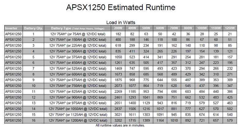
Estimated Battery Life Table for APSX 1250 Inverter
MUK-Service - all types of IT repair: warranty, non-warranty repair, sale of spare parts, contract service
converter is the PowerVerter APS X series charger for an output load of 1250 Watts with automatic switching of power modes: Main-Stand-alone.
Where it can be applied:
System of reserve power supply of small power.
This is not a uninterruptible power supply in the classical sense of the term - UPS.
This is an option for long battery life, up to several tens of hours of load, instead of using a portable power station.
The system is quite autonomous and does not require user intervention to change operating modes. Everything happens automatically. There is a network, the load works from the network.
If the external voltage 220 V disappears, the inverter automatically switches to battery mode.
In mains operation, the inverter operates as a charger, providing a charge for the connected batteries.
Appearance APSX-1250
Input
12 Volt DC voltage, battery.
230 V for supplying to the load
Output
230 V, 50 Hz; 2 output sockets. To connect the load. Two sockets type C13. Included is an adapter from the C13 connector to a standard plug connection - allows you to use an extension cord to connect consumers.
Mode switching time: Basic-Standalone for about half the period. In other words, switching is fast enough, but it may turn out to be “visible” to sensitive consumers.
The maximum output power of the converter: 1250 W constant load.
Recommended maximum load power up to 700-1000 watts.
APSX-1250 Included cable and adapter
Battery Charge A
three - stage charger for bulk and sealed batteries provides a charge current of 7.5 / 30 A.
The photo shows the bottom or back of the inverter. The photo shows the terminals for connecting batteries. Connectors for network and load.
Protective thermal breakers for battery and connected load operation.
A battery fuse is not supplied.
Typical user errors when connecting the APSX 1250 inverter
Almost all users do not install a fuse in the battery circuit. This is one of the main inverter connection errors.
In addition, I had to observe many cases of non-compliance with the cable cross-section for connecting batteries.
Recommendations for connecting the APSX 1250 inverter The
maximum working current in the battery circuit when switching to battery mode can reach 119 amperes.
Obviously, you must install a fuse in the battery circuit. This is stated in the instruction manual.
In the same photo: Sample cable for connecting the battery. Everything that looks different will work, maybe it will, but it is likely that it will not last long.
Cable Connection Sample
Reliability of any other type of connection
Bare conductors, without termination with a sleeve and a tip for connecting to the battery.
Soldered wire, without sleeve.
All this is a big question. In other words, there are no guarantees of reliable operation for many years.
Why? The answer to this question is very simple. During operation, the current in the battery circuit can reach large values. Keep this in mind by using the appropriate cross-section of the cable connections of the battery circuit.
At the same time, a reliable contact on the terminals of the battery terminals and in the cable connection terminal is required. The operation of the logic and control and management of the inverter is provided by an internal unit that operates on battery voltage. The slightest violation of the battery circuit, loss of contact for a split second and the inverter will turn off, while the load is de-energized. The system will become completely inoperative.
In addition, most cases of failure of batteries and inverters are not a proper connection.
When using open, non-sealed or automotive batteries, the inverter must be isolated from the batteries and never install the inverter in close proximity to such batteries.
Configuration and setup
Depending on the type of batteries used, their number, it is necessary to configure the inverter.
Two groups of switches next to the LEDs displaying the operating mode and battery level are responsible for this.
All switching and settings must be done before connecting the network and batteries, and only then make the connection.
Very important note: In most cases, the factory settings, the position of the switches does not correspond to the real system that you install and plan to operate.
Incorrect configuration of the switches - and possible battery failure, not reliable operation of the inverter.
APSX1250 inverter, switch configuration
Recommendations when using as a backup power supply of heating systems, automatic control of boilers of heating systems
One of the applications of these inverters is backup power supply of circulation pumps and automation of heating systems.
In this application, grounding and neutral monitoring are important. Otherwise, the automation of the heating systems does not work.
When connecting the inverter, it is necessary to take into account the control of these circuits and ensure the presence of neutral when connecting the inverter.
In most cases, automatic control of boilers does not work if the connection scheme of not only inverters is not correct, but when connecting portable backup power plants.
Estimated Battery Life Table for APSX 1250 Inverter
MUK-Service - all types of IT repair: warranty, non-warranty repair, sale of spare parts, contract service
Only registered users can participate in the survey. Please come in.
You use inverters
- 25.1% Yes 67
- 55.6% No 148
- 53.7% What is this? 143