Development of the LVDS scaler with two DisplayPort interfaces
Good day, Habr!
Description of the project of a scaler board developed on a Realtek chip - RTD2662 for a dual-channel matrix. To whom the topic is interesting, welcome under cat.
I have always been attracted to the subject of displaying images on matrices. Earlier, I developed a scaler board on a TSUMV59 chip (compatible with TSUMV29), a very interesting copy from MStar. I think that I will write a separate article on this topic. It would seem that everything is good in this chip, but something was missing, namely the ability to write your software for displaying the on-screen menu and GPIO processing. All firmware are distributed in binary form and flashed via USB, but the source code could not be found (if someone knows / heard something, please write, since the topic is very interesting). Until a certain time, this was enough for some of its needs. There were moments when it was not possible to pick up the firmware for a particular matrix, for example, with a non-standard aspect ratio, but these are all minor details, until the order to develop the device appeared, in which there had to be a strictly defined menu, logo, and the logic of the device as a whole. Then we began to think how to be and in which direction to go. The main problem was the lack of time, it was necessary in the shortest possible time to get the first batch of devices - 100 pcs. The second is the presence of two DisplayPort interfaces on board. The third is a small number of devices, which does not allow working / receiving documentation and samples from chip manufacturers / distributors.
I will list the main software / hardware issues that need to be supported:
- DisplayPort - 2 pcs;
- Ethernet 10/100 - 1 pc;
- Dual-channel LVDS for 32 ”matrix - 1 pc;
- Support for capacitive keyboard of 4 buttons - 1 pc;
- Temperature sensor on the board - 1 pc;
- WEB-interface;
- OS Linux;
- External power 24V.
Now a little about everything and in order.
Displayport
Everything seemed relatively simple here, you need to choose a chip with HDMI input, set the switch and the converters from DisplayPort to HDMI. The same chip must have a dual-channel LVDS output to the matrix and support FullHD. Also, it is desirable that he had on board RMII (Ethernet) and the ability to draw a menu on top of the image. And then the problems started. Nothing like that, so you can quickly buy, makmatirovat and run the party, could not be found.
As a hobby, I repair machinery and it’s not about income, but about acquired skills that are very useful in developing my projects and drawing ideas and technologies. Who dismantled the original technique of Sony and Panasonic, he will understand. I am particularly attracted to audio / video / car devices. The quality of polygon laying (even on the upper layers), analog lands and power, the relative position of feeders on the board, tracing RAM, HF ... it’s all about how beautiful and thoughtful everything is done (of course, this is not always the case).
Okay, what am I talking about? So, if you remember what is usually put in the budget TVs, the first thing that came to mind is TSUMV29 / TSUMV59, but as we remember, they do not suit us. What else do TVs and monitors do, but what can you buy by the piece? A colleague suggested Realtek, which even seems to have the source code for it, which will greatly simplify the task. It turned out that the source code really is for Keil, for the RTD2662 chip. The chip is not the newest, but it has two HDMI inputs and FullHD support.

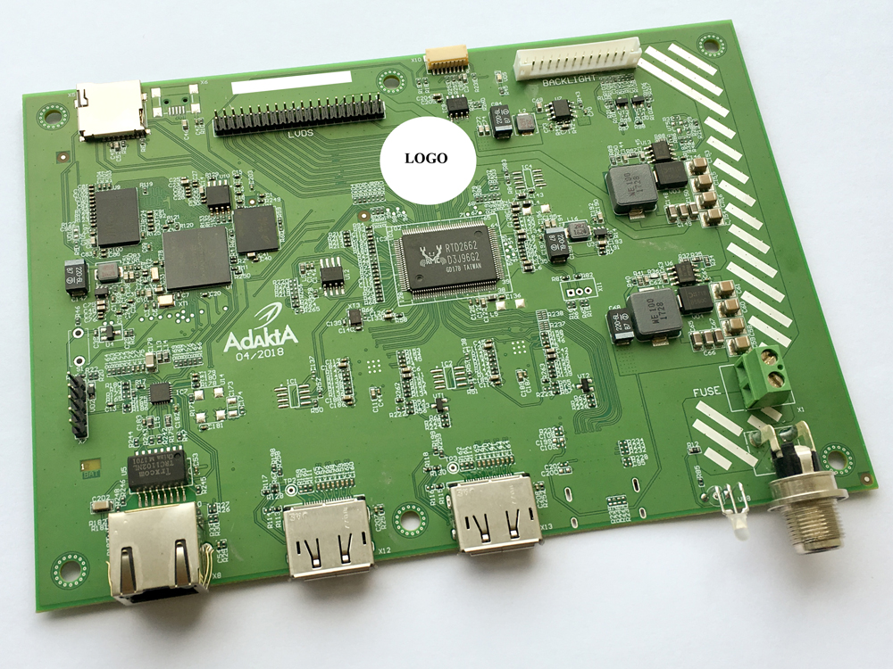
Fig.1. RTD2662
Wiring diagram as in all chassis for TV. The chip is powered by two voltages - 3.3V and 1.8V. It was not possible to find a full-fledged datasheet, and it was not necessary. It was necessary to add only converters from DisplayPort. After a brief search, a Texas Instruments converter - SN75DP139 was chosen. I recommend in development, a good chip. The microcircuits are located on the bottom of the board (I had to do this to avoid cross lines of data, I will probably try to repartition on one side).

Fig.2. The scheme of inclusion SN75DP139
The scheme of inclusion turned out this. For the first time I contacted the DisplayPort interface and for me it was a kind of revelation that the input and output of this interface have different pinouts, that is, it is one on the PC connector, another on the monitor. Although some kind of logic in this is.
Realtek firmware is stored in a separate SPIFlash.
Ethernet 10/100
Ethernet is needed for several things: device monitoring, configuration and upgrade; therefore, 10/100 physics is enough. I put LAN8742AI from Microchip, I used it for the first time, and I chose it, because the customer needed a certain “Wake on LAN” function, before that there was no such need. In a nutshell, WoL support allows you to wake your device over an Ethernet network.

Fig.3. Ethernet 10/100
Physics requires almost no binding and is easy to trace. It works stably, there was not a single fall off of the network.
Lvds
Two channels are needed to connect the matrix AUO 32 ". Connector and pinout used standard. The power supply is 12V, made on DC / DC TPS54560DDAR - this is a great 5A feeder from TI. Illumination matrix 24V, took the input voltage. The matrix has a built-in backlight driver with the ability to adjust on and off. The board is made on 4 layers, so there were no problems with tracing LVSD, HDMI and DisplayPort.

Fig.4. LVDS Trace
As you can see here everything is direct, a slight discrepancy in length does not affect the image quality at all.
KEY
The buttons are implemented on the SX8634 chip from Semtech Corporation - this chip is somewhat ambiguous in its work. Programmers had to cut through the entire driver to get the expected result. It turned out something like this: there are 4 buttons for navigating through the menu, they are sensory (capacitive through glass) with RGB illumination from the inside through the holes in the board. Only the lower button is constantly lit, it also goes into sleep mode and back (with a change of light). When you put your hand on 5cm, the other buttons are highlighted and the menu opposite them pops up. We remove the hand, after 3c the menu disappears, the buttons go out. Looks interesting.

Fig.5. Touch Button Board
The top of the board (top) is adjacent to the glass, so there are no components on it, they are all located on the bottom. The difficulty in setting and calibration was due to the width of the board, it is only 12mm. If it is boring for someone to live, they can use this chip in their projects.
TEMP
The temperature inside the case is measured using the LM75AD temperature sensor from NXP over the I2C bus. It was delivered as it is easy to get it and it is stored in large volumes in warehouses.
WEB
The web interface and the project itself are implemented on the basis of a young engine born by an independent team of 11-parts — our partner in software development for Linux-based systems.
The platform has many blocks, provided with technical support and warranty with the possibility of improvements and updates.
If it is even simpler, this is a framework project with advanced functionality that is constantly improving and enhancing functionality. From the main blocks, you can note the network manager, dynamic WEB interface, update and project collector. Based on the engine, you can implement various devices ranging from an mp3 player to a multi-port 10Gbit SIP server. and this is exactly what we needed in this project.
From the web interface, you can not only control the panel settings, but also change settings, for example, brightness, contrast, image clarity, track which PC is connected to which port and which of them is currently active, switch between them.
Also in this project, support for SNMP 1,2 and 3 versions is supported with support for SET, GET commands and sending traps either by interval or by event. Those. Information about any parameter, for example, brightness / contrast can be transferred to the server via SNMP protocol, by pressing the change parameter button or, for example, every 10 seconds. You can turn off the display or change the parameter remotely using the SNMP SET command. SNMP is also included in the engine.
iMX6ULL
Since the Realtek chip does not have Ethernet onboard, this project uses the NXP iMX6ULL processor, which runs the Linux OS and runs the main logic of the work. iMX and Realtek are interconnected via UART and exchange commands with each other. For quick events there are several GPIO.

Fig.6. iMX6ULL
All information is stored in NAND, the u-boot is booted from SPIFlash. One chip of RAM and nothing more. The SD card is derived for software updates (this is in addition to the ability to do this from the web).
Power
The secondary power supply of 5V is implemented on the same DC / DC as for the matrix power supply - TPS54560DDAR. Power supply 1.8V and 1.35V for AP3418 from Diodes, and 3.3V for ST1S10PHR from ST.
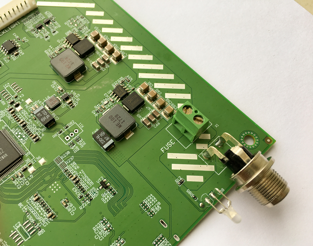
Fig.7. DC / DC
The DC / DC microcircuits were chosen with a large margin, since the matrix had large peak currents in terms of power and illumination, and since there was only one iteration, I really did not want to risk.
All the power supplies are divorced by polygons in a separate layer, with the exception of the matrix supply, since I really did not want to cut the main power supplies with this conductor. Tracing screens is useless, except that someone will be interested in an interface. I also want to give a separate article on food and land ranges, for example, in this project a total of 27 polygons, in my new project on iMX7 there will be about 100, and in the framework of this article it simply does not fit.
If a little more deep into the logic of the board. iMX works with Ethernet and front panel buttons. It is associated with Realtek, which takes the image from the active DisplayPorta and outputs it to the LVDS matrix. Commands from the buttons, SNMP and web fly to Realtek, which in turn reacts to them and changes the display settings, displays the menu, etc.
The result was a rather interesting project in a short time. Probably, it contains too many modules, but at the time of development, in my opinion, this was the best solution in accordance with the timing, costs and risks.
Thanks for attention!