December 24, 2012 at 20:37
A simple in-circuit programmer of ARM microcontrollers of the LPC series do-it-yourself. Circuitry. Part one
Recently, both among professional developers and in the ranks of novice electronics engineers, ARM microcontrollers have become widespread. Developments by NXP are very popular. This company produces a huge range of products - from cheap and low-power to high-performance, supporting such interfaces as USB and Ethernet.
I want to offer my readers my own development, which I personally use, perhaps most often. This is a simple in-circuit programmer that can be easily made with your own hands. The programmer is designed for programming the widespread NXP ARM microcontrollers of the LPC2xxx series. These are microcontrollers with ARM7, Cortex-M0 and Cortex-M3 cores. In addition, it can be used to program low-cost 8-bit microcontrollers from the LPC9xx series, with the exception of the simplest ones from the LPC901 series.
More details about the list can be found here.
www.ru.nxp.com/products/microcontrollers
The programmer connects to a USB port and does not require additional power. It is assembled on just two microcircuits and one transistor.
The device can be used not only for programming a board with a microcontroller, but also for communicating with it via an emulated serial port.

Fig. 1. Schematic diagram of the electrical, part one.
The programmer is assembled on the basis of a FTDI chip - FT232RL
www.ftdichip.com/Products/ICs/FT232R.htm
For successful programming, do not forget to download and install the chip driver that is suitable for your operating system.
Look for it here:
www.ftdichip.com/FTDrivers.htm
Filter L1 can be replaced with a resistor with a resistance of 10 ... 22 Ohms.
LEDs VD1, VD3, resistances R3, R4 can be excluded if the indication of the transmission and reception of data packets via USB is not required.
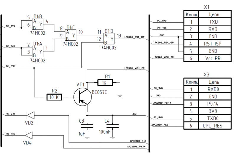
Fig. 2. Schematic diagram of the electrical, part two.
For programming the microcontrollers of the LPC2000 series, the X3 connector is used, for programming the LPC900 X1.
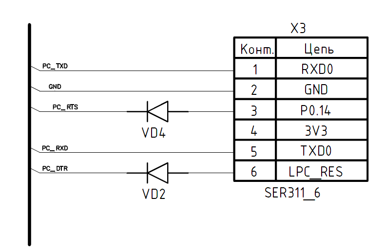
Fig. 3. The electrical circuit diagram, part two for programming microcontrollers of only the LPC2000 series.
LPC900 series microcontrollers are not often used, if you need to program only LPC2000 ARMs, the second part of the circuit can be greatly simplified. The simplified part is shown in Figure 3.

Fig. 4. Wiring diagram.
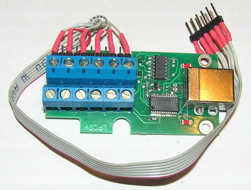
Fig. 5. The appearance of the programmer.
As LEDs, you can use both SMD and output.
As a transistor, almost any direct conductivity suitable for the pinout is suitable.
The list of used parts, the circuit and traces of the board in PCAD 2006 format are located in the attached archive.
docs.google.com/open?id=0B8EEcNDjnzhhUUZJbjc2cEx3NHM
Programming can be done using the free software Flash Magic
www.flashmagictool.com.
I will tell you more about connecting different microcontrollers to the programmer and the in-circuit programming process in the next post .
I want to offer my readers my own development, which I personally use, perhaps most often. This is a simple in-circuit programmer that can be easily made with your own hands. The programmer is designed for programming the widespread NXP ARM microcontrollers of the LPC2xxx series. These are microcontrollers with ARM7, Cortex-M0 and Cortex-M3 cores. In addition, it can be used to program low-cost 8-bit microcontrollers from the LPC9xx series, with the exception of the simplest ones from the LPC901 series.
More details about the list can be found here.
www.ru.nxp.com/products/microcontrollers
The programmer connects to a USB port and does not require additional power. It is assembled on just two microcircuits and one transistor.
The device can be used not only for programming a board with a microcontroller, but also for communicating with it via an emulated serial port.
Fig. 1. Schematic diagram of the electrical, part one.
The programmer is assembled on the basis of a FTDI chip - FT232RL
www.ftdichip.com/Products/ICs/FT232R.htm
For successful programming, do not forget to download and install the chip driver that is suitable for your operating system.
Look for it here:
www.ftdichip.com/FTDrivers.htm
Filter L1 can be replaced with a resistor with a resistance of 10 ... 22 Ohms.
LEDs VD1, VD3, resistances R3, R4 can be excluded if the indication of the transmission and reception of data packets via USB is not required.
Fig. 2. Schematic diagram of the electrical, part two.
For programming the microcontrollers of the LPC2000 series, the X3 connector is used, for programming the LPC900 X1.
Fig. 3. The electrical circuit diagram, part two for programming microcontrollers of only the LPC2000 series.
LPC900 series microcontrollers are not often used, if you need to program only LPC2000 ARMs, the second part of the circuit can be greatly simplified. The simplified part is shown in Figure 3.
Fig. 4. Wiring diagram.
Fig. 5. The appearance of the programmer.
As LEDs, you can use both SMD and output.
As a transistor, almost any direct conductivity suitable for the pinout is suitable.
The list of used parts, the circuit and traces of the board in PCAD 2006 format are located in the attached archive.
docs.google.com/open?id=0B8EEcNDjnzhhUUZJbjc2cEx3NHM
Programming can be done using the free software Flash Magic
www.flashmagictool.com.
I will tell you more about connecting different microcontrollers to the programmer and the in-circuit programming process in the next post .