How to find PCI devices without an operating system
In the course of work, we periodically have to deal with a fairly low-level interaction with the hardware. In this article, we want to show how the interrogation of PCI devices is done to identify them and load the corresponding device drivers.
As a minimum base for working with PCI devices, we will use a kernel that supports the Multiboot specification. This avoids the need to write your own boot sector and loader. In addition, this issue is already well covered on the Internet. The boot loader will be GRUB. We will boot from the flash drive, since it is convenient to boot both the virtual and the real machine from it. We will use QEMU as a virtual machine. A real machine should be a machine with a normal BIOS (not UEFI) that supports booting from USB-HDD (usually there is the Legacy USB support option). To work, you will need Ubuntu Linux with the following programs: expect, qemu, grub (they can be easily installed using the sudo apt-get install command). The gcc used should compile 32 bit code.
Consider the first step - creating a kernel that supports the Multiboot specification. If GRUB is used as a loader, the kernel will be created from 3 files:
Kernel.c - the main file with our program code and the main () procedure;
Loader.s - contains the multiboot header for GRUB;
Linker.ld is an ld linker script that specifically indicates at which address the kernel will be located.
Linker.ld Content:
The linker script indicates how to link already compiled object files. The first line indicates that the entry point in our core will be the address labeled “loader”. Further in the script it is indicated that starting from the address 0x00100000 (1Mb) the text section will be located. The rodata, data, and bss sections are aligned to 0x1000 (4Kb) and are located after the text section.
Contents of Loader.s:
GRUB after loading the kernel image from the disk looks for the signature 0x1BADB002 in the first 8Kb of the downloaded image. The signature is the first multiboot header field. The title itself is as follows:
The title should include at least 3 fields - magic, flag, checksum. The magic field is a signature and, as mentioned above, is always 0x1BADB002. The flag field contains additional requirements for the state of the machine at the time of transfer of control to the OS. Depending on the value of this field, the set of fields in the Multiboot Information structure may change. A pointer to the Multiboot Information structure contains the EBX register at the time of transfer of control to the loaded kernel. In our case, the flag field has a value of 0, and the multiboot header consists of only 3 fields.
At the time of transferring control to the kernel, the processor is in protected mode with paging disabled. Device interrupt handling is disabled. GRUB does not form a stack for a bootable kernel, and this is the first thing the operating system should do. In our case, 16KB is allocated under the stack. The last assembler statement executed is the call kmain statement, which transfers control to the C code, namely the void kmain (void) function.
The contents of kernel.c:
There is nothing interesting here yet. From the point of view of loading, nothing specific should be present in it, only an entry point for the C code. To display the implementation of the printf function found on the Internet, and several functions for working with video memory, such as putchar, clear_screen, were added.
The following simple makefile will be used to build the kernel:
Now we have a kernel that can be downloaded. It's time to check that it really loads. Install GRUB on a USB flash drive and tell it to load our kernel at startup. To do this, follow these steps:
1. Create a partition on a USB flash drive, format it into a file system supported by GRUB (in our case, it is a FAT32 file system). We used the Disk Utility utility from the Ubuntu bundle, which allowed us to create a partition:

2. Mount a USB flash drive and create a directory / boot / grub /. Copy the files stage1, stage2, fat_stage1_5 into / usr / lib into it. Create a text file menu.lst in the directory / boot / grub / and write to it
To install GRUB on a USB flash drive, use the expect script in the grub_install.exp file. Its contents:
In a specific case, other drive numbers and device names are possible. Ultimately, compiling and starting the virtual machine must be done with the make start command. This command from makefile will install GRUB on a flash drive using the grub_install.exp script, and then start the QEMU virtual machine with our program. Since everything is loaded from a real flash drive, it is possible to boot from it not only the QEMU virtual machine, but also a real computer.
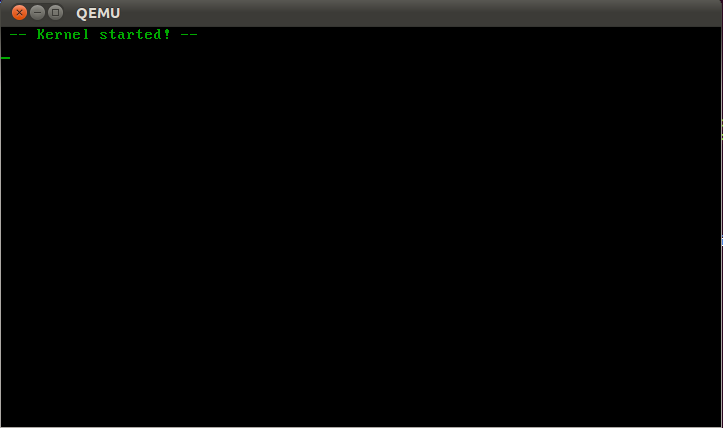
The launched QEMU virtual machine with our program is as follows:
Now let's get down to the main task - listing all the PCI devices available on the computer. PCI is the main bus with devices on the computer. In addition to conventional devices that are inserted into the well-known slots on the motherboard, it also includes devices wired into the motherboard itself (the so-called On-board devices), as well as a number of controllers (for example, USB) and bridges to other buses ( e.g. PCI-ISA bridge). Thus, PCI is the main bus on the computer, from which the interrogation of all its devices begins.
Each PCI-device is associated with a structure of 256 bytes (PCI Configuration Space), in which its settings are located. The configuration of the device ultimately comes down to writing and reading data from this structure. For all PCI devices, data is read and written through 2 input-output ports:
0xcf8 - configuration port, into which the PCI address is written;
0xcfc - data port through which data is read and written to the PCI address specified in the configuration port.
When reading data from the PCI Configuration Space, you can get information about the device, and writing data to the device can be configured.
The PCI address is the following 32-bit structure:
The bus number along with the device number identifies the physical device on the computer. A physical device may include several logical ones that are identified by a function number (for example, a video capture card with a Wi-Fi controller will have at least two functions).
PCI Configuration Space is conditionally divided into registers of 4 bytes. The register number that is being accessed is stored from the 2nd to the 7th bits in a 32-bit PCI address. The fields in the PCI Configuration Space structure describing a PCI device depend on its type. But for all types of devices, the first 4 registers of the structure contain the following fields:
Class code - describes the type (class) of the device in terms of the functions that the device performs (network adapter, video card, etc.);
Vendor ID - device manufacturer identifier (each device manufacturer in the world has one or more of these unique identifiers). These numbers are issued by PCI SIG;
Device ID - a unique device identifier (unique to the specified Vendor ID). Their numbering is determined by the manufacturer.
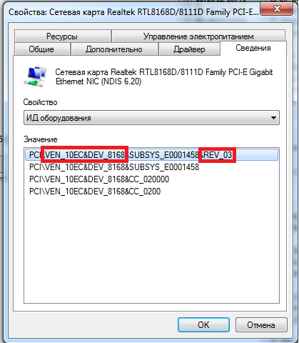
The fields DeviceID (abbreviated DEV) and VendorID (abbreviated VEN) determine the driver corresponding to this device. Sometimes for this an additional identifier RevisionID (abbreviated REV) is used. In other words, Windows, when it detects a new device in the computer, uses the numbers VEN, DEV, and REV to search for the corresponding drivers on its disk or on the Internet using Microsoft servers. You can also find these numbers in the device manager:
Consider a code that implements the easiest way to obtain a list of PCI devices on a computer:
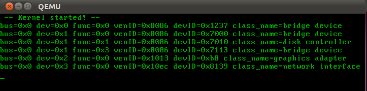
In this code, the bus numbers and device numbers are completely enumerated in the address at which the reading takes place. If the Header type field contains the PCI_HEADERTYPE_MULTIFUNC flag, then this physical device implements several logical devices, and when searching for PCI-devices in the address written to the configuration port, you need to iterate over the function number. If VendorID is incorrect, then there is no device with this number on this bus. On Qemu, this code displays the following result:
0x8086 is the Intel VendorID hardware. A DeviceID of 0x7000 corresponds to a PIIX3 PCI-to-ISA Bridge device. Boot from the resulting flash drive into VmWare Workstation 9.0. The list of PCI devices turned out to be much longer and looks as follows:

This is how the search for PCI devices in the system looks like. This action is performed on all modern operating systems running on IBM PC computers. The next step in the operation of the operating system is to search for drivers and configure the devices found, and this is already happening in a unique way for each device individually.
As a minimum base for working with PCI devices, we will use a kernel that supports the Multiboot specification. This avoids the need to write your own boot sector and loader. In addition, this issue is already well covered on the Internet. The boot loader will be GRUB. We will boot from the flash drive, since it is convenient to boot both the virtual and the real machine from it. We will use QEMU as a virtual machine. A real machine should be a machine with a normal BIOS (not UEFI) that supports booting from USB-HDD (usually there is the Legacy USB support option). To work, you will need Ubuntu Linux with the following programs: expect, qemu, grub (they can be easily installed using the sudo apt-get install command). The gcc used should compile 32 bit code.
Consider the first step - creating a kernel that supports the Multiboot specification. If GRUB is used as a loader, the kernel will be created from 3 files:
Kernel.c - the main file with our program code and the main () procedure;
Loader.s - contains the multiboot header for GRUB;
Linker.ld is an ld linker script that specifically indicates at which address the kernel will be located.
Linker.ld Content:
ENTRY (loader)
SECTIONS
{
    . = 0x00100000;
    .text ALIGN (0x1000) :
    {
        *(.text)
    }
    .rodata ALIGN (0x1000) :
    {
        *(.rodata*)
    }
    .data ALIGN (0x1000) :
    {
        *(.data)
    }
    .bss :
    {
        sbss = .;
        *(COMMON)
        *(.bss)
        ebss = .;
    }
}
The linker script indicates how to link already compiled object files. The first line indicates that the entry point in our core will be the address labeled “loader”. Further in the script it is indicated that starting from the address 0x00100000 (1Mb) the text section will be located. The rodata, data, and bss sections are aligned to 0x1000 (4Kb) and are located after the text section.
Contents of Loader.s:
.global loader
.set FLAGS,    0x0
.set MAGIC,    0x1BADB002
.set CHECKSUM, -(MAGIC + FLAGS)
.align 4
.long MAGIC
.long FLAGS
.long CHECKSUM
# reserve initial kernel stack space
.set STACKSIZE, 0x4000
.lcomm stack, STACKSIZE
.comm  mbd, 4
.comm  magic, 4
loader:
    movl  $(stack + STACKSIZE), %esp
    movl  %eax, magic
    movl  %ebx, mbd
    call  kmain
    cli
hang:
    hlt
    jmp   hang
GRUB after loading the kernel image from the disk looks for the signature 0x1BADB002 in the first 8Kb of the downloaded image. The signature is the first multiboot header field. The title itself is as follows:
| Offset | Type | Field name | Note |
| 0 | u32 | magic | required |
| 4 | u32 | flags | required |
| 8 | u32 | checksum | required |
| 12 | u32 | header_addr | if flags [16] is set |
| 16 | u32 | load_addr | if flags [16] is set |
| 20 | u32 | load_end_addr | if flags [16] is set |
| 24 | u32 | bss_end_addr | if flags [16] is set |
| 28 | u32 | entry_addr | if flags [16] is set |
| 32 | u32 | mode_type | if flags [2] is set |
| 36 | u32 | width | if flags [2] is set |
| 40 | u32 | height | if flags [2] is set |
| 44 | u32 | depth | if flags [2] is set |
The title should include at least 3 fields - magic, flag, checksum. The magic field is a signature and, as mentioned above, is always 0x1BADB002. The flag field contains additional requirements for the state of the machine at the time of transfer of control to the OS. Depending on the value of this field, the set of fields in the Multiboot Information structure may change. A pointer to the Multiboot Information structure contains the EBX register at the time of transfer of control to the loaded kernel. In our case, the flag field has a value of 0, and the multiboot header consists of only 3 fields.
At the time of transferring control to the kernel, the processor is in protected mode with paging disabled. Device interrupt handling is disabled. GRUB does not form a stack for a bootable kernel, and this is the first thing the operating system should do. In our case, 16KB is allocated under the stack. The last assembler statement executed is the call kmain statement, which transfers control to the C code, namely the void kmain (void) function.
The contents of kernel.c:
#include "printf.h"
#include "screen.h"
void kmain(void)
{
	clear_screen();
	printf(" -- Kernel started! -- \n");
}
There is nothing interesting here yet. From the point of view of loading, nothing specific should be present in it, only an entry point for the C code. To display the implementation of the printf function found on the Internet, and several functions for working with video memory, such as putchar, clear_screen, were added.
The following simple makefile will be used to build the kernel:
CC	= gcc
CFLAGS	= -Wall -nostdlib -fno-builtin -nostartfiles -nodefaultlibs
LD	= ld
OBJFILES = \
	loader.o  \
	printf.o  \
	screen.o  \
	pci.o  \
	kernel.o
start: all
	cp ./kernel.bin ./flash/boot/grub/
	expect ./grub_install.exp
	qemu /dev/sdb
all: kernel.bin
.s.o:
	as -o $@ $<
.c.o:
	$(CC) $(CFLAGS) -o $@ -c $<
kernel.bin: $(OBJFILES)
	$(LD) -T linker.ld -o $@ $^
clean:
	rm $(OBJFILES) kernel.bin
Now we have a kernel that can be downloaded. It's time to check that it really loads. Install GRUB on a USB flash drive and tell it to load our kernel at startup. To do this, follow these steps:
1. Create a partition on a USB flash drive, format it into a file system supported by GRUB (in our case, it is a FAT32 file system). We used the Disk Utility utility from the Ubuntu bundle, which allowed us to create a partition:
2. Mount a USB flash drive and create a directory / boot / grub /. Copy the files stage1, stage2, fat_stage1_5 into / usr / lib into it. Create a text file menu.lst in the directory / boot / grub / and write to it
timeout   5
default   0
title  start_kernel
root   (hd0,0)
kernel /boot/grub/kernel.bin
To install GRUB on a USB flash drive, use the expect script in the grub_install.exp file. Its contents:
log_user 0
spawn grub
expect "grub> "
send "root (hd1,0)\r"
expect "grub> "
send "setup (hd1)\r"
expect "grub> "
send "quit\r"
exit 0
In a specific case, other drive numbers and device names are possible. Ultimately, compiling and starting the virtual machine must be done with the make start command. This command from makefile will install GRUB on a flash drive using the grub_install.exp script, and then start the QEMU virtual machine with our program. Since everything is loaded from a real flash drive, it is possible to boot from it not only the QEMU virtual machine, but also a real computer.
The launched QEMU virtual machine with our program is as follows:
Now let's get down to the main task - listing all the PCI devices available on the computer. PCI is the main bus with devices on the computer. In addition to conventional devices that are inserted into the well-known slots on the motherboard, it also includes devices wired into the motherboard itself (the so-called On-board devices), as well as a number of controllers (for example, USB) and bridges to other buses ( e.g. PCI-ISA bridge). Thus, PCI is the main bus on the computer, from which the interrogation of all its devices begins.
Each PCI-device is associated with a structure of 256 bytes (PCI Configuration Space), in which its settings are located. The configuration of the device ultimately comes down to writing and reading data from this structure. For all PCI devices, data is read and written through 2 input-output ports:
0xcf8 - configuration port, into which the PCI address is written;
0xcfc - data port through which data is read and written to the PCI address specified in the configuration port.
When reading data from the PCI Configuration Space, you can get information about the device, and writing data to the device can be configured.
The PCI address is the following 32-bit structure:
| Bit 31 | Bits 30 - 24 | Bits 23 - 16 | Bits 15 - 11 | Bits 10 - 8 | Bits 7 - 2 | Bits 1 - 0 |
| Always 1 | Reserved | Tire number | Device number | Function number | Register number | Always 0 |
The bus number along with the device number identifies the physical device on the computer. A physical device may include several logical ones that are identified by a function number (for example, a video capture card with a Wi-Fi controller will have at least two functions).
PCI Configuration Space is conditionally divided into registers of 4 bytes. The register number that is being accessed is stored from the 2nd to the 7th bits in a 32-bit PCI address. The fields in the PCI Configuration Space structure describing a PCI device depend on its type. But for all types of devices, the first 4 registers of the structure contain the following fields:
| Register number | Bits 31 - 24 | Bits 23 - 16 | Bits 15 - 8 | Bits 7 - 0 |
| 0 | Device id | Vendor id | ||
| 1 | Status | Command | ||
| 2 | Class code | Subclass | Prog IF | Revision id |
| 3 | Bist | Header type | Latency timer | Cache line size |
Class code - describes the type (class) of the device in terms of the functions that the device performs (network adapter, video card, etc.);
Vendor ID - device manufacturer identifier (each device manufacturer in the world has one or more of these unique identifiers). These numbers are issued by PCI SIG;
Device ID - a unique device identifier (unique to the specified Vendor ID). Their numbering is determined by the manufacturer.
The fields DeviceID (abbreviated DEV) and VendorID (abbreviated VEN) determine the driver corresponding to this device. Sometimes for this an additional identifier RevisionID (abbreviated REV) is used. In other words, Windows, when it detects a new device in the computer, uses the numbers VEN, DEV, and REV to search for the corresponding drivers on its disk or on the Internet using Microsoft servers. You can also find these numbers in the device manager:
Consider a code that implements the easiest way to obtain a list of PCI devices on a computer:
int ReadPCIDevHeader(u32 bus, u32 dev, u32 func, PCIDevHeader *p_pciDevice)
{
	int i;
	if (p_pciDevice == 0)
		return 1;
	for (i = 0; i < sizeof(p_pciDevice->header)/sizeof(p_pciDevice->header[0]); i++)
		ReadConfig32(bus, dev, func, i, &p_pciDevice->header[i]);
	if (p_pciDevice->option.vendorID == 0x0000 ||
		p_pciDevice->option.vendorID == 0xffff ||
		p_pciDevice->option.deviceID == 0xffff)
		return 1;
	return 0;
}
void kmain(void)
{
	int bus;
	int dev;
	clear_screen();
	printf(" -- Kernel started! -- \n");
	for (bus = 0; bus < PCI_MAX_BUSES; bus++)
		for (dev = 0; dev < PCI_MAX_DEVICES; dev++)
		{
			u32 func = 0;
			PCIDevHeader pci_device;
			if (ReadPCIDevHeader(bus, dev, func, &pci_device))
				continue;
			PrintPCIDevHeader(bus, dev, func, &pci_device);
			if (pci_device.option.headerType & PCI_HEADERTYPE_MULTIFUNC)
			{
				for (func = 1; func < PCI_MAX_FUNCTIONS; func++)
				{
					if (ReadPCIDevHeader(bus, dev, func, &pci_device))
						continue;
					PrintPCIDevHeader(bus, dev, func, &pci_device);
				}
			}
		}
}
In this code, the bus numbers and device numbers are completely enumerated in the address at which the reading takes place. If the Header type field contains the PCI_HEADERTYPE_MULTIFUNC flag, then this physical device implements several logical devices, and when searching for PCI-devices in the address written to the configuration port, you need to iterate over the function number. If VendorID is incorrect, then there is no device with this number on this bus. On Qemu, this code displays the following result:
0x8086 is the Intel VendorID hardware. A DeviceID of 0x7000 corresponds to a PIIX3 PCI-to-ISA Bridge device. Boot from the resulting flash drive into VmWare Workstation 9.0. The list of PCI devices turned out to be much longer and looks as follows:
This is how the search for PCI devices in the system looks like. This action is performed on all modern operating systems running on IBM PC computers. The next step in the operation of the operating system is to search for drivers and configure the devices found, and this is already happening in a unique way for each device individually.