Non-binary logic
At the beginning of World War II, the US army was faced with the acute problem of the lack of ballistic shooting tables, vital for the operation of artillery. A typical ballistic table is a set of numerical data on projectile flight paths, previously calculated for specific firing conditions, barrel, projectile, weather conditions and air temperature. Manual calculation of only one trajectory took several days, and each table cost a huge amount of man-hours.
At that time, only a few highly qualified specialists were involved in these calculations, and even an increase in the laboratory staff in 1942 helped little. In June of the same year, a contract was signed with the Moore School of Electrical Engineering at the University of Pennsylvania, which had a Vanivar Bush differential design analyzer - a mechanical computer of that era. The work was led by a lieutenant, and later by captain Herman Goldstein, who received a doctorate in mathematics from the University of Chicago. It was he, with Professor Brynerd, who introduced the idea of the "electronic differential analyzer" by John Mockley in 1943.
The new machine, the design of which was rejected a year earlier for excessive novelty, began to do real work only in the fall of 1945. Mokley, who previously worked with weather and physical data, foresaw the future urgent need for a high-speed computer, and although by the time construction was completed, there was no need to make ballistic tables, the computer was in demand and was used in the design of a nuclear and thermonuclear bomb, weather calculations, and radioactive fallout , solving the problem of supersonic aircraft engineering and in the calculation of mathematical constants.
With its general primitiveness (it was necessary to manually move nodes and switches to set the program) and technical difficulties of operation associated with the unreliability of vacuum tubes, ENIAK impressed with its capabilities and speed, which was not limited by the presence of moving parts. Unlike other electromechanical machines of that era, which operated on electric relays, and their successor EDVAC, the first general-purpose electronic digital computer was not binary, but decimal.

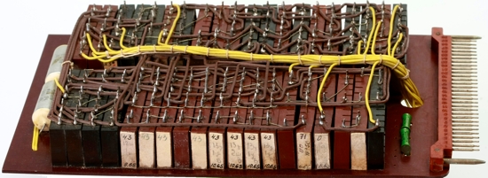
Decimal drives of the computer ENIAK
The choice of the decimal system was dictated by questions of ease of use; the creators of the machine decided to neglect the merits of other number systems. ENIAK could add, subtract, multiply, divide, extract the square root and compare any decimal numbers of 10 digits. In the memory of 20 drives, which were also adders, up to 20 such numbers could be stored. Moreover, the numbers were not represented by ten different electrical values that could easily change, but by the absence or presence of active pulses, and a set of signals of the same number was transmitted together via several different wires. Thus, 11 lines (10 digits and a sign) approached each register.
Each trigger of the machine had two inputs and two outputs and contained two triodes connected in such a way that at any given time the current passed through only one. Ten triggers formed a decimal ring capable of counting numerical signals and storing numbers. In turn, ten rings were combined into a basic arithmetic drive. If one of the rings exceeded the limit of 9 values, the senior neighbor received an additional impulse.
The computer, which was essentially a mechanically programmable calculator, relied on these drives in its work. When adding one of the drives passed the digits of the corresponding digits to the other, when subtracting, it took it. For multiplication, four storage devices were required that store the multiplier, the multiplicand, and two cells for performing the mathematical operation. When dividing, the dividend, divisor, quotient, and remainder were stored, shifted by digits to subtract from the dividend.
It is obvious that ENIAC was largely hardware redundant. Its complexity caused by the use of such a “human” decimal form for representing numbers on the basis of binary triggers, and the instability in the operation of vacuum tubes somewhat impeded its work and forced the staff to take various tricks in its operation.
The last upgrade of the car took place in July 1953 (before this, ENIAK acquired, for example, a mechanical power decoupling system). Already in 1951, the question arose of insufficient memory, and Burroughs Corporation proposed the use of promising technology of magnetic cells. The main problem of the performer was the language. To implement a memory of 100 words in ENIAC, each of which was 10 decimal digits and 10 characters of these numbers, 9.100 bits of storage would be required. Instead, each digit was presented in the form of 4 bits with the introduction of code converters, but even taking into account the lost bits of forbidden states, the savings were significant - it took only 4,100 bits.
ENIAK was followed by a series of machines from IBM, UNIVAC, and others, but decimal computers were gradually replaced by binary ones. The reasons for this are simple: the elementary logical elements that are common today have only two states that they can accept, so writing binary data is obviously simpler and denser. Sixty years later, moving away from binary logic is perceived as a knowingly losing step, but is binary logic mathematically the best choice?
The specific natural log density of information is described by the function
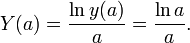
This function reaches a maximum at a = e. This means that the calculus system with the base equal to the base of the natural logarithms (e ≈ 2.718281828459045) has the highest information recording density. That is how the base was chosen for fixing the logarithmic tables. Moreover, of integer number systems, the ternary rather than the binary calculus has the highest information recording density.
The ternary number system exists in two versions: symmetric, having negative digits (−1, 0, 1) in the set, and asymmetric (0, 1, 2). It should be noted that the ternary symmetric number system has the property that provides a simpler representation of negative numbers in the computer's memory. (As you know, for this, you need to enter additional code in order not to complicate the architecture of the computer.)
The ternary computer operates with ternary logic, the first and most famous multi-valued logic. Unlike binary logic, where a statement is assigned a value of either "true" or "false", the ternary fuzzy logic has a state of "unknown". The advantage of a three-valued logic over a binary one is most easily demonstrated by the example of the operation of comparing two numbers: here the ternary logic immediately gives the result (more, less or equal), and the binary answer requires first finding out if the first is greater than the second, and then make sure whether the second is greater than first.
Not all laws of binary logic are true for ternary logic; for some, ternary analogues are formulated. A number of researchers have appealed to the fact that three-valued logic is much more natural and characteristic of human thinking than binary. Today, stagnant binary logic, according to their statements, does not allow us to enter a three-digit one. The development of ternary logic at different periods of time was engaged in by the Polish philosopher and logician Jan Lukasevich, the English mathematician Lewis Carroll and others.
Despite all the advantages of ternary logic and ternary number system, in the history of mankind there are only two of the most successful attempts to create a ternary computer. The first of them - mechanical - dates from the 19th century. Fowler's wooden calculator used a symmetric ternary number system, and Augustus de Morgan made the most accurate description for him today, on the basis of which the machine was recreated.
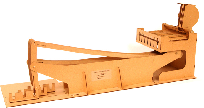
Fearing the theft of his ideas, Fowler alone performed wood parts. In order to compensate for the low accuracy caused by it, the inventor gave his machine large dimensions - 1.80 meters in length, 90 cm in depth and 30 cm in height. Prior to this, Fowler developed methods for working with the number system used in his machine.
The machine consists of four parts. Depending on the operation performed, the first part (highlighted in red in the figure) represents a multiplicative or quotient, the second (highlighted in blue) is a factor or divisor, the third (highlighted in burgundy) is a product or dividend, and the fourth is a transfer machine that simplifies the answer to its simplest forms after performing basic operations and can be moved for this to a multiplier or divider to work with them.
A multiplier is a frame that can move perpendicular to the rods of the multiplicand and the product, and is located between their planes in such a way that its edge can be combined with a sliding movement with each rod of the multiplicative in turn. The multiplier consists of a set of rods, with each of the rods having a tooth from each edge and a tooth with which the multiplier interacts with the rods of the multiplier. One set of teeth is placed so that it rests on a frame that can rotate around an axis. Each rod may be in contact with the frame above, below, or in the region of the axis of rotation. The teeth located on the axis do not receive movement, the rest will move in one direction or another, depending on which side the tooth touches the frame. Perpendicular teeth from the other end can move forward-backward or remain motionless,

When multiplying, the frame of the multiplier is set so that the edge of the multiplier coincides with the first rod of the multiplier. A tooth is fixed from the edge, which engages with the rod of the multiplier over which it turned out, moving it in one direction or another according to which direction the frame of the multiplier can turn. Then the rotating frame must be moved in such a way that the core of the multiplicable hits zero. So the discharge of the multiplier with the factor is multiplied. Then the impact of perpendicular teeth displays the result on the frame of the work. The frame of the factor is shifted until the tooth is above the next rod of the multiplier, after which the tooth is shifted so as to shift the next rod of the multiplier to the zero position. The next digit of the multiplier will be multiplied by a factor, and the frame of the product will receive and add it. Operation is repeated as long
The result of the multiplication will not be presented in the simplest form: it should contain only +1 or −1, and the received intermediate answer may contain +2, −2, +3 or −3 on any rod, etc. To adjust the result, a transfer mechanism is used, which is a simple device that, like the multiplier, can perform lateral movement, and can be placed on any pair of adjacent rods. The transfer device extends the left of the two rods by one and retracts the rod on the right by 3 units or vice versa. Even without the required skill of working with the transfer mechanism, a serious mistake is impossible, since for each operation you can transfer the bottom column by only 3 units, while the next column will change in the opposite direction by one unit.
The division of numbers is carried out in the opposite way.
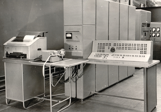
The second most successful project of a ternary computer is a relatively modern serial (50 copies) Setun computer, built at the MSU computer center in 1959. Its creator is the Soviet designer Nikolai Petrovich Brusentsov, also E.A. Zhogolev, V.V. Verigin, S.P. Maslov, A.M. Tishulin and others. The machine used a symmetric ternary number system.
The minimum addressable unit of the “Setuni” memory was a trait equal to six trits and taking values from -364 to 364. Working with the negative value range is a feature that distinguishes trait from a binary byte, the values of which are distributed from 0 to 255. Using the trait, you can encode everything uppercase and lowercase characters of the Russian and Latin alphabets, the necessary mathematical and auxiliary characters.
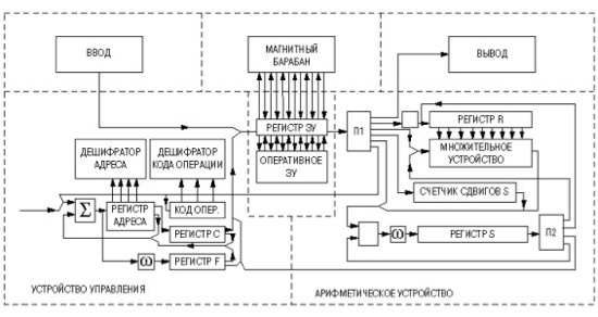
The machine was implemented not on unreliable vacuum tubes or transistors expensive in that era, but on ferrite-diode elements assembled on a getinax basis. The clock generator set the clock cycle of the cells at 200 kHz. The cells were arranged in functional blocks: adders, ternary code decoders, shift registers. Using a thirty-pin connector, each unit docked with the other Setuni units, forming the basic computer components: an arithmetic device and a control device
During the design, Brusentsov borrowed the principle of operation of logic elements from the LEM-1 computer, but while the latter uses a pair of cores for each bit - working and compensation, the compensation core also works in Setun, which sets the ternary nature of the computer. In the Brusentsov ternary cell, one trit was recorded in two binary digits, the fourth state of two binary digits was not used.
The first prototype of the Setun machine showed 95% of the useful time during testing (real work outside testing, maintenance and troubleshooting), while 60% was considered a good result. Due to uncomplicated technologies, “Setun” with all its peripherals cost 27.5 thousand rubles (for comparison: only the processor unit of the record cheap PDP-8 cost $ 20 thousand), and they showed interest in the car not only in the socialist countries, but also in the West. The Czechoslovak Zbroevka Jan Schwermy factory was ready to start production of a car for buyers abroad and promised a profit of half a million dollars from each machine, but higher management required first to launch a mass production of the car in the USSR, although even then it was obvious that the project was closer to closing.
And the project was really closed. In 1967, when it was decided to make various production gifts, designers, some of which had already changed jobs, on the 100th anniversary of Lenin’s birthday, they committed to make “Setun-70”, an improved version of the original, by this date. It was a slightly different computer: it was a stack, but unlike Elbrus with its operand stack and later PDP-11 with its procedural stack, Setun-70 had two stacks — commands and operands. According to Brusentsov himself, the programs on Setun-70 turned out to be easy to read and learn, and instead of debugging, a control assembly was used - the passage of the written code from the bottom up. Later, “Setun-70” was emulated on binary machines in the form of a dialog system for structural programming of DSSPbut the developers, having the bitter experience of Setun, naturally did not make attempts to replicate Setun-70.
One should not think that today the ternary logic has been completely forgotten: it is used in telecommunications, where information transfer speeds are important. Sending one trit per clock cycle increases the data transfer rate by one bit by 1.5 times by one bit, with an increase in the number of bits the speed grows exponentially, while the specific hardware costs decrease.
IBM, Motorola, Hypres, and Texas Instruments conduct various research in the field of ternary computers. Significant hardware problems in the implementation of three-valued logic do not exist today; on the contrary, new and promising elements with three states are proposed. Within the framework of silicon-germanium alloys (SiGe), it is possible to implement digital integrated circuits working with three or more signal levels.
In his scientific work “ Architecture of a ternary optical computer"Gene Yi, Hee Huakan and Lu Yangtian suggest using two states of polarization of light with orthogonal directions of oscillations to express information. Three researchers propose using a fiber optic ring as a register, a semiconductor memory for a ternary cell, and liquid crystals as modulators and adders.
It should be remembered about the whole complex of ternary logic flaws. For example, logical elements with three states will cost more, and designing a computer based on them will be fraught with various difficulties.
For the productive work of the ternary computer, a lot of high-quality ternary software is needed, which does not exist now. To date, several thousand person-years and billions of dollars have been spent on some binary software projects, and to recreate from scratch something like this for three-digit logic would be too expensive a solution.
Otherwise, the ternary computer is mathematically the best solution, and the features of its logic, as well as the representation of negative numbers speak of this. It is hoped that our attitude towards ternary logic will change over time.
In preparing the publication, materials from the monograph Electronic Computers in the Artillery Troops , mortarti.com sites, were used .trinary.ru , trinitas.ru , Computerra magazine and archives of Moscow State University .
At that time, only a few highly qualified specialists were involved in these calculations, and even an increase in the laboratory staff in 1942 helped little. In June of the same year, a contract was signed with the Moore School of Electrical Engineering at the University of Pennsylvania, which had a Vanivar Bush differential design analyzer - a mechanical computer of that era. The work was led by a lieutenant, and later by captain Herman Goldstein, who received a doctorate in mathematics from the University of Chicago. It was he, with Professor Brynerd, who introduced the idea of the "electronic differential analyzer" by John Mockley in 1943.
The new machine, the design of which was rejected a year earlier for excessive novelty, began to do real work only in the fall of 1945. Mokley, who previously worked with weather and physical data, foresaw the future urgent need for a high-speed computer, and although by the time construction was completed, there was no need to make ballistic tables, the computer was in demand and was used in the design of a nuclear and thermonuclear bomb, weather calculations, and radioactive fallout , solving the problem of supersonic aircraft engineering and in the calculation of mathematical constants.
With its general primitiveness (it was necessary to manually move nodes and switches to set the program) and technical difficulties of operation associated with the unreliability of vacuum tubes, ENIAK impressed with its capabilities and speed, which was not limited by the presence of moving parts. Unlike other electromechanical machines of that era, which operated on electric relays, and their successor EDVAC, the first general-purpose electronic digital computer was not binary, but decimal.
Decimal drives of the computer ENIAK
The choice of the decimal system was dictated by questions of ease of use; the creators of the machine decided to neglect the merits of other number systems. ENIAK could add, subtract, multiply, divide, extract the square root and compare any decimal numbers of 10 digits. In the memory of 20 drives, which were also adders, up to 20 such numbers could be stored. Moreover, the numbers were not represented by ten different electrical values that could easily change, but by the absence or presence of active pulses, and a set of signals of the same number was transmitted together via several different wires. Thus, 11 lines (10 digits and a sign) approached each register.
Each trigger of the machine had two inputs and two outputs and contained two triodes connected in such a way that at any given time the current passed through only one. Ten triggers formed a decimal ring capable of counting numerical signals and storing numbers. In turn, ten rings were combined into a basic arithmetic drive. If one of the rings exceeded the limit of 9 values, the senior neighbor received an additional impulse.
The computer, which was essentially a mechanically programmable calculator, relied on these drives in its work. When adding one of the drives passed the digits of the corresponding digits to the other, when subtracting, it took it. For multiplication, four storage devices were required that store the multiplier, the multiplicand, and two cells for performing the mathematical operation. When dividing, the dividend, divisor, quotient, and remainder were stored, shifted by digits to subtract from the dividend.
It is obvious that ENIAC was largely hardware redundant. Its complexity caused by the use of such a “human” decimal form for representing numbers on the basis of binary triggers, and the instability in the operation of vacuum tubes somewhat impeded its work and forced the staff to take various tricks in its operation.
The last upgrade of the car took place in July 1953 (before this, ENIAK acquired, for example, a mechanical power decoupling system). Already in 1951, the question arose of insufficient memory, and Burroughs Corporation proposed the use of promising technology of magnetic cells. The main problem of the performer was the language. To implement a memory of 100 words in ENIAC, each of which was 10 decimal digits and 10 characters of these numbers, 9.100 bits of storage would be required. Instead, each digit was presented in the form of 4 bits with the introduction of code converters, but even taking into account the lost bits of forbidden states, the savings were significant - it took only 4,100 bits.
ENIAK was followed by a series of machines from IBM, UNIVAC, and others, but decimal computers were gradually replaced by binary ones. The reasons for this are simple: the elementary logical elements that are common today have only two states that they can accept, so writing binary data is obviously simpler and denser. Sixty years later, moving away from binary logic is perceived as a knowingly losing step, but is binary logic mathematically the best choice?
The specific natural log density of information is described by the function
This function reaches a maximum at a = e. This means that the calculus system with the base equal to the base of the natural logarithms (e ≈ 2.718281828459045) has the highest information recording density. That is how the base was chosen for fixing the logarithmic tables. Moreover, of integer number systems, the ternary rather than the binary calculus has the highest information recording density.
The ternary number system exists in two versions: symmetric, having negative digits (−1, 0, 1) in the set, and asymmetric (0, 1, 2). It should be noted that the ternary symmetric number system has the property that provides a simpler representation of negative numbers in the computer's memory. (As you know, for this, you need to enter additional code in order not to complicate the architecture of the computer.)
The ternary computer operates with ternary logic, the first and most famous multi-valued logic. Unlike binary logic, where a statement is assigned a value of either "true" or "false", the ternary fuzzy logic has a state of "unknown". The advantage of a three-valued logic over a binary one is most easily demonstrated by the example of the operation of comparing two numbers: here the ternary logic immediately gives the result (more, less or equal), and the binary answer requires first finding out if the first is greater than the second, and then make sure whether the second is greater than first.
Not all laws of binary logic are true for ternary logic; for some, ternary analogues are formulated. A number of researchers have appealed to the fact that three-valued logic is much more natural and characteristic of human thinking than binary. Today, stagnant binary logic, according to their statements, does not allow us to enter a three-digit one. The development of ternary logic at different periods of time was engaged in by the Polish philosopher and logician Jan Lukasevich, the English mathematician Lewis Carroll and others.
Despite all the advantages of ternary logic and ternary number system, in the history of mankind there are only two of the most successful attempts to create a ternary computer. The first of them - mechanical - dates from the 19th century. Fowler's wooden calculator used a symmetric ternary number system, and Augustus de Morgan made the most accurate description for him today, on the basis of which the machine was recreated.
Fearing the theft of his ideas, Fowler alone performed wood parts. In order to compensate for the low accuracy caused by it, the inventor gave his machine large dimensions - 1.80 meters in length, 90 cm in depth and 30 cm in height. Prior to this, Fowler developed methods for working with the number system used in his machine.
The machine consists of four parts. Depending on the operation performed, the first part (highlighted in red in the figure) represents a multiplicative or quotient, the second (highlighted in blue) is a factor or divisor, the third (highlighted in burgundy) is a product or dividend, and the fourth is a transfer machine that simplifies the answer to its simplest forms after performing basic operations and can be moved for this to a multiplier or divider to work with them.
A multiplier is a frame that can move perpendicular to the rods of the multiplicand and the product, and is located between their planes in such a way that its edge can be combined with a sliding movement with each rod of the multiplicative in turn. The multiplier consists of a set of rods, with each of the rods having a tooth from each edge and a tooth with which the multiplier interacts with the rods of the multiplier. One set of teeth is placed so that it rests on a frame that can rotate around an axis. Each rod may be in contact with the frame above, below, or in the region of the axis of rotation. The teeth located on the axis do not receive movement, the rest will move in one direction or another, depending on which side the tooth touches the frame. Perpendicular teeth from the other end can move forward-backward or remain motionless,
When multiplying, the frame of the multiplier is set so that the edge of the multiplier coincides with the first rod of the multiplier. A tooth is fixed from the edge, which engages with the rod of the multiplier over which it turned out, moving it in one direction or another according to which direction the frame of the multiplier can turn. Then the rotating frame must be moved in such a way that the core of the multiplicable hits zero. So the discharge of the multiplier with the factor is multiplied. Then the impact of perpendicular teeth displays the result on the frame of the work. The frame of the factor is shifted until the tooth is above the next rod of the multiplier, after which the tooth is shifted so as to shift the next rod of the multiplier to the zero position. The next digit of the multiplier will be multiplied by a factor, and the frame of the product will receive and add it. Operation is repeated as long
The result of the multiplication will not be presented in the simplest form: it should contain only +1 or −1, and the received intermediate answer may contain +2, −2, +3 or −3 on any rod, etc. To adjust the result, a transfer mechanism is used, which is a simple device that, like the multiplier, can perform lateral movement, and can be placed on any pair of adjacent rods. The transfer device extends the left of the two rods by one and retracts the rod on the right by 3 units or vice versa. Even without the required skill of working with the transfer mechanism, a serious mistake is impossible, since for each operation you can transfer the bottom column by only 3 units, while the next column will change in the opposite direction by one unit.
The division of numbers is carried out in the opposite way.
The second most successful project of a ternary computer is a relatively modern serial (50 copies) Setun computer, built at the MSU computer center in 1959. Its creator is the Soviet designer Nikolai Petrovich Brusentsov, also E.A. Zhogolev, V.V. Verigin, S.P. Maslov, A.M. Tishulin and others. The machine used a symmetric ternary number system.
The minimum addressable unit of the “Setuni” memory was a trait equal to six trits and taking values from -364 to 364. Working with the negative value range is a feature that distinguishes trait from a binary byte, the values of which are distributed from 0 to 255. Using the trait, you can encode everything uppercase and lowercase characters of the Russian and Latin alphabets, the necessary mathematical and auxiliary characters.
The machine was implemented not on unreliable vacuum tubes or transistors expensive in that era, but on ferrite-diode elements assembled on a getinax basis. The clock generator set the clock cycle of the cells at 200 kHz. The cells were arranged in functional blocks: adders, ternary code decoders, shift registers. Using a thirty-pin connector, each unit docked with the other Setuni units, forming the basic computer components: an arithmetic device and a control device
During the design, Brusentsov borrowed the principle of operation of logic elements from the LEM-1 computer, but while the latter uses a pair of cores for each bit - working and compensation, the compensation core also works in Setun, which sets the ternary nature of the computer. In the Brusentsov ternary cell, one trit was recorded in two binary digits, the fourth state of two binary digits was not used.
The first prototype of the Setun machine showed 95% of the useful time during testing (real work outside testing, maintenance and troubleshooting), while 60% was considered a good result. Due to uncomplicated technologies, “Setun” with all its peripherals cost 27.5 thousand rubles (for comparison: only the processor unit of the record cheap PDP-8 cost $ 20 thousand), and they showed interest in the car not only in the socialist countries, but also in the West. The Czechoslovak Zbroevka Jan Schwermy factory was ready to start production of a car for buyers abroad and promised a profit of half a million dollars from each machine, but higher management required first to launch a mass production of the car in the USSR, although even then it was obvious that the project was closer to closing.
And the project was really closed. In 1967, when it was decided to make various production gifts, designers, some of which had already changed jobs, on the 100th anniversary of Lenin’s birthday, they committed to make “Setun-70”, an improved version of the original, by this date. It was a slightly different computer: it was a stack, but unlike Elbrus with its operand stack and later PDP-11 with its procedural stack, Setun-70 had two stacks — commands and operands. According to Brusentsov himself, the programs on Setun-70 turned out to be easy to read and learn, and instead of debugging, a control assembly was used - the passage of the written code from the bottom up. Later, “Setun-70” was emulated on binary machines in the form of a dialog system for structural programming of DSSPbut the developers, having the bitter experience of Setun, naturally did not make attempts to replicate Setun-70.
One should not think that today the ternary logic has been completely forgotten: it is used in telecommunications, where information transfer speeds are important. Sending one trit per clock cycle increases the data transfer rate by one bit by 1.5 times by one bit, with an increase in the number of bits the speed grows exponentially, while the specific hardware costs decrease.
IBM, Motorola, Hypres, and Texas Instruments conduct various research in the field of ternary computers. Significant hardware problems in the implementation of three-valued logic do not exist today; on the contrary, new and promising elements with three states are proposed. Within the framework of silicon-germanium alloys (SiGe), it is possible to implement digital integrated circuits working with three or more signal levels.
In his scientific work “ Architecture of a ternary optical computer"Gene Yi, Hee Huakan and Lu Yangtian suggest using two states of polarization of light with orthogonal directions of oscillations to express information. Three researchers propose using a fiber optic ring as a register, a semiconductor memory for a ternary cell, and liquid crystals as modulators and adders.
It should be remembered about the whole complex of ternary logic flaws. For example, logical elements with three states will cost more, and designing a computer based on them will be fraught with various difficulties.
For the productive work of the ternary computer, a lot of high-quality ternary software is needed, which does not exist now. To date, several thousand person-years and billions of dollars have been spent on some binary software projects, and to recreate from scratch something like this for three-digit logic would be too expensive a solution.
Otherwise, the ternary computer is mathematically the best solution, and the features of its logic, as well as the representation of negative numbers speak of this. It is hoped that our attitude towards ternary logic will change over time.
In preparing the publication, materials from the monograph Electronic Computers in the Artillery Troops , mortarti.com sites, were used .trinary.ru , trinitas.ru , Computerra magazine and archives of Moscow State University .