Ectognathus, do-it-yourself micro-server hexapod
Good afternoon, dear Khabrovites. I present to you an article in which I describe the process of designing and creating a six-legged robot completely from scratch. You will not find here arduin bored and ready-made sets of “hexapods in 5 minutes”. Due to the large amount of information, the article will consist of several parts that describe the different stages of design and illuminate the rake that I stepped on in the process.
So, meet - Ectognathus.
For quite some time I planned to assemble a robot. To be more precise, I chose between several options - I tracked off tracked and wheeled robots right away, because this is a pretty trivial decision, and the choice was mainly between a quadrocopter and a hexapod.
I was always attracted to micro quadrocopters, but what always upset me about them was that they flew for a very short time from the battery. Once I remembered that I had three micro-servos lying around, and in a day I assembled such a small robot:
It turned out, of course, clumsy and poorly controlled - because it had only three degrees of freedom for the whole body, but for some reason I really enjoyed managing it and writing software for it.
Remembering my desire to collect something larger, I finally abandoned the thought of a copter and decided to make a hexapod. I wrote about this to a friend, and he decided to join the project.
Initially, we planned to assemble a robot with two servers on the leg. This would reduce the price (12 servos versus 18!) And power consumption. In designs of this kind, one servo drive controls the rotation of the leg in the horizontal plane, the second - its lifting. The leg, as in the three-server version, consists of two parts, but they are connected by a frame, and not by an additional servo drive. Thus, in extreme positions, the leg can be either “raised and pressed to the body” or “lowered to the surface and set aside”, in contrast to the three-server version.
To begin with, I had to estimate the design of the leg, for which I decided to use Google SketchUp 3D. At this point, I didn’t have a single machine-builder installed on my computer, or even a single program for 3D modeling, so I decided to download a free, and, according to many, simple Google program. The final model was planned, of course, to do in SolidWorks.
Looking ahead, I will express my subjective opinion. Even for quick fixes of this kind, choose SolidWorks. After I switched to it, I realized that it is more convenient in any case. At least due to convenient bindings, model hierarchies, etc. Not to mention that you do not have to do double work and draw models from your 3D program into solid. The Google program has only three advantages - free, weight (30 meters) and a huge repository of models into which users upload their creations, so, for example, the servo was already there.
So, I started with a Google sketch and drew here such an approximate design:
After thinking, drawing and thinking again, it turned first into this:
and then into this:
All parts were designed for milling from aluminum, so they had to either have a flat shape or be obtained during bending. Of course, it was still just a sketch, and not the most successful version, but it was decided to pause on this and choose servos. The main criteria were the size of the drives and their speed. Basically, the e-bay presents standard servos and microservices. Standard servos have a healthy variation in parameters and prices, the most expensive I've seen is a 300 bucks servo unit, the moment of which was about 60 kg * cm.
Microserves mainly had a moment of 1-2 kg * cm and a speed of about 0.1. When I just started designing, I chose this onea servo drive, the speed of which was almost two times higher than that of other microservices, at the same moment. But after I requested the drawings, it turned out that it wasn’t even micro at all, but a cross between micro and standard, and in the end I chose the very same servos on which I made my first three-server robot, MG90S , which cost three times cheaper than the past.
Также, чтобы дважды не заказывать, я выбрал в том же магазине аккумуляторы для робота. Когда я замерил ток, потребляемый трехсервовым роботом, я, честно говоря, был удивлен. По моим прикидкам он должен был потреблять около 300 мА, в реальности же значение тока скакало от 500 до 700 мА, то есть хексапод с 18 приводами должен был бы потреблять в шесть раз больше, около 4.5А при 6В питания. Так как ток получился немаленький, я решил взять какой-нибудь литий-полимерный аккумулятор подходящего размера. К сожалению, почти все литий-полимерные аккумуляторы большой емкости были очень длинными (8-12 см!), из-за чего пришлось бы делать туловище робота больше, чем я рассчитывал, но, к счастью, среди них нашелся вот такой.
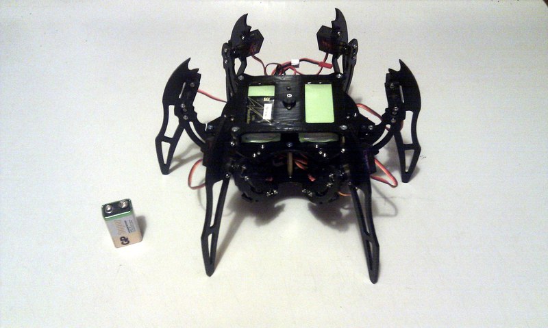
This battery was not only shorter in length, but also very narrow (the caliper showed a thickness of 17 mm). Given the maximum consumption of 5A at 6V, that is, 30 watts, I decided to put two batteries on the robot, which gave a total of 2.4AH at 11.1V, i.e. 26.64 Wh.
So, even with maximum consumption, the robot should live from them for 53 minutes.
Since the servos were so cheap, it was decided to change the design and make a robot with three servos on the leg. After that, in Google sketch, I figured out the design of the robot, and here's what happened: The

robot is surrounded by its parts.
As a result, I e-bay I ordered 20 MG90S servos, two batteries and a charger for them. The whole order cost me almost exactly 200 bucks. After that, I finally installed solid and a friend and I started real design.
At this stage, we shared responsibilities, a friend began to draw solid parts of his legs, and I started fixing the servos. Actually, this was one of the main components of the structure, which was the first joint of the leg and attached to the body, carrying out the rotation of the leg in the horizontal and vertical plane. It was necessary to move from the sketch depicted below to a real design.
The following problems occurred:
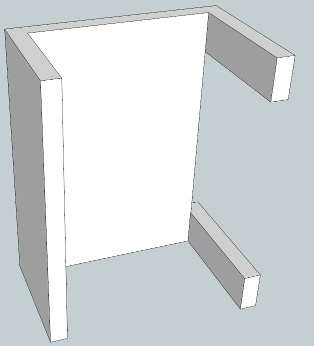
Proceeding from this, the first design of the holder for two servos resulted in a rather obvious solution, shown below:
The assembly consisted of two brackets screwed together, to which servos were screwed.
In the bracket intended for fastening the servo-drive, which rotates in the horizontal plane, a hole was made opposite its axis, into which it was supposed to insert a screw, which should serve as an extension of the axis.
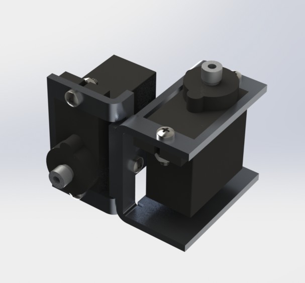
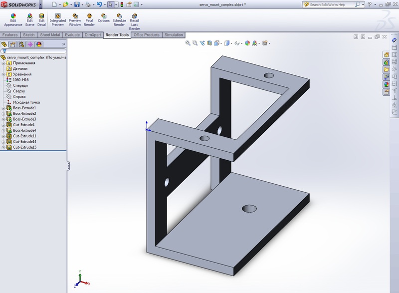
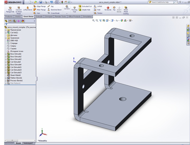
Both brackets were obtained from sheet aluminum by milling and subsequent flexible. Solid provides a very convenient utility that allows you to get a scan of a part without any effort, in a couple of clicks - to do this, just draw the part itself in the form in which you want to receive it:
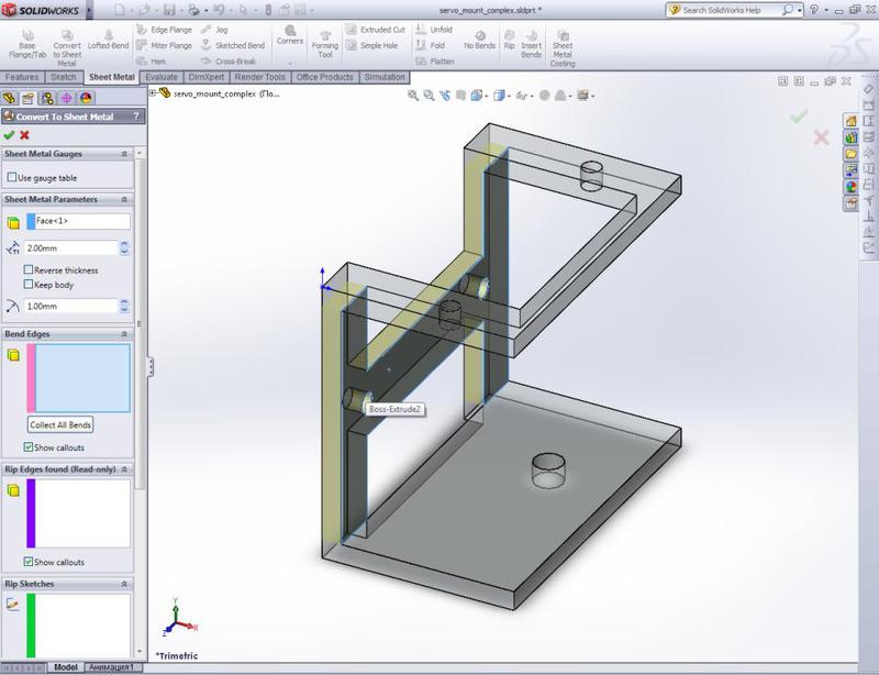
Then select Insert - Sheet Metal - Convert to sheet metal in the menu, specify the face that we will bend against, sheet thickness and bending radius:
After clicking OK, we get the final part, the difference is visible to the naked eye:
In the left-hand tree, in addition to the bending itself, another, inactive - Flat-Pattern appeared.
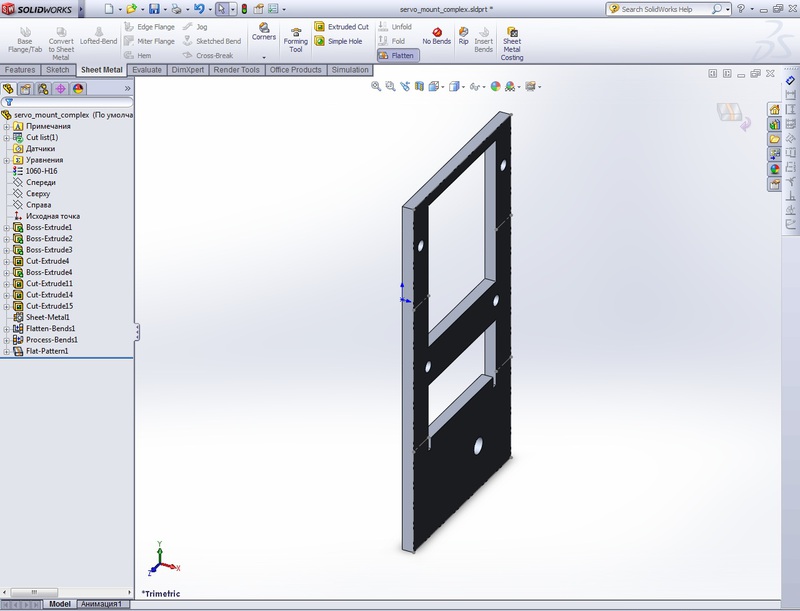
By activating it, we get the desired contour for milling: In this case, the solid cares even about the cuts in the part, adding them if necessary.
After the brackets for the drives, I sketched an approximate view of the body, and a friend threw off two parts of the leg.
The final render turned out like this:
This model finally made it possible to measure the mass of the robot. The results are as follows:
18 servos of 13.5 grams each = 243 grams, rounded to 250 g.
Two batteries of 75 grams = 150 g.
The structure (without cuts in the body) made of sheet aluminum 2 mm thick = 400 g.
Thus, the total weight of the robot was 800 gram. Based on this value and the limiting moment of the servo (2.2 kg * cm), as well as the long viewing of various videos on youtube dedicated to hexapods, the lengths of the legs were selected (the lengths that were used in the model shown above were taken only temporarily) .
As a result, it was decided to make the vertical part of the leg, “shin,” 110 mm, the horizontal, “thigh” - 60 mm, which gave a ratio close to 1: 2, which is usually observed in hexapods, and the moment is 6 * 0.8 = 4.8 kg * cm. One servo, of course, is not able to lift such a weight, but we have six legs, three of which constantly support the body, so the ultimate moment per servo can be assumed to be 4.8 / 3 = 1.6 kg * cm. In fact, since two drives are involved in the leg lift, the real moment is about half as much, i.e. about 600 g * cm. If desired, it was possible to calculate the exact values using the sapphire, supplementing the model with loads, but I decided to stay at the estimated value, since the drives promised to greatly exceed it.
The model revealed one drawback - the batteries prevented the rotation of the drives, if you place them inside the robot, so it was decided to transfer them to the roof.
In addition, I was worried about the design of the holders for servos - I did not want to order bending at all, and there was a wonderful prospect of spending the weekend with a vice, trying to bend a thick aluminum sheet with acceptable accuracy.
After sitting for a while, I redid the holders, and this design became the final one, made in a real robot:
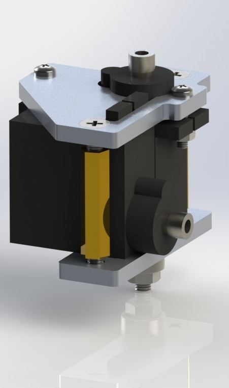
The assembly consists of two completely flat parts with slots for servo protrusions and is screwed using two standard racks. As before, a screw acts as an axis, which, however, had to be replaced with a screw with a hidden head. Otherwise, one of the drives would rest against the screw head.
The legs were also redrawn, firstly, the length of their parts was adjusted, and secondly, their shape was changed to a more decorative one, so as not to give the impression of spare parts from the children's designer:
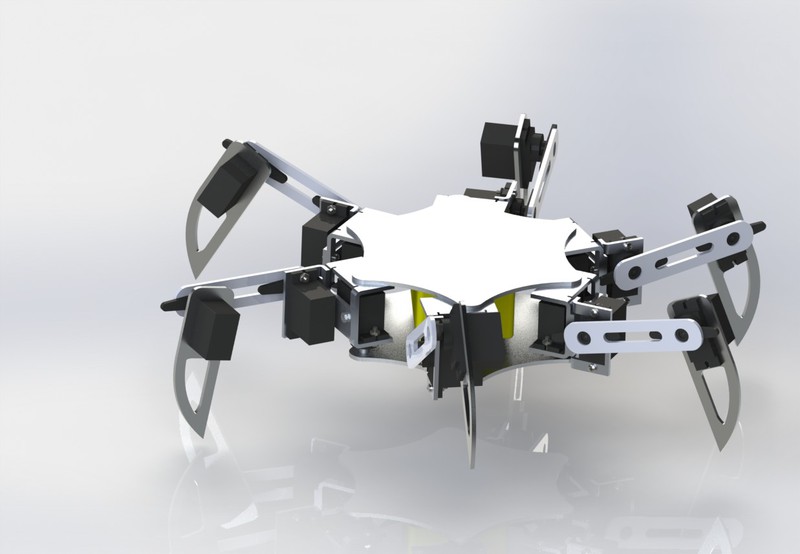
Finally, the result of all the work was the new robot model that I present Your attention:
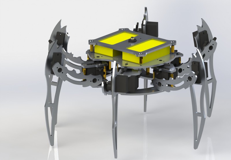
Then the robot received the name Ectognathus (from insecta ectognatha, one of the names of insects, also called hexapoda, six-legged), for which I thank another friend of mine.
After the model was completed, it was enough to drop Solidworks files to any office engaged in milling and get the desired details. And since all of them were flat in the final version, no additional operations were required and immediately after milling it was possible to screw the structure, having previously been purchased with screws, bearings, racks and nuts.
On this design ended and started ...
Since this article has already turned out to be quite voluminous, the details of the transition from the model to the real device and the associated problems and schools (of which there were quite a few!) Are described in the next article .
Thanks for attention!
So, meet - Ectognathus.
For quite some time I planned to assemble a robot. To be more precise, I chose between several options - I tracked off tracked and wheeled robots right away, because this is a pretty trivial decision, and the choice was mainly between a quadrocopter and a hexapod.
I was always attracted to micro quadrocopters, but what always upset me about them was that they flew for a very short time from the battery. Once I remembered that I had three micro-servos lying around, and in a day I assembled such a small robot:
It turned out, of course, clumsy and poorly controlled - because it had only three degrees of freedom for the whole body, but for some reason I really enjoyed managing it and writing software for it.
Remembering my desire to collect something larger, I finally abandoned the thought of a copter and decided to make a hexapod. I wrote about this to a friend, and he decided to join the project.
Development start
Initially, we planned to assemble a robot with two servers on the leg. This would reduce the price (12 servos versus 18!) And power consumption. In designs of this kind, one servo drive controls the rotation of the leg in the horizontal plane, the second - its lifting. The leg, as in the three-server version, consists of two parts, but they are connected by a frame, and not by an additional servo drive. Thus, in extreme positions, the leg can be either “raised and pressed to the body” or “lowered to the surface and set aside”, in contrast to the three-server version.
To begin with, I had to estimate the design of the leg, for which I decided to use Google SketchUp 3D. At this point, I didn’t have a single machine-builder installed on my computer, or even a single program for 3D modeling, so I decided to download a free, and, according to many, simple Google program. The final model was planned, of course, to do in SolidWorks.
Looking ahead, I will express my subjective opinion. Even for quick fixes of this kind, choose SolidWorks. After I switched to it, I realized that it is more convenient in any case. At least due to convenient bindings, model hierarchies, etc. Not to mention that you do not have to do double work and draw models from your 3D program into solid. The Google program has only three advantages - free, weight (30 meters) and a huge repository of models into which users upload their creations, so, for example, the servo was already there.
So, I started with a Google sketch and drew here such an approximate design:
After thinking, drawing and thinking again, it turned first into this:
and then into this:
All parts were designed for milling from aluminum, so they had to either have a flat shape or be obtained during bending. Of course, it was still just a sketch, and not the most successful version, but it was decided to pause on this and choose servos. The main criteria were the size of the drives and their speed. Basically, the e-bay presents standard servos and microservices. Standard servos have a healthy variation in parameters and prices, the most expensive I've seen is a 300 bucks servo unit, the moment of which was about 60 kg * cm.
Microserves mainly had a moment of 1-2 kg * cm and a speed of about 0.1. When I just started designing, I chose this onea servo drive, the speed of which was almost two times higher than that of other microservices, at the same moment. But after I requested the drawings, it turned out that it wasn’t even micro at all, but a cross between micro and standard, and in the end I chose the very same servos on which I made my first three-server robot, MG90S , which cost three times cheaper than the past.
Также, чтобы дважды не заказывать, я выбрал в том же магазине аккумуляторы для робота. Когда я замерил ток, потребляемый трехсервовым роботом, я, честно говоря, был удивлен. По моим прикидкам он должен был потреблять около 300 мА, в реальности же значение тока скакало от 500 до 700 мА, то есть хексапод с 18 приводами должен был бы потреблять в шесть раз больше, около 4.5А при 6В питания. Так как ток получился немаленький, я решил взять какой-нибудь литий-полимерный аккумулятор подходящего размера. К сожалению, почти все литий-полимерные аккумуляторы большой емкости были очень длинными (8-12 см!), из-за чего пришлось бы делать туловище робота больше, чем я рассчитывал, но, к счастью, среди них нашелся вот такой.
This battery was not only shorter in length, but also very narrow (the caliper showed a thickness of 17 mm). Given the maximum consumption of 5A at 6V, that is, 30 watts, I decided to put two batteries on the robot, which gave a total of 2.4AH at 11.1V, i.e. 26.64 Wh.
So, even with maximum consumption, the robot should live from them for 53 minutes.
Since the servos were so cheap, it was decided to change the design and make a robot with three servos on the leg. After that, in Google sketch, I figured out the design of the robot, and here's what happened: The
robot is surrounded by its parts.
As a result, I e-bay I ordered 20 MG90S servos, two batteries and a charger for them. The whole order cost me almost exactly 200 bucks. After that, I finally installed solid and a friend and I started real design.
Design
At this stage, we shared responsibilities, a friend began to draw solid parts of his legs, and I started fixing the servos. Actually, this was one of the main components of the structure, which was the first joint of the leg and attached to the body, carrying out the rotation of the leg in the horizontal and vertical plane. It was necessary to move from the sketch depicted below to a real design.
The following problems occurred:
- The MG90S, like most servos, has an axis on one side only. I would not want to fix them on one axis, as this can create unwanted deformations.
- Plastic "ears" for mounting servos are also located only on top, so one bracket could not do.
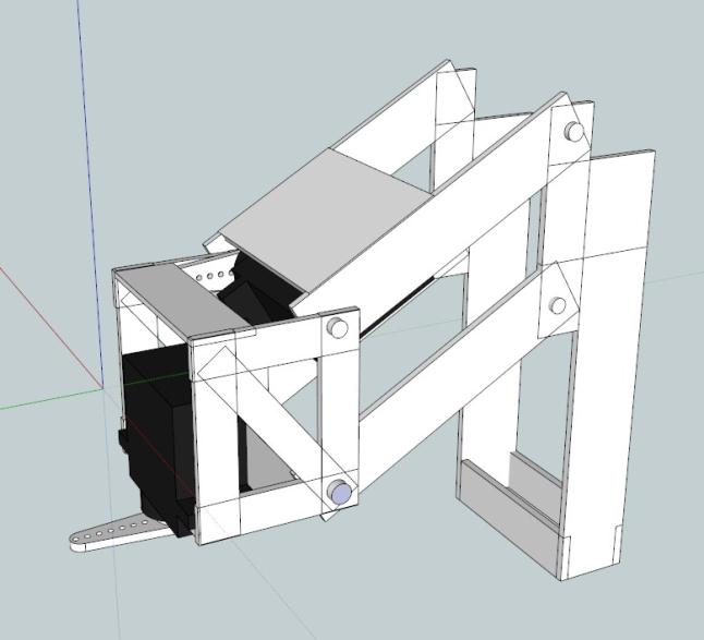
Proceeding from this, the first design of the holder for two servos resulted in a rather obvious solution, shown below:
The assembly consisted of two brackets screwed together, to which servos were screwed.
In the bracket intended for fastening the servo-drive, which rotates in the horizontal plane, a hole was made opposite its axis, into which it was supposed to insert a screw, which should serve as an extension of the axis.
Both brackets were obtained from sheet aluminum by milling and subsequent flexible. Solid provides a very convenient utility that allows you to get a scan of a part without any effort, in a couple of clicks - to do this, just draw the part itself in the form in which you want to receive it:
Then select Insert - Sheet Metal - Convert to sheet metal in the menu, specify the face that we will bend against, sheet thickness and bending radius:
After clicking OK, we get the final part, the difference is visible to the naked eye:
In the left-hand tree, in addition to the bending itself, another, inactive - Flat-Pattern appeared.
By activating it, we get the desired contour for milling: In this case, the solid cares even about the cuts in the part, adding them if necessary.
After the brackets for the drives, I sketched an approximate view of the body, and a friend threw off two parts of the leg.
The final render turned out like this:
This model finally made it possible to measure the mass of the robot. The results are as follows:
18 servos of 13.5 grams each = 243 grams, rounded to 250 g.
Two batteries of 75 grams = 150 g.
The structure (without cuts in the body) made of sheet aluminum 2 mm thick = 400 g.
Thus, the total weight of the robot was 800 gram. Based on this value and the limiting moment of the servo (2.2 kg * cm), as well as the long viewing of various videos on youtube dedicated to hexapods, the lengths of the legs were selected (the lengths that were used in the model shown above were taken only temporarily) .
As a result, it was decided to make the vertical part of the leg, “shin,” 110 mm, the horizontal, “thigh” - 60 mm, which gave a ratio close to 1: 2, which is usually observed in hexapods, and the moment is 6 * 0.8 = 4.8 kg * cm. One servo, of course, is not able to lift such a weight, but we have six legs, three of which constantly support the body, so the ultimate moment per servo can be assumed to be 4.8 / 3 = 1.6 kg * cm. In fact, since two drives are involved in the leg lift, the real moment is about half as much, i.e. about 600 g * cm. If desired, it was possible to calculate the exact values using the sapphire, supplementing the model with loads, but I decided to stay at the estimated value, since the drives promised to greatly exceed it.
The model revealed one drawback - the batteries prevented the rotation of the drives, if you place them inside the robot, so it was decided to transfer them to the roof.
In addition, I was worried about the design of the holders for servos - I did not want to order bending at all, and there was a wonderful prospect of spending the weekend with a vice, trying to bend a thick aluminum sheet with acceptable accuracy.
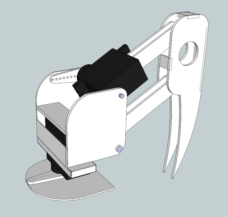
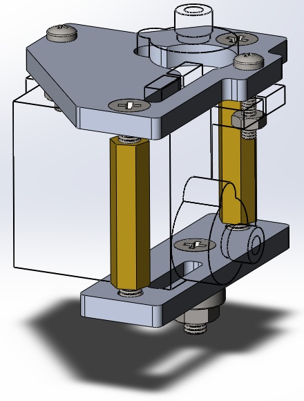
After sitting for a while, I redid the holders, and this design became the final one, made in a real robot:
The assembly consists of two completely flat parts with slots for servo protrusions and is screwed using two standard racks. As before, a screw acts as an axis, which, however, had to be replaced with a screw with a hidden head. Otherwise, one of the drives would rest against the screw head.
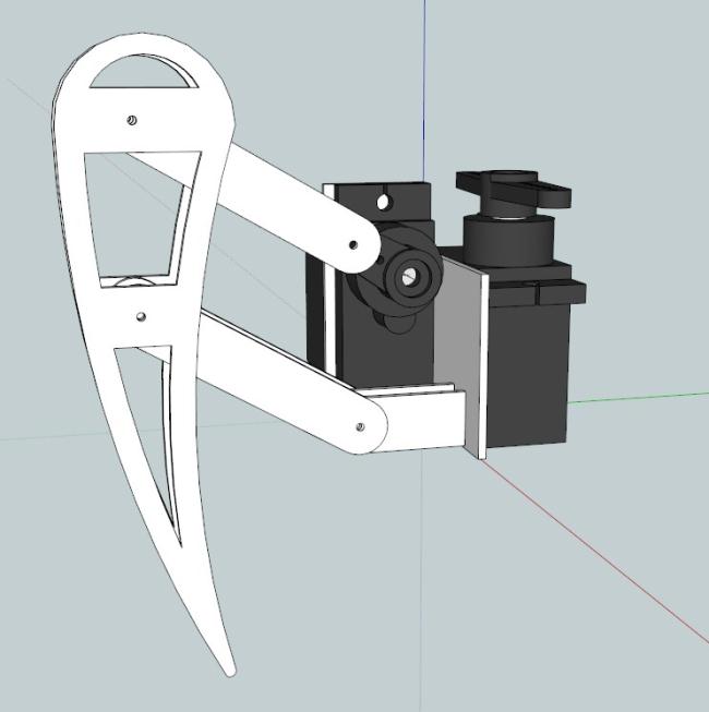
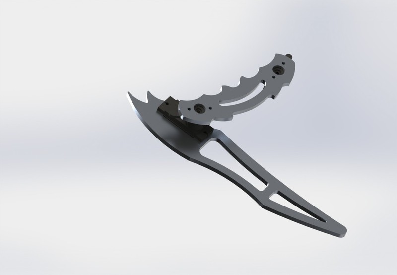
The legs were also redrawn, firstly, the length of their parts was adjusted, and secondly, their shape was changed to a more decorative one, so as not to give the impression of spare parts from the children's designer:
Finally, the result of all the work was the new robot model that I present Your attention:
Then the robot received the name Ectognathus (from insecta ectognatha, one of the names of insects, also called hexapoda, six-legged), for which I thank another friend of mine.
After the model was completed, it was enough to drop Solidworks files to any office engaged in milling and get the desired details. And since all of them were flat in the final version, no additional operations were required and immediately after milling it was possible to screw the structure, having previously been purchased with screws, bearings, racks and nuts.
On this design ended and started ...
Production
Since this article has already turned out to be quite voluminous, the details of the transition from the model to the real device and the associated problems and schools (of which there were quite a few!) Are described in the next article .
Thanks for attention!