June 24, 2012 at 14:35
About the MultiWii flight controller (copters, planes and helicopters)
ATTENTION, the article is outdated, but it can still be used for
 educational purposes. I suddenly wanted to tell more about the open and free project for controlling various aircraft (LA). In general, until recently, it was designed only for multi-rotor systems (copters), camera suspension stabilization, and in the beta version there was stabilization for the flying wing, but judging by the dev firmware, aircraft and helicopters will be officially added soon, and the stabilization of the flying wing flight has already been released from beta testing.
At the very beginning of the development of the project, there was a big problem with the sensors - they simply didn’t exist or were, but at incredibly high prices, so the first sensor for this flight controller was Wii Motion Plus (WMP) from the Nintendo Wii, and from here, in general, went the prefix Wii in the title. But time passed, the sensors became cheaper and now few people use the controllers from the console to create their MultiWii controller.
The main brain of the controller is the AVR processor, or rather, a simple Arduino board, to which various sensors cling to the I2C port. At the moment, to fly you will need any Arduino compatible board and gyroscope , for example ITG3205 sawn out (this is not slang, but I literally sawed out) from the Chinese WMP controller clone, but in such a configuration it will be quite difficult to control the copter, since aligning it parallel to the ground (and therefore eliminate the drift) will have to hands. And here the accelerometer comes to the rescue , which always knows where the "bottom", i.e. ground, and help keep the aircraft parallel to the ground. Thus, for a calm and stable flight, you need an Arduino and two three-axis sensors: a gyroscope and an accelerometer.
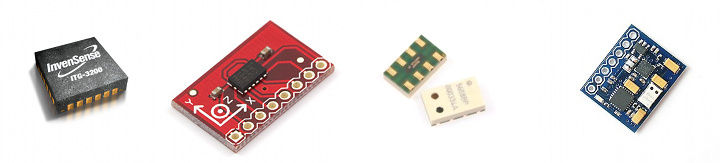
Additionally, you can add sensors such as a magnetometer, barometer and GPS receiver.
The magnetometer (aka compass) knows how the aircraft is rotated relative to the direction of the earth’s magnetic field and can help with heading hold, GPS navigation or in carefree mode for beginners when, regardless of the direction of the real nose of the device, the copter will fly from the pilot to the “forward” command "And to the pilot on the command" back ". The magnetometer is very negatively affected by magnetic fields from power supplies, wires, motors and everything that can produce electromagnetic waves, so when designing an aircraft frame, you should place this sensor as far as possible from all metal and magnetized.
Barometer(it’s also an atmospheric pressure sensor) can be useful for maintaining altitude, but keep in mind that altitude retention directly depends on the accuracy of the sensor, for example BMP085 (installed in many flight controllers) will give an accuracy of not more than + -1 meter, i.e. under the best conditions, your aircraft will fly in height within 1 meter or more. The more advanced MS5611 sensor can give an accuracy of up to 10cm. The barometer can be affected by any changes in pressure around, wind or air flow from the propellers, therefore it is recommended to put this sensor “under the hood” or stick a piece of foam rubber on it (like on microphones), but it is very important not to close the hole in the sensor (for example, filling glue there).
GPS receiveruseful and at the same time useless thing. On the one hand, it helps to include such good things as holding a position and returning to the starting point (returning home), and on the other, this very point is very approximate and depends on the accuracy of the receiver, the number of visible satellites or weather conditions, so it can turn out to hangnear the window of the female locker room in a circle with a diameter of about 3-10 meters (and with the addition of a good barometer in a flattened ball).
At the time of writing, there are attempts to add a sonar (ultrasonic rangefinder) and an optical displacement sensor (which are installed in the mice). SonarIt will allow to achieve a very accurate retention of height (about 1 cm) at a low height (up to about 3 meters), but it depends very much on the surface, for example, tall grass or mounds will cause interference and a sharp change in height, i.e. the copter will bounce or fall sharply. But the optical sensor can help the GPS receiver to more accurately hold the position.
The project boasts a large number of supported sensors for various purposes and with each release their number increases, and given the openness of the project, you can attach your own sensors.
Here is a list of them officially supported in MultiWii 2.0 firmware (and in brackets in the latest develop firmware):
As I wrote above, you can make your controller from the set of available sensors and Arduino, but it’s easier (and often more profitable) to buy a ready-made shawl that already has an AVR chip and a set of necessary sensors.
The most popular motherboard is Crius MultiWii, available in two versions Lite and Standart Edition, and a new version has recently appeared, differing only in the presence of a convenient I2C input and a smaller size.
Crius MultiWii Lite Edition has only 2 sensors on board: a gyroscope and an accelerometer. Standart Edition, in addition to the sensors available in Lite, boasts a BMP085 barometer and a compass. The new version of the board has an I2C connector for connecting a GPS module, which is a UART GPS receiver and an AVR chip (Arduino), which acts as an intermediary between the GPS and MultiWii controller (and in the foreseeable future it will completely take on GPS functionality to unload the main brain) .
In some online stores you can find other similar controllers, so if you come across something with 2 or 4 sensors and a 328p chip (or 1280/2560), then with a 99% probability it is a MultiWii controller.
I hope you already read my articles about copters and you know that the speed controllers and the receiver of the control panel are connected to the controller, and you can also attach the servos of the camera gimbal stabilization control.
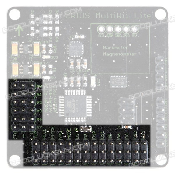
The picture shows the connectors for connecting the above devices. As you can see, each connector combines 3 contacts: S - signal, + - power (+ 5V) and G - ground. Also, the connectors have labels like A number and Ddigit - speed regulators, servos and sometimes additional channels of the radio control receiver are connected to them (correspond to the outputs on the Arduino). The inputs marked as THR, ROLL, PITCH, YAW, MODE are designed to connect the corresponding outputs of the receiver.
From each speed controller (ESC) there are 3 wires, one of which is + 5v (red or orange in the middle), but you need to supply power to the Crius board only from one of the ESC, and from the others you can (and even need) to power the remaining consumers: receiver and suspension servos. To do this, you need to remove the central wire from the connector for all (except one that will power the board) speed controllers and connect them to consumers or isolate.
To connect to other consumers, you can break off 2 contacts from the comb and solder them together:
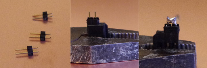
And then connect the power wire from the speed controller to the consumer power wire and tighten them into heat shrink: You
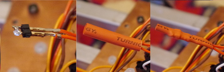
can do the same with unnecessary wires by folding the red wire in half and insulating it with heat shrink:
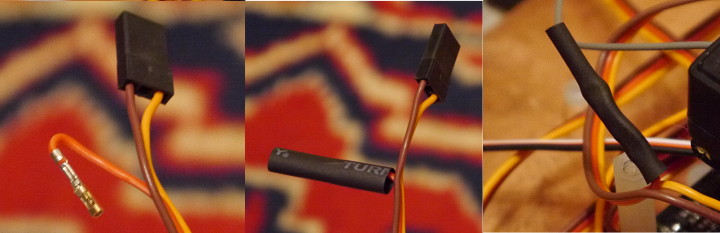
A set of wires comes with the controller - they must be used to connect the receiver, when it is enough to connect only the signal wires, one common contact (ground) and connect the power wire from one of the speed controllers.
First of all, it’s worth updating the firmware of the resulting controller, just download the firmware from the official MultiWii repository (please do not download the DEV version if you don’t know what it is and why), upload it to the Arduino IDE , configure the parameters of your flying machine and select a set of sensors in the config.h file, and then load the resulting sketch into the controller, selecting one of the boards with the 328p chip in the settings (but not the arduino UNO).
Since MultiWii 2.0, Crius controllers have appeared in the list of sensor sets:
Uncomment one of them that corresponds to your type of controller.
There are several, very common problems for beginners (relevant for version 2.0):
The graphical configurator is written in processing and is a cross-platform Java application, currently compiled for Linux, Windows and MacOS operating systems 32 and 64 bit architectures.
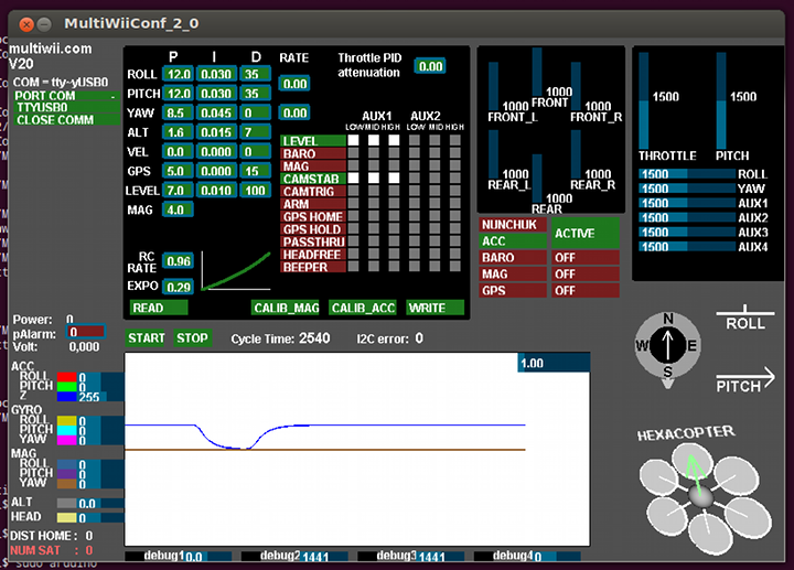
The appearance is a little scary, but often you do not have to climb here. Launch the configurator after inserting the flight controller into the computer. In the upper left corner, select the controller port and press the START button - the curves on the graph and the numbers next to it should run (ideally, everything should be smooth).
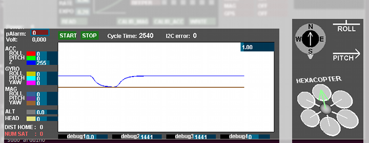
To the right of the graph is a three-dimensional model of your copter, as well as compass and tilt indicators. If the device is parallel to the horizon, and the PITCH and ROLL in the picture are tilted, press the CALIB_ACC button so that the controller remembers this position and always strives for it.
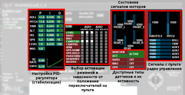
Above the graph are the settings of the PID controller, mode activation, and some status data. To see the values you need to press the READ button, to change them, click on the window with a number and move the mouse, and to save - press WRITE. Never change several PID values of the examiner at one time - otherwise you won’t understand what has become better or worse. You can read what and how to twist here .
A more detailed description can be found on the official website of the MultiWii project or on my website airm.ru , where I try to keep the same information in Russian, as well as many additions and news about the project.
All the described controllers can be easily found on ebay , aliexpress , goodluckbuy or rctimer. The
price can vary from 25 to 100 dollars, depending on the store and arrogance.
More than a year ago, I promised a flight on GPS, along the route and other navigation buns. So far, on MultiWii the controller managed to test the position retention.
In general, not bad, the copter swam in a circle with a radius of about 7 meters (did not set anything up before), but then suddenly it pulled somewhere far away from me and the tests were postponed.
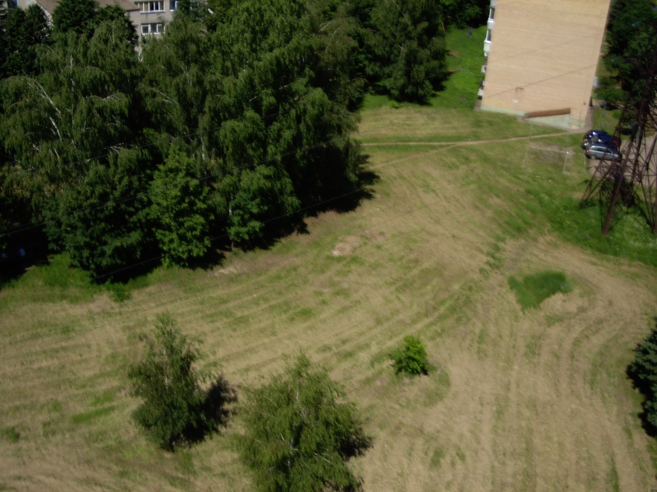
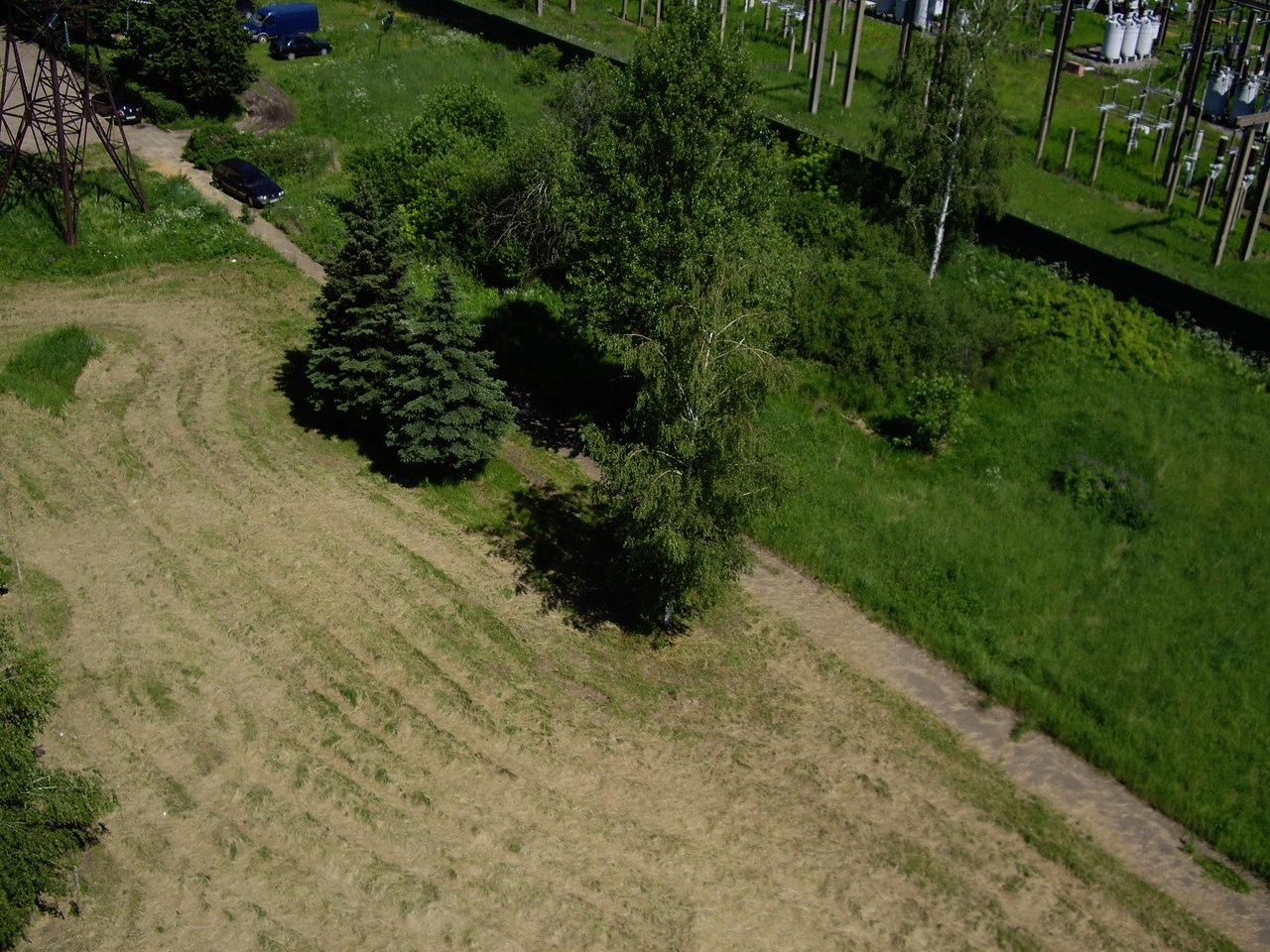
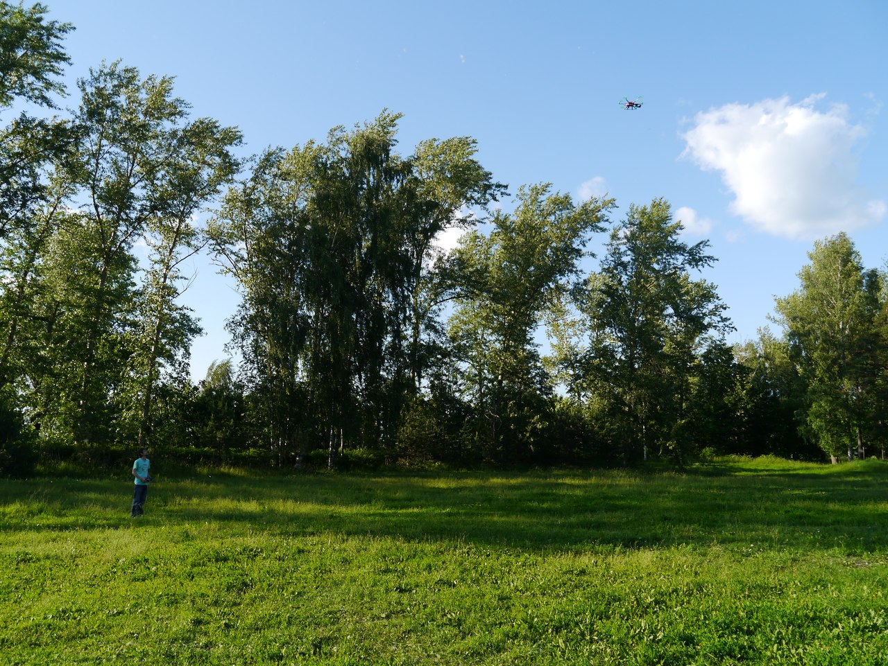
But then he began to gradually master the photo and video shooting from the air.
It turns out so-so, but another 2/3 of the summer ahead and a bunch of plans, including a separate remote for the operator.
Ask questions, if any, I will try to answer and supplement this article.
educational purposes. I suddenly wanted to tell more about the open and free project for controlling various aircraft (LA). In general, until recently, it was designed only for multi-rotor systems (copters), camera suspension stabilization, and in the beta version there was stabilization for the flying wing, but judging by the dev firmware, aircraft and helicopters will be officially added soon, and the stabilization of the flying wing flight has already been released from beta testing.A little background
At the very beginning of the development of the project, there was a big problem with the sensors - they simply didn’t exist or were, but at incredibly high prices, so the first sensor for this flight controller was Wii Motion Plus (WMP) from the Nintendo Wii, and from here, in general, went the prefix Wii in the title. But time passed, the sensors became cheaper and now few people use the controllers from the console to create their MultiWii controller.
Components
The main brain of the controller is the AVR processor, or rather, a simple Arduino board, to which various sensors cling to the I2C port. At the moment, to fly you will need any Arduino compatible board and gyroscope , for example ITG3205 sawn out (this is not slang, but I literally sawed out) from the Chinese WMP controller clone, but in such a configuration it will be quite difficult to control the copter, since aligning it parallel to the ground (and therefore eliminate the drift) will have to hands. And here the accelerometer comes to the rescue , which always knows where the "bottom", i.e. ground, and help keep the aircraft parallel to the ground. Thus, for a calm and stable flight, you need an Arduino and two three-axis sensors: a gyroscope and an accelerometer.
Additionally, you can add sensors such as a magnetometer, barometer and GPS receiver.
The magnetometer (aka compass) knows how the aircraft is rotated relative to the direction of the earth’s magnetic field and can help with heading hold, GPS navigation or in carefree mode for beginners when, regardless of the direction of the real nose of the device, the copter will fly from the pilot to the “forward” command "And to the pilot on the command" back ". The magnetometer is very negatively affected by magnetic fields from power supplies, wires, motors and everything that can produce electromagnetic waves, so when designing an aircraft frame, you should place this sensor as far as possible from all metal and magnetized.
Barometer(it’s also an atmospheric pressure sensor) can be useful for maintaining altitude, but keep in mind that altitude retention directly depends on the accuracy of the sensor, for example BMP085 (installed in many flight controllers) will give an accuracy of not more than + -1 meter, i.e. under the best conditions, your aircraft will fly in height within 1 meter or more. The more advanced MS5611 sensor can give an accuracy of up to 10cm. The barometer can be affected by any changes in pressure around, wind or air flow from the propellers, therefore it is recommended to put this sensor “under the hood” or stick a piece of foam rubber on it (like on microphones), but it is very important not to close the hole in the sensor (for example, filling glue there).
GPS receiveruseful and at the same time useless thing. On the one hand, it helps to include such good things as holding a position and returning to the starting point (returning home), and on the other, this very point is very approximate and depends on the accuracy of the receiver, the number of visible satellites or weather conditions, so it can turn out to hang
At the time of writing, there are attempts to add a sonar (ultrasonic rangefinder) and an optical displacement sensor (which are installed in the mice). SonarIt will allow to achieve a very accurate retention of height (about 1 cm) at a low height (up to about 3 meters), but it depends very much on the surface, for example, tall grass or mounds will cause interference and a sharp change in height, i.e. the copter will bounce or fall sharply. But the optical sensor can help the GPS receiver to more accurately hold the position.
The project boasts a large number of supported sensors for various purposes and with each release their number increases, and given the openness of the project, you can attach your own sensors.
Here is a list of them officially supported in MultiWii 2.0 firmware (and in brackets in the latest develop firmware):
| Gyroscopes | Accelerometers | Barometers | Magnetometers |
|---|---|---|---|
| WMP ITG3200 L3G4200D (MPU6050) | MMA745 ADXL345 BMA020 BMA180 NUNCHACK LIS3LV02 LSM303DLx_ACC | BMP085 MS561101BA | HMC5843 HMC5883 AK8975 MAG3110 |
Ready-made controller boards
As I wrote above, you can make your controller from the set of available sensors and Arduino, but it’s easier (and often more profitable) to buy a ready-made shawl that already has an AVR chip and a set of necessary sensors.
The most popular motherboard is Crius MultiWii, available in two versions Lite and Standart Edition, and a new version has recently appeared, differing only in the presence of a convenient I2C input and a smaller size.
Crius MultiWii Lite Edition has only 2 sensors on board: a gyroscope and an accelerometer. Standart Edition, in addition to the sensors available in Lite, boasts a BMP085 barometer and a compass. The new version of the board has an I2C connector for connecting a GPS module, which is a UART GPS receiver and an AVR chip (Arduino), which acts as an intermediary between the GPS and MultiWii controller (and in the foreseeable future it will completely take on GPS functionality to unload the main brain) .
In some online stores you can find other similar controllers, so if you come across something with 2 or 4 sensors and a 328p chip (or 1280/2560), then with a 99% probability it is a MultiWii controller.
Description of pins for Crius and connection nuances
I hope you already read my articles about copters and you know that the speed controllers and the receiver of the control panel are connected to the controller, and you can also attach the servos of the camera gimbal stabilization control.
The picture shows the connectors for connecting the above devices. As you can see, each connector combines 3 contacts: S - signal, + - power (+ 5V) and G - ground. Also, the connectors have labels like A number and Ddigit - speed regulators, servos and sometimes additional channels of the radio control receiver are connected to them (correspond to the outputs on the Arduino). The inputs marked as THR, ROLL, PITCH, YAW, MODE are designed to connect the corresponding outputs of the receiver.
From each speed controller (ESC) there are 3 wires, one of which is + 5v (red or orange in the middle), but you need to supply power to the Crius board only from one of the ESC, and from the others you can (and even need) to power the remaining consumers: receiver and suspension servos. To do this, you need to remove the central wire from the connector for all (except one that will power the board) speed controllers and connect them to consumers or isolate.
To connect to other consumers, you can break off 2 contacts from the comb and solder them together:
And then connect the power wire from the speed controller to the consumer power wire and tighten them into heat shrink: You
can do the same with unnecessary wires by folding the red wire in half and insulating it with heat shrink:
A set of wires comes with the controller - they must be used to connect the receiver, when it is enough to connect only the signal wires, one common contact (ground) and connect the power wire from one of the speed controllers.
Nuances of setting MultiWii
First of all, it’s worth updating the firmware of the resulting controller, just download the firmware from the official MultiWii repository (please do not download the DEV version if you don’t know what it is and why), upload it to the Arduino IDE , configure the parameters of your flying machine and select a set of sensors in the config.h file, and then load the resulting sketch into the controller, selecting one of the boards with the 328p chip in the settings (but not the arduino UNO).
Since MultiWii 2.0, Crius controllers have appeared in the list of sensor sets:
//#define CRIUS_LITE // Crius MultiWii Lite//#define CRIUS_SE // Crius MultiWii SEUncomment one of them that corresponds to your type of controller.
There are several, very common problems for beginners (relevant for version 2.0):
- For the hexocopter, the receiver does not work - in config.h it requires to uncomment the line #define A0_A1_PIN_HEX, and to use the additional RC channel, you can uncomment one of the lines #define RCAUXPIN8 or #define RCAUXPIN12 and connect the receiver channel to D8 or D12
- Not all motors work or do not work synchronously - you need to calibrate the speed controllers, for this you need to connect all the signal and all common (ground) contacts and connect them to the Throttle (CH3) channel of the receiver, as well as connect one of the power wires, and then calibrate the speed regulator according to the instructions for it, but usually it is necessary to set the throttle stick to the maximum position, apply power to the speed controllers (I hope the screws are not forgotten to remove? otherwise it will be very painful), and then lower the throttle to the lower (minimum) laying down
- The motors rotate in the wrong direction - you need to change any 2 contacts coming from the speed controller to the motor
- The motors do not activate - check the settings of the switchgear, for this in the MultiWii configurator check that the extreme positions of the knob correspond to the values 1000 and 2000, and to the central position - 1500, if this is not so, correct and then recalibrate the speed controllers
Graphical configurator
The graphical configurator is written in processing and is a cross-platform Java application, currently compiled for Linux, Windows and MacOS operating systems 32 and 64 bit architectures.
The appearance is a little scary, but often you do not have to climb here. Launch the configurator after inserting the flight controller into the computer. In the upper left corner, select the controller port and press the START button - the curves on the graph and the numbers next to it should run (ideally, everything should be smooth).
To the right of the graph is a three-dimensional model of your copter, as well as compass and tilt indicators. If the device is parallel to the horizon, and the PITCH and ROLL in the picture are tilted, press the CALIB_ACC button so that the controller remembers this position and always strives for it.
Above the graph are the settings of the PID controller, mode activation, and some status data. To see the values you need to press the READ button, to change them, click on the window with a number and move the mouse, and to save - press WRITE. Never change several PID values of the examiner at one time - otherwise you won’t understand what has become better or worse. You can read what and how to twist here .
A more detailed description can be found on the official website of the MultiWii project or on my website airm.ru , where I try to keep the same information in Russian, as well as many additions and news about the project.
What, where, how much?
All the described controllers can be easily found on ebay , aliexpress , goodluckbuy or rctimer. The
price can vary from 25 to 100 dollars, depending on the store and arrogance.
GPS Flight
More than a year ago, I promised a flight on GPS, along the route and other navigation buns. So far, on MultiWii the controller managed to test the position retention.
In general, not bad, the copter swam in a circle with a radius of about 7 meters (did not set anything up before), but then suddenly it pulled somewhere far away from me and the tests were postponed.
But then he began to gradually master the photo and video shooting from the air.
It turns out so-so, but another 2/3 of the summer ahead and a bunch of plans, including a separate remote for the operator.
 |  |  |  |
Ask questions, if any, I will try to answer and supplement this article.