Car Satellite Alarm on STM32F1
The theory of creating a home-made car satellite alarm with a web interface and eCall / ERA-GLONASS support based on STM32 microcontrollers as the basis of the Smart Car concept and its use in Smart Home systems. Implementation of an analogue of Volvo On Call technology and the Toyota Friends automotive social network.
I finally decided to write the continuation of the article “Satellite Speedometer on STM32F1 and FreeRTOS” .
Let us consider how to make a car satellite alarm with a web-based interface with your own hands - the main ideas, the element base, the technical details of implementation. I note right away that the cost is at the level of one and a half thousand rubles (in the basic version), while industrial analogues (together with the installation) go in the region of 30-50 thousand rubles. There is no subscription fee - there are only expenses for mobile communication (about 100 rubles per month. With a competent approach to minimizing the transmitted traffic, ~ 60 rubles, or even less) will go per month. Thanks to the support of Glonass, an additional advantage appears in connection with the expected 100% equipment of the Russian fleet with Glonass systems. And at the same time, the described device carries innovative capabilities that are not yet on the market.
The device described below is universal - with the same success it can be installed and work both on the Zhiguli and on Lexus - both on mobile objects (cars, trucks) and stationary (houses, cottages, etc. ) Performs 3 main functions:
*Information - an analogue of Volvo On Call technology. Being at a considerable distance, you stay in touch with your car, if you have any device with Internet access (computer, netbook, iPhone, iPad, Android device, etc.) - find the location of your car, start the engine remotely, get information about its technical condition, etc. Management and monitoring of the machine is carried out through SMS / voice calls (dtmf) / site. The site is an Internet portal to which objects equipped with this device automatically “dump” information about their current state and take settings for their work from it. It is also an automotive social network (similar to Toyota Friends) for the interaction of objects (cars, houses) and people.
* Security - includes:
a) label with a 2.4GHz dialogue code based on STM32W, for automatic access to the object.
b) protection against jamming of the gsm signal (constant monitoring of the communication channel by the server + detection of the fact of jamming from the side of the alarm itself)
c) function of gsm / gps / glonass tracker - if the car is stolen or put into a parking lot, you can find out its current location.
d) hidden video surveillance - via rs485, video cameras consisting of STM32F4 and cmos cameras on board are connected with the alarm system.
d) digital relays - even by physically removing or disabling the alarm, the attacker will not achieve anything - the relays will de-energize vital circuits, and they can no longer be activated, even by directly supplying power to them. Also, digital relays control the pins in the doors - even if an attacker breaks the glass and / or breaks the lock cylinder - he won’t be able to open the door, even after breaking its lock - the electronic pins in the doors, which can only be unlocked by an alarm, will open the door.
e) as additional equipment, 1 or several gsm / gps / glonass beacons, also home-made, are used. Because for the reasons described below, the use of signaling alone is not enough. It is also recommended to use a hood lock, a steering lock (for example, a Guarantor), an armor film for glass (breaking glass to steal your things from the passenger compartment or penetrate inside will be extremely problematic - it protects even from air gun bullets)
*Rescue - a car equipped with this device will be able to independently call emergency services, even if the driver and his passengers are no longer able to take any action. To implement this feature, the device has support for eCall / ERA-Glonass technology. The installation of such devices is predicted to be able to save 2,500 lives a year in Europe annually, 4,000 lives a year in Russia and reduce the effects of injuries in road accidents by 14%.
* Logistics - for companies engaged in cargo transportation. Monitoring and tracking the movement of vehicles, accounting for fuel consumption in the fleet, etc.
To more clearly show what will be discussed, I’ll give a video from the industrial version of this device (which, incidentally, has fewer features at a significantly higher price):
And now - how to independently implement all this, ideas in general terms. In the end, consider the implementation on STM32 microcontrollers.
1. The general structure of the system.

- as I wrote earlier, the device is suitable for use not only in mobile objects (cars, trucks, etc. - “Smart Car”), but also in stationary (apartments, houses, cottages - “Smart House”). In general, automobile satellite alarms, as practice shows, are a good replacement for Smart Home systems for the automation and protection of apartments, cottages and other real estate. Of course, they cannot compete with such Smart Home systems as LonWorks, Legrand and Bticino, but they can quite solve the tasks that are of priority for the consumer when automating their home - security, remote monitoring and control, video surveillance, etc. Not always a consumer is ready to pay for automation the money that systems like LonWorks cost — he needs a budget solution, which can be a car satellite alarm. As an illustrative example, you can cite the resourcehttp://home-online.ru/solutions.html
In the case of Smart Car, the device is housed in a metal case that can withstand loads of up to 40G, which houses the alarm itself and a backup battery. This is a requirement of the ERA-Glonass standard - in the event of an accident and subsequent possible fire, the device must be able to contact emergency services and transmit the coordinates of the car, even if the driver and his passengers are no longer able to take any action on their part. In addition, a SIM chip is used instead of a SIM card (for more details, see the “SIM900 GSM module” section below).
In the case of “Smart Home” application, the device is placed in a conventional compact plastic case with a battery for placement in a place hidden to the attacker, while its power unit is placed in the case for mounting the electrical cabinet of the property on a DIN rail:

Now, consider the structure of the device itself, in case of automobile application:
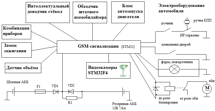
To collect data on the state of the car (engine speed, oil and liquid pressure sensors, etc.), a connection to the vehicle’s diagnostic connector is used using CA N / LIN. In the event that our device does not support this brand of car, a connection is used directly to the sensors and actuators of the car - tachometer / generator, nozzles, oil pressure sensors, coolant level, etc.
You can do without the immobilizer crawler, if the immobilizer supports remote start - this is set in its settings. Otherwise, you will most likely have to sacrifice one of the tags and apply the crawler.
My alarm is configured via USB - I use the USB CDC class in STM32, so on the computer side the device is defined as a regular com port, and you can work with it through any terminal (I use Putty).
Volume sensor - a standard external sensor is used, and you can use an accelerometer in the device itself, for example, LIS203DL (the plus is that this accelerometer is installed on the stm32f4-discovery debug board and there are well-documented examples of working with it).
To implement the autostart function in the case of manual transmission, we must be sure that the machine is not in gear. To do this, the user must either leave the car and arm it without turning off the engine (arming with the engine running), or install reed switches on the gearbox (the implementation is described here )
Cameras on the STM32F4 The
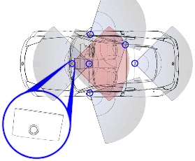
elemental base of the cameras is represented by the STM32F407 microcontroller + CMOS camera + external memory. They are connected to the main signaling unit via the RS-485 interface (at the physical level, and ModBus is used at the application level ). The best option is to place the cameras as follows:
Cameras work in photography mode. The STM32F4 microcontroller was not chosen randomly - it has a built-in synchronous parallel DCMI camera interface, which allows connecting cmos-cameras up to 1 megapixel. Among others, it has a Snapshot mode, which is used. Using the direct memory access (DMA) mechanism, data from the camera is immediately placed in an array in external memory connected via the FSMC interface of the microcontroller - while the computing resources of the kernel are not used.
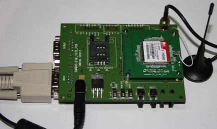
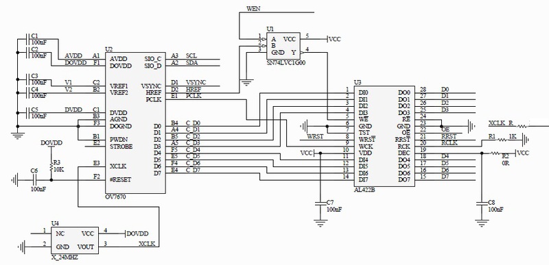
By the way, the use of a cmos camera with conventional microcontrollers is complicated by the fact that the same OV7670 camera does not know how to transmit data with a frequency of less than 10 MHz + the data from it needs to be placed somewhere. Therefore, to use cameras with conventional microcontrollers (as well as FPGAs), FIFO buffers are often used, for example AL422B, the memory capacity of which is enough to store 1 frame of the image from the camera: The device of the main signaling unit The main components of the main unit are the microcontroller stm32f103, gps / glonass module , gsm module SIM900. GPS / Glonass module At the moment I use the well-known gps EB500, but it is planned to switch to the GPS / Glonass module Geos-3M

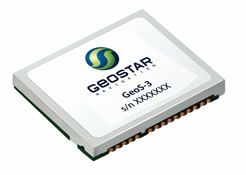
. If we compare it with the ML8088s / GL8088s, nv-08-c, then it compares favorably with the energy consumption from the first (judging by the engineering samples), and from the second with the price ($ 28 retail, $ 15 wholesale). By the way, it is planned to use GPS / Glonass-module Geos-1M in ё-mobiles.
Using a dual GPS / Glonass module instead of ordinary GPS gives us two main advantages:
1) Using the GPS + Glonass mode allows you to increase the accuracy and success of determining coordinates (because we have more satellites available - not only GPS, but also Glonass).
2) The commercialization of Glonass technology is gaining momentum. Already at the legislative level, the installation of Glonass terminals is required for installation on a number of vehicles. Therefore, the support of Glonass in an automobile device is an additional competitive advantage that ensures its attractiveness in the market.
Working with the module does not cause problems - the module takes care of all the mathematical processing, outputting text strings with ready data (NMEA protocol). About how to organize their analysis and work with the module on the STM32 microcontroller, I wrote in a previous article, “Satellite Speedometer on STM32F1 and FreeRTOS” . By the way, the Geos-3M module supports data output in binary form.
When using such modules, the main problem is the increased noise level in the parking lot, which is expressed in the drift of coordinates and speed on a stationary object. And overnight the car, if you do not take additional measures, can wind up more than one circle on the map, while remaining in reality motionless all the time. The best solution to this problem without the use of additional components that I know of is the control of azimuth changes with the simultaneous calculation of coordinates (not to take into account with a small change) - with this approach, we do not take into account garbage, and we get memory and traffic savings.
In any case, any kind of mathematical processing of GPS / Glonass module readings is not ideal - even in the best case, it turns out that we do not take into account the low speed and a small change in coordinates. The use of a 3-axis gyroscope and an automobile speedometer can jointly solve this problem in the case of automotive applications. It can be combined with the Glonass / GPS module. As such a gyroscope, you can take, for example, the L3G4200D ($ 19). For automotive applications, the A3G4250D gyroscope has already been announced, but it is not yet available for sale. Such a gyroscope works on the I2C / SPI bus:

So, how does the gyroscope and speedometer help us?
a) we get the opportunity to quite easily defeat the drift in the parking lot - discard false data on the speed and change of coordinates in the parking lot with GPS / Glonass
b) If GPS / Glonass signals disappear, we get the opportunity to continue to conduct geographical positioning by speedometer and gyroscope - continue to track.
In the parking mode, when the car is stationary, the GPS / Glonass module tells us that we are moving at a low speed, the coordinates are drifting. But we get zeros from the gyroscope, which gives us reason to believe that we are standing still and the readings of the module can be ignored. If the GPS / Glonass signal disappears in motion, we take speed information from the speedometer, and turn information (angular speeds) from the gyroscope.
In terms of implementation, it’s essentially not important for us which speed sensor is used and where to get it from in the car. Almost everywhere, the amplitude of the speed signal is 12 volts, the difference is only in the number of pulses per second. Here you can simply enter the self-calibration - in the GPS / Glonass movement, automatically determine how many pulses per 1 meter of the path, and memorize the resulting constant.
It is also necessary to enter the temperature calibration of the gyroscope by GPS / Glonass, as its side is temperature drift.
It should be noted here that calculating the path according to the gyroscope and speedometer by the Cortex M3 is a very dubious task. The data must be sent to the server, on which the calculation will already be made. But in case we are ready to abandon Glonass, leaving only GPS, you can look at the LEA-6R GPS modules - it has a DR (dead reconing) function that allows you to connect directly to the module additional channels for receiving path information - a gyroscope and speedometer. Accordingly, both the microcontroller and the server are unloaded in this case in terms of calculating coordinates - the module itself is already engaged in this, providing ready-made NMEA data. Which significantly reduces the time and laboriousness of developing a finished device. It is a pity, but such decisions supporting Glonass are not yet visible on the horizon .: - (
And now - it's time to consider working with a GSM modem.
GSM / GPRS module SIM900
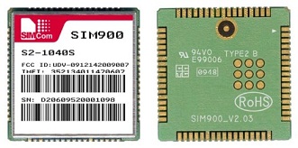
Earlier, in embedded systems, the use of the sim300 gsm module was common, but soon he was replaced by sim900 ($ 21), and after a while, his lightweight budget version sim900r began to be released (unlike sim900, this is a dual-band module with reduced program memory and with restrictions on use in countries - only in Russia and border countries). SIM900 is a quad-band (850/900/1800/1900) GSM / GPRS module with an integrated TCP / IP stack. Allows you to send MMS messages, has built-in support for the application layer protocols HTTP, FTP, and in the latest firmware - DTMF decoding, the ability to detect jamming of a GSM signal (Jamming Detection) and support for eCall / ERA-GLONASS rescue systems (the latter will be described in more detail below ) You can control the modem using AT commands,
Raising a board for this module for debugging on your own is a thankless task, especially since the debugging board for this module is quite inexpensive - $ 65, so I recommend taking it:
To support Era-Glonass, DTMF decoding, etc. you need to update the firmware - to do this, contact the distributor in your region (I contacted MT-System), and then flash it through the debug port.
It is more convenient to debug work with the module from a computer. Fortunately, I initially laid down USB support for the device in the device for setting the settings, then I did this: I connected the library from ST to implement the USB CDC class, which made it possible to communicate with the device through any terminal that works with a serial port (the device is seen in the system as a virtual com- port). The device sends commands to the SIM900 module, while the module includes echo retry - i.e. everything that is sent to him, he sends back, along with the answer. And the microcontroller sends the entire response from UART from SIM900 to USB to my terminal box. Those. in the process of interaction between the device and SIM900, the whole process of communication is clearly visible on the screen + from the terminal it becomes possible to control the process of communication by setting unique breakpoints.
Getting started with the SIM900 module is described here and here , so I ’ll focus on the most interesting points:
SIM900: GPRS
By default, the device sends data (current coordinates, vehicle speed, etc.) to the web server and receives settings from it. Let's look at a simple example of how you can send data via HTTP to your server (the operator in our case is MTS): SIM900: Protection against jamming a GSM signal An attacker can safely disrupt the connection of our device with the server via a GSM channel, and for this It has 3 ways: 1) GSM jamming

- Using such a simple device costing $ 119, you can drown 3G / GSM / CDMA modems in a radius of 5-20 meters. And the disturbing communication channel of satellite gsm signaling with the server will be broken.
2) Substitution of the base station of a cellular operator
There are devices that fit in a briefcase and allow you to impersonate a base station of a cellular network: the
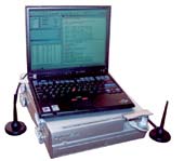
device’s GSM modem will not be able to distinguish a real base station from a fake mobile one, and in case of an alarm it will not be able to send data via an alarm channel.
3) Cloning a SIM card.
- the number used by the gsm alarm system has a second SIM card, which is in the hands of the attackers. And if you silence the alarm signal with the jammer from item 1, then the device with this number (from the attacker) will be available and will not give alarms. If the alarm check is based on periodic dialing, then the dialing will be carried out on a fake SIM card, and it will not cause an alarm.
4) Field detector for detecting radio transmitters (including GSM devices)
- used to localize the installed alarm. You can buy such a miracle device for $ 43:
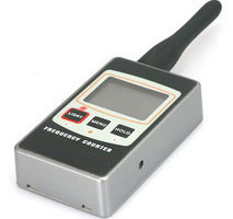
- allows you to identify radio transmitters emitting in the range of 1 MHz-2.6 GHz. The screen displays the frequency of the device and the signal level, which allows you to find the installation location of the alarm and neutralize it.
In order to protect against item 4, a car is installed in addition to the standard alarm gps / gsm-beacons, which will be discussed in the section “SIM900: Using user applications. GPS / Glonass - beacons. ".
To protect against items 1 and 3, the SIM900 module supports the Jamming Detection function, which is designed to detect attempts to jam the signal - the AT + SJDR command is used for this. If the modem is jammed, the message “+ SJDR: JAMMING DETECTED” will be displayed. Of course, the modem will not have time to contact the server and transmit alarm data. But the device will be able to turn on the siren, block the car and remember that it was jammed - after the resumption of communication, this information will go to the server.
To protect against all of the above points in modern satellite gsm alarms, GSM channel control is used. The bottom line is that the gsm modem communicates with the server with a given frequency - for example, sends data via HTTP. If within the last N minutes the modem has not contacted the server - this is an occasion to raise an alarm and call / send SMS from the server to the owner of the machine. Of course, this is not a panacea for 100% of cases - somewhere just a bad reception of a GSM signal. In other cases, an attacker can affect the human psyche - periodically dimming the signal and forcing the owner of the car to run out to his car. After some time, the owner will get tired of it and he will turn off the control of the communication channel, thereby giving the hijacker a green light. Nevertheless, the control of the communication channel is a tangible help in solving the problem of protection against theft.
SIM900: Receiving coordinates in the absence of GPS / Glonass signals
About the current location of the car, we get the coordinates from GPS / Glonass satellites. But a situation may arise in which obtaining these coordinates is impossible (for example, there is no signal). In this case, the option of calculating the coordinates through a bunch of speedometer + gyroscope I have already considered above. But there is another solution - the base stations of the mobile operator may come to our aid, one of which we are connected to. From base stations we can receive information such as LAC and CELLID (area code and base station identifier, respectively). This information uniquely identifies this base station, among others, the current mobile operator. And the coordinates of the base stations are widely known. Therefore, knowing which base station the modem is connected to, you can determine the geographical coordinates (longitude and width) of this station, and thereby the approximate coordinates of the modem itself. The geographic coordinates of the lac and cellid base stations can be obtained through the Yandex API, Google, opencellid.org, location-api.com. By the way, mobile operators do not publish the coordinates of their base stations in the public domain. Therefore, the same Yandex receives this information from its users who have downloaded Yandex applications and have a GPS receiver in their phone. The Yandex application receives the cellid and lac of the base station from the gsm modem of the phone, and the current geographic coordinates from the gps receiver and sends it to the Yandex server - this way the lists of geographic coordinates of the base stations Beeline, MTS and Megafon are replenished. Google, opencellid.org, location-api.com. By the way, mobile operators do not publish the coordinates of their base stations in the public domain. Therefore, the same Yandex receives this information from its users who have downloaded Yandex applications and have a GPS receiver in their phone. The Yandex application receives the cellid and lac of the base station from the gsm modem of the phone, and the current geographic coordinates from the gps receiver and sends it to the Yandex server - this way the lists of geographic coordinates of the base stations Beeline, MTS and Megafon are replenished. Google, opencellid.org, location-api.com. By the way, mobile operators do not publish the coordinates of their base stations in the public domain. Therefore, the same Yandex receives this information from its users who have downloaded Yandex applications and have a GPS receiver in their phone. The Yandex application receives the cellid and lac of the base station from the gsm modem of the phone, and the current geographic coordinates from the gps receiver and sends it to the Yandex server - this way the lists of geographic coordinates of the base stations Beeline, MTS and Megafon are replenished.
So, we want to determine our coordinates by GSM. To do this, the SIM900 module needs to issue the AT + CREG = 2 command - it will give a response in + CREG format:,,. We will also receive this answer automatically when the modem changes the current base station. Then we transfer these via GPRS to our server. Based on this data, the server takes geographical coordinates from its cache, and if it is not in the cache, it makes a request for one of the services for determining the coordinates of base stations - for example, Yandex, and we get the coordinates in the format. More details on the use of these services can be found at http://www.xakep.ru/post/48378/
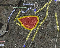
As a result, we issue a map with a shaded area to the user on the site, which shows the approximate location of the car based on gsm coordinates.
AT + CIPGSMLOC command appeared in SIM900 modems not so long ago, which immediately gives out immediately the geographical coordinates of the gsm network. But it does not carry anything fundamentally new in itself - this team does everything that I wrote above. Receives lac, ci, sends them to Google and returns the result.
At the same time, I note that some modems have the ability to sequentially connect to all in the BS in the field of visibility. This can be used to clarify the gsm coordinates - in this case, we can find out lac, ci of all the nearest BS, find out the geographical coordinates from them - they will be the vertices of the polygon in which our module is located:
SIM900: Using custom applications. GPS / Glonass - beacons.
Car satellite alarms are, of course, good. But they can find and deactivate it. For example, using the field detector discussed above. Gps / gsm beacons come to the rescue, which are miniature devices with a GPS (or GPS / Glonass) receiver, GSM modem and battery. Such beacons are difficult to detect visually, because they hide well in the hidden places of the car. It’s difficult to detect them with a field detector. most of the time such a lighthouse simply sleeps, only occasionally waking up to register on the network, transfer its coordinates to the server, and fall asleep again.
The question may arise - what about the microcontroller? The answer is that it is not needed. Modern GSM modems have a special memory area for launching user applications. For example, Sierra Wireless modems use the OpenAT operating system, in which your programs can run. And SIM900 supports Embedded AT technology - you simply create your program in the SIM900DevIDE environment, download it with firmware to the modem - and enjoy life. There is no need to spend money on a separate controller - the modem will take the data from the GPS / Glonass receiver itself and send it to your server. Along with the SIM900DevIDE environment, there are already examples of programs, so you won’t have to write your application from scratch.
SIM900: eCall / ERA-GLONASS Rescue Systems.
ERA-Glonass is a system designed to reduce mortality and injuries on Russian roads, based on the use of Glonass. If a person gets into an accident - a car equipped with a terminal of this system is capable of calling emergency services independently without human intervention. There is also a manual ability to call them by pressing the SOS button (something similar is in Volvo On Call and Lexus Link, but there it is paid services + the cost of the equipment itself is quite high). In order for cars coming from the EU countries to us to be able to receive emergency assistance in Russia, and vice versa, so that our car equipped with the ERA-GLONASS terminal can work with Western infrastructure when traveling abroad, there is full compatibility with the European system eCall. Those. if we have the support of ERA-GLONASS, then being abroad in the EU countries, we will be able to use the eCall emergency response system. According to preliminary forecasts, the use of ERA-Glonass / eCall system terminals will save 2,500 lives in Europe annually, 4,000 lives in Russia, and reduce the consequences of accidents by about 14%. So far, there is only testing and deployment of ERA-Glonass and eCall systems. The final commissioning of eCall is scheduled for 2014, and ERA-Glonass - at the end of 2013 (we are optimistic, however!). Since 2013, all cars produced from the assembly line should already have the support of ERA-GLONASS. But more than a dozen years will pass before most of our population will have cars with an already built-in ERA-GLONASS / eCall terminal,
The ERA-GLONASS terminal is not difficult to make by yourself - for this, modems have already appeared that support the technology of transmitting data via the voice channel - the in-band modem function. Let's see how it works:
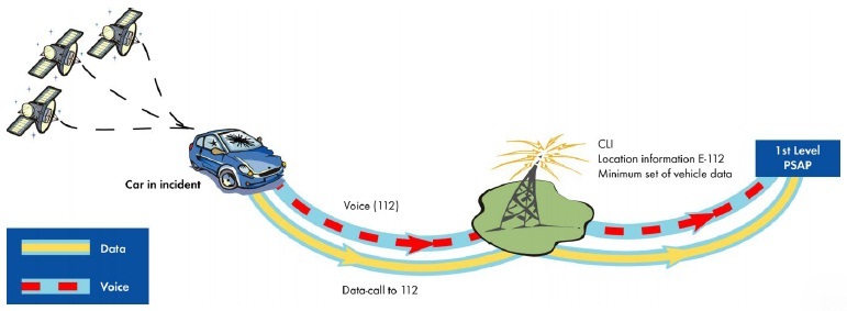
But first, answer the question - why not just use regular GPRS, SMS? The fact is that they introduce a significant delay in the transmission of data. In in-band modem data is transmitted instantly, such a call will be allocated the highest priority by the mobile operator, even in the event of a network congestion. If the network is congested, then active calls of other subscribers will be disconnected so that your terminal can contact 112 service.
In the event of an accident (determined by the readings of the car’s sensors), or if you press the SOS button yourself, we make an emergency call to 112 and send it to the PSAP server (in Russia, to the PSAP server of the federal operator NIS-GLONASS, which supports version 3GPP 8.6 .0 / 9.4.0. PSAP stands for Public Service Answering Point) An MSD message (MSD-Minimum Set of Data, with a limit of 140 bytes, which contains the following information:
1) Control data: is the call test, is it possible to trust the indicated geo-coordinates, type of vehicles (passenger car ample (class M1), city / intercity bus (M2-M3), light commercial vehicle (N1), truck (N2, N3) motorcycle - classes L1e-L7e)
2) Vehicle identification data: VIN-number of your car
3) Vehicle propulsion storage type: what your car drives (gas, diesel, gasoline, hydrogen, electric motor) - you can specify several values at the same time (if, for example, the car uses both gas and electric energy to move)
4) Time stamp: Indicate the current date, including seconds
5) Current location of vehicle: indicate the geographic longitude and width obtained from our GPS / Glonass module. If you don’t know, you can simply leave the field blank.
6) Direction of vehicle: the direction of movement of the machine along the magnetometer built into the terminal, in degrees, with 0 being magnetic north. The countdown is clockwise, in steps of 2 degrees. Those. if the deviation is 120 degrees from magnetic north, then we indicate the value 60 in MSD. Or just 0xFF if the direction of movement is not known.
7) Location delta with respect to vehicle Location, Location delta with respect to recentVehicleLocationN1: The difference in geographical coordinates between the current coordinates and those coordinates that were recorded at the time of the accident. These fields are also optional.
8) Number of passengers: the minimum known number of passengers. If we don’t know, specify 0xFF. It is automatically calculated as follows: in the car’s seat belts there are sensors that fix whether the seat belt is latched (for us this means that the passenger has taken the appropriate place) - the number of activated sensors and write in this field.
9) Optional additional data: any additional information (binary / bcd / xml / asn.1 / ascii), the format is not strictly regulated.
10) CRC32 - CRC32 checksum of our MSD message.
The total length of the MSD cannot exceed 140 bytes. The default connection is initiated by the client (i.e. us), but it can also be initiated by the service 112 PSAP server.
One of the first modems that implemented in-band modem for working with eCall / ERA-GLONASS was the Sierra Wireless company SL6087 modem. But a couple of months ago, such support appeared in the firmware for the SIMCom SIM900 modems used by me. Moreover, it is possible not only to send a ready-made MSD message: but also to transfer this function to the modem itself, indicating the values of the MSD message fields through AT commands: The operator of the ERA-GLONASS service will display this information as follows: For testing it’s not at all necessary to contact NIS-Glonass - you can organize a test PSAP server on your side with an OpenAT modem, you can read more here

A device that implements this functionality is placed in a metal case that can withstand a load of 40G (after all, the device should function in the event of an accident) and has a built-in battery for autonomous operation.
Also, additional requirements apply to the SIM card - using a regular SIM card is not acceptable here, because in the event of an accident, the mechanical contact of the SIM card with the device can most likely be broken. Here their analogues come for use in embedded devices - SIM chips, which have two main advantages compared to SIM cards:
1) The best contact due to the lack of mechanical connections - the SIM chip is soldered to the board and not inserted mechanically into the holder,
2) An extended temperature range (-40 ... +105 degrees Celsius), as well as increased resistance to dust, selection, humidity, shock, corrosion, chemically aggressive environment.

Also, for SIM chips, mobile operators (MTS, Beeline, Megafon) provide an extended service (though not cheap) for M2M telemetry, for monitoring and monitoring devices equipped with this chip. It is possible, for example, to introduce restriction bars to prevent situations when an object is roaming and in this connection large amounts of funds begin to flow from the account.
In conclusion of this section, I add that the idea itself has many advantages, moreover, it is really useful and necessary, but for all that it is not without drawbacks. The infrastructure of Russia is not fully prepared for the implementation of this technology - only 97% of the territory is covered by cellular communications, therefore emergency assistance will not be available everywhere. Moreover, even in densely populated areas there are areas where cellular communication does not work or works very badly. For example, in South Butovo I know places where using cellular communication is quite problematic - sometimes it does not exist at all. It is impossible not to note negligence - it happens that when you call an ambulance at the police, you may not have to wait for the result, get a refusal to leave, although the situation is really urgent. Or do not get through at all. At all, many Russian government projects in the field of information technology turn out to be implemented in the “three with a minus” - take for example the State Services portal, which pleases us with enviable constancy with the “Communication error with the department” and “Internal server error”, moreover, at the very last stage of application, when I already spent a lot of time to hammer all the data ... But even if you can’t achieve 100% efficiency of this project, the implementation will not be meaningless, because in any case it will reduce mortality The level of injuries on the roads of our country will allow us to work with emergency services of other countries during international trips.
Remote access devices for alarms: tags, key fobs, gsm devices
In the current implementation, my device acts as a slave alarm. For remote door opening, a standard alarm system with its key fobs is used. But we will consider options for finalizing a home-made alarm system for remote access to an alarm system for remote monitoring, removing / arming, unlocking / locking doors, their strengths and weaknesses from a safety point of view (i.e., car ACS devices):
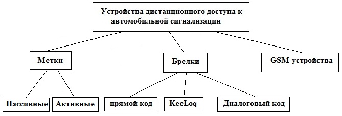
1) conventional trinkets with a one-way / two-way data channel - each of you surely has it. We press the button - the car is disarmed and the doors are unlocked. Click again - the doors are locked, the car is armed. When disarming / arming, the key fob sends a fixed unique code to the alarm (usually at a frequency of 433 MHz). The alarm checks the code in its database - if it matches, the code is accepted. The disadvantage is obvious - when using code grabbers, we listen to the broadcast, and at the moment when the owner of the car presses the key fob button, we just stupidly write down the code that the key fob broadcasts. In the future, an attacker can play this code and unlock the machine.
2) The further development of signaling in this direction was KeeLoq “jumping code” technology - here each time the code changes, and if we intercept the transmitted code with a grabber-code, this will not help us. Nevertheless, attackers and KeeLoq found an approach. The physical mathematical realization nullifies all the mathematical power of this technology - no one is trying to pick up the code. Instead, the package is spoiled, remembered, and transmitted the next time. The fact is that every bit of the KeeLoq sending is encoded with three bits. The first bit is 0, the next significant bit, and the last is 1. If the grabber turns on the transmitter in place of the third bit (jam the alarm receiver), then the signaling packet will be damaged and will be rejected. In this way, we will remember the alarm code, and in the future we will be able to use it (if, of course, Prior to this, the alarm will not successfully accept the next parcel from the remote control). You can also take into account the fact that the transmitter sends 3 identical packages. You can drown out the first half of the first package and the second half of the second, third completely - the transmission will reject the alarm, and we will have a working code. In the end, KeeLoq's math was really strong, but it all came to naught with a physical implementation
3) KeeLoq was replaced by the technology of the dialog code (using asymmetric encryption algorithms and the frequency of 2.4 GHz), which is now used in modern signaling systems. No one has yet been able to crack it, and alarm manufacturers are so sure of the break-in resistance of this technology that the same StarLine offers 1 million rubles to anyone who succeeds in breaking such an alarm. This million rubles has not yet been paid to anyone. Let's see how the communication between the key fob and the alarm goes: When registering a new key fob, the key fob public key is transferred to the alarm memory, and the Diffie-Hellman algorithm is used to transfer the keys on open communication lines.
Implementing it yourself is quite realistic, albeit quite expensive. In this regard, you can look at the STM32W microcontrollers, which have a hardware-based AES encryption accelerator that works with 128-bit keys and a 2.4 GHz transceiver. STM32W allows you to work in Wi-Fi, ZigBee, Bluetooth networks and in sleep mode, it has a consumption of about 1 μA, which allows you to use it in key fobs. There are ready-made debugging kits that allow you to quickly learn its wireless capabilities (~ $ 50).
4) RFID tags - used for contactless access (“hands-free”), communication range - up to 10 meters. No need to get out of your pocket and press the button - if the mark is in the range of the alarm receiver, the car is disarmed. Passive tags represent they do not have their own power source, they receive energy through the air from the alarm system by inducing currents on the built-in antenna. Active - have a built-in battery, which reduces the power of the alarm reader and increases the range of communications. Basically, the tags work at a frequency of 2.4 GHz (since with increasing frequency the communication range increases), and the communication range with the alarm reader is up to 10 m.
5) Relatively recently, GSM devices began to be used in automobile ACSs - disarming / arming from cell phones, smartphones. And increasingly, looking at the future of car alarms, they talk about a complete rejection of key fobs in favor of GSM-devices - smartphones, cell phones. But in its pure form, this idea stumbles on a rake: there is no 100% coverage of the territory with cellular communications, there is a high probability of staying in a remote area with a locked car and a dead smartphone, the need to pay for communication. Plus, the users themselves are not yet ready to abandon the use of trinkets. Nevertheless, everything is moving towards the fact that soon we will come to a bunch of label + smartphone, and the use of trinkets will remain in the past.
In the case of using smartphones, it is possible to negate the main disadvantages - the gsm-connection charge and insufficient network coverage - by providing a Wi-Fi signaling module, which will be discussed below.
Wi-Fi access to signaling is provided
in modern mobile devices - phones and smartphones, and also netbooks and tablets - there is built-in Wi-Fi support, which can be used for remote direct access to our device, bypassing the server. Consider the most popular solution - the $ 22 WiFi module MRF24WB0MA from Microchip:
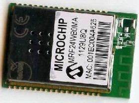
- alas, we can’t connect it directly to our STM32, to use the module you will have to use a layer in the form of a PIC microcontroller (however, this will not significantly affect the price of the product), onto which we will upload a library implementing the TCP / IP stack from Microchip, which supports this module (however, for me this is not a problem, because I went up on PICs). The module itself is connected to the PIC via SPI, and already with the PIC it can be connected to our STM32 via spi / i2c / uart. The module itself has good functionality: built-in accelerator for AES / RC4, support for WEP, WPA-PSK, WPA-2-PSK. Range - up to 400m. consumption in sleep mode - 250 μA, hibernation - <0.1 μA. The library itself, among other things, has SSL support. By the way, I note that this library works the same way with both Wi-Fi Microchip modules and wired Ethernet (ENC28J60, etc. ) That is, when you work with this library, there is no difference if you work with a Wi-Fi or Ethernet module - the software interface is the same. You can read more about the libraryhere .
Software Development for Mobile Devices
Starting from this section, I abstract from the hardware implementation and will exclusively consider the software implementation of satellite car alarms on the server side and mobile devices.

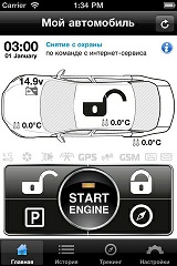
Recently, mobile GSM devices based on the operating systems iOS (iPhone, iPad), Android, Windows Mobile, Blackberry, etc. have gained widespread popularity, and in recent years, an increasingly large range of household equipment has begun to grow in support for remote control from these devices. Manufacturers of car GSM-alarms, which quickly released applications that allow you to control and monitor cars from smartphones, did not stand aside. You can add such support to our alarm system, which already knows how to interact with the WEB server (see the section on using the SIM900 TCP / IP stack). The WEB server will act as an intermediary here - your mobile application connects to the server, and the server already interacts directly with the alarm system.
1) View on the map (Google.Maps, Yandex.Maps or OpenStreetMaps) the current position of the car
2) On-board computer - readings of sensors, temperature, voltage, how much is left before consumables are replaced, etc.
3) Arming / disarming
4) Remote engine start
5) Optional - view photos from cameras, etc.
The main stumbling block is the need to learn Objective-C and other languages to develop your mobile application for various platforms. Universal solutions like PhoneGap come to the rescue:

PhoneGap is an OpenSource environment that allows cross-platform development of applications for almost all well-known platforms (iOS, Android, etc.) in HTML5 using Mobile jQuery and CSS. The application is actually a web page that has access to the hardware peripherals of the smartphone (accelerometer, camera, GPS, etc.). PhoneGap is not without drawbacks, and for industrial applications, you still need to abandon the cross-platform approach in favor of the native - Objective-C. But at first it serves a good service (especially to those who are already associated with web development by type of activity), allowing them to provide support for mobile devices with "little blood".
You can read more about PhoneGap here
. Web server software
It's time to figure out the implementation of a web server that will mediate the interaction of signaling and devices connected to the Internet (smartphones, netbooks, tablets, regular computers, etc.). In our case, the web server performs the following functions:
1) Receives data from gsm alarms and gives them the current settings
2) Provides a web interface to alarm owners for monitoring and alarm management
3) Provides access to data from mobile applications (for devices running iOS, Android, etc.)
4) Provides an XML API for uploading data to client servers. For
illustrative implementation examples, see http://panel.car-online.ru/ and https: // p-on. com /
For hosting, it is better to choose cloud hosting - in this case you are not rigidly limited in resources, there is the possibility of flexible scaling of computing power. Unlike VPS hosting, here payment is made only for actually consumed resources (with VPS, you have to pay for resources that are idle most of the time + a strict resource limit).
Further about the structure of server applications. At first, and at low load, the most simple and mundane solution is LAMP (Linux-Apache-MySQL-PHP).
But those who are sharpened by such an approach very quickly begin to regret it. :-)
Time passes, the load grows, and pretty quickly the moment comes when the current architecture ceases to cope with its tasks. Then thoughts about Highload come. There is far from one approach, and as an example I will consider the Open-Source bundle nginx + varnish + memcached + php-fpm + eaccelerator (+ PHP, + MySQL). A little bit about what it is.
• Nginx - a web server that is usually used to render static. There is a popular architecture in which nginx acts as a front-end, proxying requests for dynamic pages on Apache (back-end), on which server scripts are already spinning. But Apache can (and should) be completely abandoned by hanging its function on the more lightweight nginx.
• php-fpm - PHP FastCGI Process Manager - acts in our case as the "connecting bridge" of PHP for working with nginx. Php-fpm allows you to effectively use PHP in FastCGI mode on highload projects.
• eAccelerator - a tool that allows you to not interpret the PHP code each time. Once we performed the interpretation - and we keep the code in memory for later use - there is a saving in processor time and access to disk resources.
• Memcached - server for caching data in RAM. Database servers like MySQL are good, but they spend time executing queries and reading from slow storage devices - hard drives. Much faster, data can be selected from RAM, so the logic here is: We make a request to memcached, if the required data is not (empty), then we make a request to the MySQL database server, and send the response to memcached. Those. MySQL acts as a slow back-end solution, and Memcached as a fast front-end. We turn to the back-end only once - to place data in the front-end and access this data only through the front-end (until, of course, they lose their relevance).
• Varnish is an HTTP accelerator that allows you to cache content. In some ways this is an analogue of Memcached, then for significantly large amounts of data. Varnish saves pages in virtual memory and, if necessary, drops them onto the hard drive. We can logically divide each page into its constituent blocks (footer, header, news block, etc.) and specify our caching rules for each of the blocks. In the end, we get a gain in the speed of returning pages, and unload the back-end part of the server from repeated requests.
Of the additional measures - look in the direction of switching MySQL to tmpfs, build table indices, use the InnoDB data storage engine (suitable in our particular case), configure sysctl.
Let's see one of the possible architecture schemes, with SSI inclusions. In the first case, initially, we have an empty cache, the back-end is included in the case (PHP + MySQL), and in the second it is not used, we get the data from Varnish and Memcached:
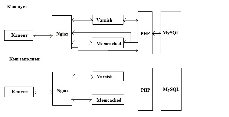
- in the first case, nginx refers to Varnish for a page that does not exist in cache - because the request goes to the Back-end (PHP + MySQL). The cache of SSI inclusions is stored in Memcached, and so on. is empty there, then Nginx makes a call to the back-end part, which gives the result to nginx and simultaneously stores in the cache via Memcached.
In the second case, we no longer pull the back-end part, the data is taken from the Varnish and Memcached cache.
The above is not a universal solution - the Highload architecture of the project is its own for each specific task - it is required to implement the solution on the test server and conduct load testing - try to maximize the working situation, taking into account the most predicted volumes of load growth. And you can never stop there. “I did everything, everything works, you can breathe a sigh of relief and relax” - this does not happen. All the time you need to think one step ahead, predicting the possible development of the current situation.
Ways of further development
The device already performs many functions - this is an alarm system, an on-board computer, and a telecommunication service (ERA-GLONASS / eCall) in one bottle, with access via the Internet. Designed for both cars and trucks, and for real estate. But there is no limit to perfection. If we want to supply our car with electronics, we have to purchase disparate devices - a radio tape recorder, a navigator, a video recorder, etc. They have to stick around the windshield, which narrows the visible area and attracts unclean people to the car once again. There is no decent device on the market now - a “media combine” that replaces the above devices, creates a single entry point for all functions and integrates well with standard equipment of cars. Even China has not yet succeeded in this regard.

- A solution on ARM11 running WinCE with a gsm modem, a GPS / Glonass receiver, which allows you to connect audio-video sources and displays images on separate displays as well as on regular cars. It integrates with the standard systems of Lexus / Toyota / Subaru / Nissan and other cars. The idea is not bad, this is a really significant breakthrough. A breakthrough brought to naught by the implementation - the device is still too damp, having work problems and implementation shortcomings, and a high price.
Thus, this area still remains undeveloped, there are no worthy, strong and affordable solutions for most. The information provided in this article on the development of satellite signaling can be a good springboard for the development of a competitive device. As a basis, a single-board Raspberry Pi computer with ARM11 immediately suggests itself, the functional equipment of which can be expanded. :-)
As a conclusion
So we just literally in a nutshell on the fingers of the main points in the development of automotive satellite GSM-alarms, from and to. :-) On my own example I was convinced that the devil is not so terrible as he is painted, and that you can really do everything yourself, you only need time and patience. In fact, it’s important to remember the golden rule: “less is better, but better”. In an effort to embrace the immensity, to endow their device with as much functionality as possible, manufacturers often lose in quality of execution. It’s better to draw a circle for yourself, cut down your Wishlist, make it smaller, but with high quality and dignity, having worked out all the nuances in detail.
In the article I considered only satellite systems, leaving aside radio search engines. On the one hand, radio search systems win over satellite ones - less power consumption, work in closed rooms (the signal breaks through metal boxes, underground garages, etc.), the transmitter can be placed in the car anywhere (in doors, hidden body cavities, etc.). d.). But on the other hand, there are also disadvantages: insufficient coverage of the territory with radio beacons, a relatively high monthly fee, the inability to display the position of the protected object on the map, the inability to develop your own radio search device - unless you put your own radio beacons in the city, which is very expensive) Plus the advantages of radio search systems you can’t demonstrate to the end consumer by the example of the operation of the device. Few of you will decide to pay a tangible amount of money for an assembly that you will not use for your own purposes, whose work will not be visible to him. Those. It is important for the consumer to “touch” what he gains in business. Satellite systems in this regard significantly benefit. And there is nothing surprising in the fact that they noticeably benefit from sales, and radio search engines still remain in the background, despite all their advantages.
As for the car alarm equipment, I strongly recommend not to be satisfied with the standard equipment, but install GPS beacons in hidden cavities. In addition, to cover the glass with an armored film and insert pins in the doors is not only an additional measure against theft of the car, but also a real protection against theft of things in the cabin. In addition, the de facto standard has long been the installation of an electric hood lock and a Garant-type lock on the steering wheel + digital relays (based on current keys) on the main circuits of the machine, which are blocked if the alarm is disabled - if the alarm supports their installation. We often feel sorry for the money - we wave, we think that the car is not worth it. And we regret it only when it’s too late to change anything ...
PS I think many of you noticed that the video at the very beginning of the article was “replayed” to attract customers - the alarm system, of course, does not send any data to the satellite, such alarms are called satellite only because they receive data from GPS / Glonass satellites. To send information to satellites, you need a good such plate. ;)
UPD 09/06/2012: 2G modules (sim900) can no longer be used in ERA-GLONASS systems in accordance with the new GOST R 54620-2011, this requires 3G modules (for example, work with ERA-GLONASS supports the 3G SIM5320 module) .
References
1) Satellite speedometer on STM32F1 and FreeRTOS
2) Draft national standards ERA-GLONASS.I express gratitude to the director of subscriber device development service of the Federal Operator “NIS-GLONASS” Domaratskiy Ya. A. for the materials provided.
3) Sources of the car GPS-tracker based on ATmega128
4) Sources of gsm-alarm for 2 SIM cards, iButton, dtmf-decoder
5) Sources of GPS-tracker on STM32
6) Sources of GPS-tracker on STM32F10x
6) GOST R 54620-2011 “Automotive emergency call system. General technical requirements "
7) Order of the Ministry of Transport of Russia dated July 31, 2012 N 285 - it is interesting to describe the protocol for transmitting telematic information and the procedure for calling emergency services
I finally decided to write the continuation of the article “Satellite Speedometer on STM32F1 and FreeRTOS” .
Let us consider how to make a car satellite alarm with a web-based interface with your own hands - the main ideas, the element base, the technical details of implementation. I note right away that the cost is at the level of one and a half thousand rubles (in the basic version), while industrial analogues (together with the installation) go in the region of 30-50 thousand rubles. There is no subscription fee - there are only expenses for mobile communication (about 100 rubles per month. With a competent approach to minimizing the transmitted traffic, ~ 60 rubles, or even less) will go per month. Thanks to the support of Glonass, an additional advantage appears in connection with the expected 100% equipment of the Russian fleet with Glonass systems. And at the same time, the described device carries innovative capabilities that are not yet on the market.
The device described below is universal - with the same success it can be installed and work both on the Zhiguli and on Lexus - both on mobile objects (cars, trucks) and stationary (houses, cottages, etc. ) Performs 3 main functions:
*Information - an analogue of Volvo On Call technology. Being at a considerable distance, you stay in touch with your car, if you have any device with Internet access (computer, netbook, iPhone, iPad, Android device, etc.) - find the location of your car, start the engine remotely, get information about its technical condition, etc. Management and monitoring of the machine is carried out through SMS / voice calls (dtmf) / site. The site is an Internet portal to which objects equipped with this device automatically “dump” information about their current state and take settings for their work from it. It is also an automotive social network (similar to Toyota Friends) for the interaction of objects (cars, houses) and people.
* Security - includes:
a) label with a 2.4GHz dialogue code based on STM32W, for automatic access to the object.
b) protection against jamming of the gsm signal (constant monitoring of the communication channel by the server + detection of the fact of jamming from the side of the alarm itself)
c) function of gsm / gps / glonass tracker - if the car is stolen or put into a parking lot, you can find out its current location.
d) hidden video surveillance - via rs485, video cameras consisting of STM32F4 and cmos cameras on board are connected with the alarm system.
d) digital relays - even by physically removing or disabling the alarm, the attacker will not achieve anything - the relays will de-energize vital circuits, and they can no longer be activated, even by directly supplying power to them. Also, digital relays control the pins in the doors - even if an attacker breaks the glass and / or breaks the lock cylinder - he won’t be able to open the door, even after breaking its lock - the electronic pins in the doors, which can only be unlocked by an alarm, will open the door.
e) as additional equipment, 1 or several gsm / gps / glonass beacons, also home-made, are used. Because for the reasons described below, the use of signaling alone is not enough. It is also recommended to use a hood lock, a steering lock (for example, a Guarantor), an armor film for glass (breaking glass to steal your things from the passenger compartment or penetrate inside will be extremely problematic - it protects even from air gun bullets)
*Rescue - a car equipped with this device will be able to independently call emergency services, even if the driver and his passengers are no longer able to take any action. To implement this feature, the device has support for eCall / ERA-Glonass technology. The installation of such devices is predicted to be able to save 2,500 lives a year in Europe annually, 4,000 lives a year in Russia and reduce the effects of injuries in road accidents by 14%.
* Logistics - for companies engaged in cargo transportation. Monitoring and tracking the movement of vehicles, accounting for fuel consumption in the fleet, etc.
To more clearly show what will be discussed, I’ll give a video from the industrial version of this device (which, incidentally, has fewer features at a significantly higher price):
And now - how to independently implement all this, ideas in general terms. In the end, consider the implementation on STM32 microcontrollers.
1. The general structure of the system.
- as I wrote earlier, the device is suitable for use not only in mobile objects (cars, trucks, etc. - “Smart Car”), but also in stationary (apartments, houses, cottages - “Smart House”). In general, automobile satellite alarms, as practice shows, are a good replacement for Smart Home systems for the automation and protection of apartments, cottages and other real estate. Of course, they cannot compete with such Smart Home systems as LonWorks, Legrand and Bticino, but they can quite solve the tasks that are of priority for the consumer when automating their home - security, remote monitoring and control, video surveillance, etc. Not always a consumer is ready to pay for automation the money that systems like LonWorks cost — he needs a budget solution, which can be a car satellite alarm. As an illustrative example, you can cite the resourcehttp://home-online.ru/solutions.html
In the case of Smart Car, the device is housed in a metal case that can withstand loads of up to 40G, which houses the alarm itself and a backup battery. This is a requirement of the ERA-Glonass standard - in the event of an accident and subsequent possible fire, the device must be able to contact emergency services and transmit the coordinates of the car, even if the driver and his passengers are no longer able to take any action on their part. In addition, a SIM chip is used instead of a SIM card (for more details, see the “SIM900 GSM module” section below).
In the case of “Smart Home” application, the device is placed in a conventional compact plastic case with a battery for placement in a place hidden to the attacker, while its power unit is placed in the case for mounting the electrical cabinet of the property on a DIN rail:
Now, consider the structure of the device itself, in case of automobile application:
To collect data on the state of the car (engine speed, oil and liquid pressure sensors, etc.), a connection to the vehicle’s diagnostic connector is used using CA N / LIN. In the event that our device does not support this brand of car, a connection is used directly to the sensors and actuators of the car - tachometer / generator, nozzles, oil pressure sensors, coolant level, etc.
You can do without the immobilizer crawler, if the immobilizer supports remote start - this is set in its settings. Otherwise, you will most likely have to sacrifice one of the tags and apply the crawler.
My alarm is configured via USB - I use the USB CDC class in STM32, so on the computer side the device is defined as a regular com port, and you can work with it through any terminal (I use Putty).
Volume sensor - a standard external sensor is used, and you can use an accelerometer in the device itself, for example, LIS203DL (the plus is that this accelerometer is installed on the stm32f4-discovery debug board and there are well-documented examples of working with it).
To implement the autostart function in the case of manual transmission, we must be sure that the machine is not in gear. To do this, the user must either leave the car and arm it without turning off the engine (arming with the engine running), or install reed switches on the gearbox (the implementation is described here )
Cameras on the STM32F4 The
elemental base of the cameras is represented by the STM32F407 microcontroller + CMOS camera + external memory. They are connected to the main signaling unit via the RS-485 interface (at the physical level, and ModBus is used at the application level ). The best option is to place the cameras as follows:
Cameras work in photography mode. The STM32F4 microcontroller was not chosen randomly - it has a built-in synchronous parallel DCMI camera interface, which allows connecting cmos-cameras up to 1 megapixel. Among others, it has a Snapshot mode, which is used. Using the direct memory access (DMA) mechanism, data from the camera is immediately placed in an array in external memory connected via the FSMC interface of the microcontroller - while the computing resources of the kernel are not used.
By the way, the use of a cmos camera with conventional microcontrollers is complicated by the fact that the same OV7670 camera does not know how to transmit data with a frequency of less than 10 MHz + the data from it needs to be placed somewhere. Therefore, to use cameras with conventional microcontrollers (as well as FPGAs), FIFO buffers are often used, for example AL422B, the memory capacity of which is enough to store 1 frame of the image from the camera: The device of the main signaling unit The main components of the main unit are the microcontroller stm32f103, gps / glonass module , gsm module SIM900. GPS / Glonass module At the moment I use the well-known gps EB500, but it is planned to switch to the GPS / Glonass module Geos-3M
. If we compare it with the ML8088s / GL8088s, nv-08-c, then it compares favorably with the energy consumption from the first (judging by the engineering samples), and from the second with the price ($ 28 retail, $ 15 wholesale). By the way, it is planned to use GPS / Glonass-module Geos-1M in ё-mobiles.
Using a dual GPS / Glonass module instead of ordinary GPS gives us two main advantages:
1) Using the GPS + Glonass mode allows you to increase the accuracy and success of determining coordinates (because we have more satellites available - not only GPS, but also Glonass).
2) The commercialization of Glonass technology is gaining momentum. Already at the legislative level, the installation of Glonass terminals is required for installation on a number of vehicles. Therefore, the support of Glonass in an automobile device is an additional competitive advantage that ensures its attractiveness in the market.
Working with the module does not cause problems - the module takes care of all the mathematical processing, outputting text strings with ready data (NMEA protocol). About how to organize their analysis and work with the module on the STM32 microcontroller, I wrote in a previous article, “Satellite Speedometer on STM32F1 and FreeRTOS” . By the way, the Geos-3M module supports data output in binary form.
When using such modules, the main problem is the increased noise level in the parking lot, which is expressed in the drift of coordinates and speed on a stationary object. And overnight the car, if you do not take additional measures, can wind up more than one circle on the map, while remaining in reality motionless all the time. The best solution to this problem without the use of additional components that I know of is the control of azimuth changes with the simultaneous calculation of coordinates (not to take into account with a small change) - with this approach, we do not take into account garbage, and we get memory and traffic savings.
In any case, any kind of mathematical processing of GPS / Glonass module readings is not ideal - even in the best case, it turns out that we do not take into account the low speed and a small change in coordinates. The use of a 3-axis gyroscope and an automobile speedometer can jointly solve this problem in the case of automotive applications. It can be combined with the Glonass / GPS module. As such a gyroscope, you can take, for example, the L3G4200D ($ 19). For automotive applications, the A3G4250D gyroscope has already been announced, but it is not yet available for sale. Such a gyroscope works on the I2C / SPI bus:
So, how does the gyroscope and speedometer help us?
a) we get the opportunity to quite easily defeat the drift in the parking lot - discard false data on the speed and change of coordinates in the parking lot with GPS / Glonass
b) If GPS / Glonass signals disappear, we get the opportunity to continue to conduct geographical positioning by speedometer and gyroscope - continue to track.
In the parking mode, when the car is stationary, the GPS / Glonass module tells us that we are moving at a low speed, the coordinates are drifting. But we get zeros from the gyroscope, which gives us reason to believe that we are standing still and the readings of the module can be ignored. If the GPS / Glonass signal disappears in motion, we take speed information from the speedometer, and turn information (angular speeds) from the gyroscope.
In terms of implementation, it’s essentially not important for us which speed sensor is used and where to get it from in the car. Almost everywhere, the amplitude of the speed signal is 12 volts, the difference is only in the number of pulses per second. Here you can simply enter the self-calibration - in the GPS / Glonass movement, automatically determine how many pulses per 1 meter of the path, and memorize the resulting constant.
It is also necessary to enter the temperature calibration of the gyroscope by GPS / Glonass, as its side is temperature drift.
It should be noted here that calculating the path according to the gyroscope and speedometer by the Cortex M3 is a very dubious task. The data must be sent to the server, on which the calculation will already be made. But in case we are ready to abandon Glonass, leaving only GPS, you can look at the LEA-6R GPS modules - it has a DR (dead reconing) function that allows you to connect directly to the module additional channels for receiving path information - a gyroscope and speedometer. Accordingly, both the microcontroller and the server are unloaded in this case in terms of calculating coordinates - the module itself is already engaged in this, providing ready-made NMEA data. Which significantly reduces the time and laboriousness of developing a finished device. It is a pity, but such decisions supporting Glonass are not yet visible on the horizon .: - (
And now - it's time to consider working with a GSM modem.
GSM / GPRS module SIM900
Earlier, in embedded systems, the use of the sim300 gsm module was common, but soon he was replaced by sim900 ($ 21), and after a while, his lightweight budget version sim900r began to be released (unlike sim900, this is a dual-band module with reduced program memory and with restrictions on use in countries - only in Russia and border countries). SIM900 is a quad-band (850/900/1800/1900) GSM / GPRS module with an integrated TCP / IP stack. Allows you to send MMS messages, has built-in support for the application layer protocols HTTP, FTP, and in the latest firmware - DTMF decoding, the ability to detect jamming of a GSM signal (Jamming Detection) and support for eCall / ERA-GLONASS rescue systems (the latter will be described in more detail below ) You can control the modem using AT commands,
Raising a board for this module for debugging on your own is a thankless task, especially since the debugging board for this module is quite inexpensive - $ 65, so I recommend taking it:
To support Era-Glonass, DTMF decoding, etc. you need to update the firmware - to do this, contact the distributor in your region (I contacted MT-System), and then flash it through the debug port.
It is more convenient to debug work with the module from a computer. Fortunately, I initially laid down USB support for the device in the device for setting the settings, then I did this: I connected the library from ST to implement the USB CDC class, which made it possible to communicate with the device through any terminal that works with a serial port (the device is seen in the system as a virtual com- port). The device sends commands to the SIM900 module, while the module includes echo retry - i.e. everything that is sent to him, he sends back, along with the answer. And the microcontroller sends the entire response from UART from SIM900 to USB to my terminal box. Those. in the process of interaction between the device and SIM900, the whole process of communication is clearly visible on the screen + from the terminal it becomes possible to control the process of communication by setting unique breakpoints.
Getting started with the SIM900 module is described here and here , so I ’ll focus on the most interesting points:
SIM900: GPRS
By default, the device sends data (current coordinates, vehicle speed, etc.) to the web server and receives settings from it. Let's look at a simple example of how you can send data via HTTP to your server (the operator in our case is MTS): SIM900: Protection against jamming a GSM signal An attacker can safely disrupt the connection of our device with the server via a GSM channel, and for this It has 3 ways: 1) GSM jamming
< AT+CREG? // Проверяем, зарегистрирован ли модуль в сети


< AT+CGATT=1 // Просим модуль включить GPRS


< AT+CSTT=”internet.mts.ru” // Задаём точку доступа.


//Если успешно – модем переходит в состояние IP START


< AT+CIICR // Работает только, когда модем в состоянии IP START. Открывает GPRS-сессию. Если удачно – модем переходит в состояние IP GPRSACT


< AT+CIFSR // Узнаём свой IP-адрес


< AT+CIPHEAD // Просим модем добавлять IP-заголовок к получаемым данным


< AT+CIPSTART=”TCP”,”www.tzit.ru”,”80” // Подключаемся к нашему серверу, допустимо только если модем в состояниях IP INITIAL или IP START


< AT+CIPSEND // отправлять только после получения от модема строки CONNECT OK. Говорим модему, что далее последуют данные, которые нужно отправить на указанный нами выше сервер. Наши данные отправляем только после получения строки «> »:


< GET /cgi-bin/sim900.pl?device_id=123&gsm_lac=111&gsm_ci=222&led=0


< Host: www.tzit.ru HTTP/1.0


< // На сервере для домена www.tzit.ru по протоколу HTTP 1.0 вызываем скрипт /cgi-bin/sim900.pl и методом GET передаём ему параметры device_id,gsm_lac,gsm_ci и led
- Using such a simple device costing $ 119, you can drown 3G / GSM / CDMA modems in a radius of 5-20 meters. And the disturbing communication channel of satellite gsm signaling with the server will be broken.
2) Substitution of the base station of a cellular operator
There are devices that fit in a briefcase and allow you to impersonate a base station of a cellular network: the
device’s GSM modem will not be able to distinguish a real base station from a fake mobile one, and in case of an alarm it will not be able to send data via an alarm channel.
3) Cloning a SIM card.
- the number used by the gsm alarm system has a second SIM card, which is in the hands of the attackers. And if you silence the alarm signal with the jammer from item 1, then the device with this number (from the attacker) will be available and will not give alarms. If the alarm check is based on periodic dialing, then the dialing will be carried out on a fake SIM card, and it will not cause an alarm.
4) Field detector for detecting radio transmitters (including GSM devices)
- used to localize the installed alarm. You can buy such a miracle device for $ 43:
- allows you to identify radio transmitters emitting in the range of 1 MHz-2.6 GHz. The screen displays the frequency of the device and the signal level, which allows you to find the installation location of the alarm and neutralize it.
In order to protect against item 4, a car is installed in addition to the standard alarm gps / gsm-beacons, which will be discussed in the section “SIM900: Using user applications. GPS / Glonass - beacons. ".
To protect against items 1 and 3, the SIM900 module supports the Jamming Detection function, which is designed to detect attempts to jam the signal - the AT + SJDR command is used for this. If the modem is jammed, the message “+ SJDR: JAMMING DETECTED” will be displayed. Of course, the modem will not have time to contact the server and transmit alarm data. But the device will be able to turn on the siren, block the car and remember that it was jammed - after the resumption of communication, this information will go to the server.
To protect against all of the above points in modern satellite gsm alarms, GSM channel control is used. The bottom line is that the gsm modem communicates with the server with a given frequency - for example, sends data via HTTP. If within the last N minutes the modem has not contacted the server - this is an occasion to raise an alarm and call / send SMS from the server to the owner of the machine. Of course, this is not a panacea for 100% of cases - somewhere just a bad reception of a GSM signal. In other cases, an attacker can affect the human psyche - periodically dimming the signal and forcing the owner of the car to run out to his car. After some time, the owner will get tired of it and he will turn off the control of the communication channel, thereby giving the hijacker a green light. Nevertheless, the control of the communication channel is a tangible help in solving the problem of protection against theft.
SIM900: Receiving coordinates in the absence of GPS / Glonass signals
About the current location of the car, we get the coordinates from GPS / Glonass satellites. But a situation may arise in which obtaining these coordinates is impossible (for example, there is no signal). In this case, the option of calculating the coordinates through a bunch of speedometer + gyroscope I have already considered above. But there is another solution - the base stations of the mobile operator may come to our aid, one of which we are connected to. From base stations we can receive information such as LAC and CELLID (area code and base station identifier, respectively). This information uniquely identifies this base station, among others, the current mobile operator. And the coordinates of the base stations are widely known. Therefore, knowing which base station the modem is connected to, you can determine the geographical coordinates (longitude and width) of this station, and thereby the approximate coordinates of the modem itself. The geographic coordinates of the lac and cellid base stations can be obtained through the Yandex API, Google, opencellid.org, location-api.com. By the way, mobile operators do not publish the coordinates of their base stations in the public domain. Therefore, the same Yandex receives this information from its users who have downloaded Yandex applications and have a GPS receiver in their phone. The Yandex application receives the cellid and lac of the base station from the gsm modem of the phone, and the current geographic coordinates from the gps receiver and sends it to the Yandex server - this way the lists of geographic coordinates of the base stations Beeline, MTS and Megafon are replenished. Google, opencellid.org, location-api.com. By the way, mobile operators do not publish the coordinates of their base stations in the public domain. Therefore, the same Yandex receives this information from its users who have downloaded Yandex applications and have a GPS receiver in their phone. The Yandex application receives the cellid and lac of the base station from the gsm modem of the phone, and the current geographic coordinates from the gps receiver and sends it to the Yandex server - this way the lists of geographic coordinates of the base stations Beeline, MTS and Megafon are replenished. Google, opencellid.org, location-api.com. By the way, mobile operators do not publish the coordinates of their base stations in the public domain. Therefore, the same Yandex receives this information from its users who have downloaded Yandex applications and have a GPS receiver in their phone. The Yandex application receives the cellid and lac of the base station from the gsm modem of the phone, and the current geographic coordinates from the gps receiver and sends it to the Yandex server - this way the lists of geographic coordinates of the base stations Beeline, MTS and Megafon are replenished.
So, we want to determine our coordinates by GSM. To do this, the SIM900 module needs to issue the AT + CREG = 2 command - it will give a response in + CREG format:
As a result, we issue a map with a shaded area to the user on the site, which shows the approximate location of the car based on gsm coordinates.
AT + CIPGSMLOC command appeared in SIM900 modems not so long ago, which immediately gives out immediately the geographical coordinates of the gsm network. But it does not carry anything fundamentally new in itself - this team does everything that I wrote above. Receives lac, ci, sends them to Google and returns the result.
At the same time, I note that some modems have the ability to sequentially connect to all in the BS in the field of visibility. This can be used to clarify the gsm coordinates - in this case, we can find out lac, ci of all the nearest BS, find out the geographical coordinates from them - they will be the vertices of the polygon in which our module is located:
SIM900: Using custom applications. GPS / Glonass - beacons.
Car satellite alarms are, of course, good. But they can find and deactivate it. For example, using the field detector discussed above. Gps / gsm beacons come to the rescue, which are miniature devices with a GPS (or GPS / Glonass) receiver, GSM modem and battery. Such beacons are difficult to detect visually, because they hide well in the hidden places of the car. It’s difficult to detect them with a field detector. most of the time such a lighthouse simply sleeps, only occasionally waking up to register on the network, transfer its coordinates to the server, and fall asleep again.
The question may arise - what about the microcontroller? The answer is that it is not needed. Modern GSM modems have a special memory area for launching user applications. For example, Sierra Wireless modems use the OpenAT operating system, in which your programs can run. And SIM900 supports Embedded AT technology - you simply create your program in the SIM900DevIDE environment, download it with firmware to the modem - and enjoy life. There is no need to spend money on a separate controller - the modem will take the data from the GPS / Glonass receiver itself and send it to your server. Along with the SIM900DevIDE environment, there are already examples of programs, so you won’t have to write your application from scratch.
SIM900: eCall / ERA-GLONASS Rescue Systems.
ERA-Glonass is a system designed to reduce mortality and injuries on Russian roads, based on the use of Glonass. If a person gets into an accident - a car equipped with a terminal of this system is capable of calling emergency services independently without human intervention. There is also a manual ability to call them by pressing the SOS button (something similar is in Volvo On Call and Lexus Link, but there it is paid services + the cost of the equipment itself is quite high). In order for cars coming from the EU countries to us to be able to receive emergency assistance in Russia, and vice versa, so that our car equipped with the ERA-GLONASS terminal can work with Western infrastructure when traveling abroad, there is full compatibility with the European system eCall. Those. if we have the support of ERA-GLONASS, then being abroad in the EU countries, we will be able to use the eCall emergency response system. According to preliminary forecasts, the use of ERA-Glonass / eCall system terminals will save 2,500 lives in Europe annually, 4,000 lives in Russia, and reduce the consequences of accidents by about 14%. So far, there is only testing and deployment of ERA-Glonass and eCall systems. The final commissioning of eCall is scheduled for 2014, and ERA-Glonass - at the end of 2013 (we are optimistic, however!). Since 2013, all cars produced from the assembly line should already have the support of ERA-GLONASS. But more than a dozen years will pass before most of our population will have cars with an already built-in ERA-GLONASS / eCall terminal,
The ERA-GLONASS terminal is not difficult to make by yourself - for this, modems have already appeared that support the technology of transmitting data via the voice channel - the in-band modem function. Let's see how it works:
But first, answer the question - why not just use regular GPRS, SMS? The fact is that they introduce a significant delay in the transmission of data. In in-band modem data is transmitted instantly, such a call will be allocated the highest priority by the mobile operator, even in the event of a network congestion. If the network is congested, then active calls of other subscribers will be disconnected so that your terminal can contact 112 service.
In the event of an accident (determined by the readings of the car’s sensors), or if you press the SOS button yourself, we make an emergency call to 112 and send it to the PSAP server (in Russia, to the PSAP server of the federal operator NIS-GLONASS, which supports version 3GPP 8.6 .0 / 9.4.0. PSAP stands for Public Service Answering Point) An MSD message (MSD-Minimum Set of Data, with a limit of 140 bytes, which contains the following information:
1) Control data: is the call test, is it possible to trust the indicated geo-coordinates, type of vehicles (passenger car ample (class M1), city / intercity bus (M2-M3), light commercial vehicle (N1), truck (N2, N3) motorcycle - classes L1e-L7e)
2) Vehicle identification data: VIN-number of your car
3) Vehicle propulsion storage type: what your car drives (gas, diesel, gasoline, hydrogen, electric motor) - you can specify several values at the same time (if, for example, the car uses both gas and electric energy to move)
4) Time stamp: Indicate the current date, including seconds
5) Current location of vehicle: indicate the geographic longitude and width obtained from our GPS / Glonass module. If you don’t know, you can simply leave the field blank.
6) Direction of vehicle: the direction of movement of the machine along the magnetometer built into the terminal, in degrees, with 0 being magnetic north. The countdown is clockwise, in steps of 2 degrees. Those. if the deviation is 120 degrees from magnetic north, then we indicate the value 60 in MSD. Or just 0xFF if the direction of movement is not known.
7) Location delta with respect to vehicle Location, Location delta with respect to recentVehicleLocationN1: The difference in geographical coordinates between the current coordinates and those coordinates that were recorded at the time of the accident. These fields are also optional.
8) Number of passengers: the minimum known number of passengers. If we don’t know, specify 0xFF. It is automatically calculated as follows: in the car’s seat belts there are sensors that fix whether the seat belt is latched (for us this means that the passenger has taken the appropriate place) - the number of activated sensors and write in this field.
9) Optional additional data: any additional information (binary / bcd / xml / asn.1 / ascii), the format is not strictly regulated.
10) CRC32 - CRC32 checksum of our MSD message.
The total length of the MSD cannot exceed 140 bytes. The default connection is initiated by the client (i.e. us), but it can also be initiated by the service 112 PSAP server.
One of the first modems that implemented in-band modem for working with eCall / ERA-GLONASS was the Sierra Wireless company SL6087 modem. But a couple of months ago, such support appeared in the firmware for the SIMCom SIM900 modems used by me. Moreover, it is possible not only to send a ready-made MSD message: but also to transfer this function to the modem itself, indicating the values of the MSD message fields through AT commands: The operator of the ERA-GLONASS service will display this information as follows: For testing it’s not at all necessary to contact NIS-Glonass - you can organize a test PSAP server on your side with an OpenAT modem, you can read more here
AT+CMSD=”015C0681508204420014264000420D101404E80DA4C89A3B2F09905B6440E829F6829EC020301027D04303046460”

AT+CECALL="112",0
AT+CMSDFORMATID=1
AT+CMSDMESSAGEID=1
AT+CMSDCONTROL=1,0,1,1
AT+CMSDVIN="WM9VDSVDYA123456"
AT+CMSDSTORAGE=1,0,0,0,1,0
AT+CMSDTIMESTAMP=2011,7,12,17,28,14
AT+CMSDLOCATION="48.300333","11.617367"
AT+CMSDDIRECTION=14
AT+CMSDRECENT1="10","-10"
AT+CMSDRECENT2="10","-20"
AT+CMSDPASGNUM=2
AT+CMSDBUILD
AT+CECALL=”112”,0A device that implements this functionality is placed in a metal case that can withstand a load of 40G (after all, the device should function in the event of an accident) and has a built-in battery for autonomous operation.
Also, additional requirements apply to the SIM card - using a regular SIM card is not acceptable here, because in the event of an accident, the mechanical contact of the SIM card with the device can most likely be broken. Here their analogues come for use in embedded devices - SIM chips, which have two main advantages compared to SIM cards:
1) The best contact due to the lack of mechanical connections - the SIM chip is soldered to the board and not inserted mechanically into the holder,
2) An extended temperature range (-40 ... +105 degrees Celsius), as well as increased resistance to dust, selection, humidity, shock, corrosion, chemically aggressive environment.
Also, for SIM chips, mobile operators (MTS, Beeline, Megafon) provide an extended service (though not cheap) for M2M telemetry, for monitoring and monitoring devices equipped with this chip. It is possible, for example, to introduce restriction bars to prevent situations when an object is roaming and in this connection large amounts of funds begin to flow from the account.
In conclusion of this section, I add that the idea itself has many advantages, moreover, it is really useful and necessary, but for all that it is not without drawbacks. The infrastructure of Russia is not fully prepared for the implementation of this technology - only 97% of the territory is covered by cellular communications, therefore emergency assistance will not be available everywhere. Moreover, even in densely populated areas there are areas where cellular communication does not work or works very badly. For example, in South Butovo I know places where using cellular communication is quite problematic - sometimes it does not exist at all. It is impossible not to note negligence - it happens that when you call an ambulance at the police, you may not have to wait for the result, get a refusal to leave, although the situation is really urgent. Or do not get through at all. At all, many Russian government projects in the field of information technology turn out to be implemented in the “three with a minus” - take for example the State Services portal, which pleases us with enviable constancy with the “Communication error with the department” and “Internal server error”, moreover, at the very last stage of application, when I already spent a lot of time to hammer all the data ... But even if you can’t achieve 100% efficiency of this project, the implementation will not be meaningless, because in any case it will reduce mortality The level of injuries on the roads of our country will allow us to work with emergency services of other countries during international trips.
Remote access devices for alarms: tags, key fobs, gsm devices
In the current implementation, my device acts as a slave alarm. For remote door opening, a standard alarm system with its key fobs is used. But we will consider options for finalizing a home-made alarm system for remote access to an alarm system for remote monitoring, removing / arming, unlocking / locking doors, their strengths and weaknesses from a safety point of view (i.e., car ACS devices):
1) conventional trinkets with a one-way / two-way data channel - each of you surely has it. We press the button - the car is disarmed and the doors are unlocked. Click again - the doors are locked, the car is armed. When disarming / arming, the key fob sends a fixed unique code to the alarm (usually at a frequency of 433 MHz). The alarm checks the code in its database - if it matches, the code is accepted. The disadvantage is obvious - when using code grabbers, we listen to the broadcast, and at the moment when the owner of the car presses the key fob button, we just stupidly write down the code that the key fob broadcasts. In the future, an attacker can play this code and unlock the machine.
2) The further development of signaling in this direction was KeeLoq “jumping code” technology - here each time the code changes, and if we intercept the transmitted code with a grabber-code, this will not help us. Nevertheless, attackers and KeeLoq found an approach. The physical mathematical realization nullifies all the mathematical power of this technology - no one is trying to pick up the code. Instead, the package is spoiled, remembered, and transmitted the next time. The fact is that every bit of the KeeLoq sending is encoded with three bits. The first bit is 0, the next significant bit, and the last is 1. If the grabber turns on the transmitter in place of the third bit (jam the alarm receiver), then the signaling packet will be damaged and will be rejected. In this way, we will remember the alarm code, and in the future we will be able to use it (if, of course, Prior to this, the alarm will not successfully accept the next parcel from the remote control). You can also take into account the fact that the transmitter sends 3 identical packages. You can drown out the first half of the first package and the second half of the second, third completely - the transmission will reject the alarm, and we will have a working code. In the end, KeeLoq's math was really strong, but it all came to naught with a physical implementation
3) KeeLoq was replaced by the technology of the dialog code (using asymmetric encryption algorithms and the frequency of 2.4 GHz), which is now used in modern signaling systems. No one has yet been able to crack it, and alarm manufacturers are so sure of the break-in resistance of this technology that the same StarLine offers 1 million rubles to anyone who succeeds in breaking such an alarm. This million rubles has not yet been paid to anyone. Let's see how the communication between the key fob and the alarm goes: When registering a new key fob, the key fob public key is transferred to the alarm memory, and the Diffie-Hellman algorithm is used to transfer the keys on open communication lines.
А) Брелок ----запрос----- > Сигнализация


Б) Брелок < ------случайное число ------ Сигнализация


В) …Брелок шифрует случайное число закрытым ключом…


Г) Брелок ----шифрованное закрытым ключом случайное число--- > Сигнализация


Д) …Открытым ключом сигнализация дешифрует шифрованное сообщение с брелка,

если числа совпадают - значит это свой брелок.
Implementing it yourself is quite realistic, albeit quite expensive. In this regard, you can look at the STM32W microcontrollers, which have a hardware-based AES encryption accelerator that works with 128-bit keys and a 2.4 GHz transceiver. STM32W allows you to work in Wi-Fi, ZigBee, Bluetooth networks and in sleep mode, it has a consumption of about 1 μA, which allows you to use it in key fobs. There are ready-made debugging kits that allow you to quickly learn its wireless capabilities (~ $ 50).
4) RFID tags - used for contactless access (“hands-free”), communication range - up to 10 meters. No need to get out of your pocket and press the button - if the mark is in the range of the alarm receiver, the car is disarmed. Passive tags represent they do not have their own power source, they receive energy through the air from the alarm system by inducing currents on the built-in antenna. Active - have a built-in battery, which reduces the power of the alarm reader and increases the range of communications. Basically, the tags work at a frequency of 2.4 GHz (since with increasing frequency the communication range increases), and the communication range with the alarm reader is up to 10 m.
5) Relatively recently, GSM devices began to be used in automobile ACSs - disarming / arming from cell phones, smartphones. And increasingly, looking at the future of car alarms, they talk about a complete rejection of key fobs in favor of GSM-devices - smartphones, cell phones. But in its pure form, this idea stumbles on a rake: there is no 100% coverage of the territory with cellular communications, there is a high probability of staying in a remote area with a locked car and a dead smartphone, the need to pay for communication. Plus, the users themselves are not yet ready to abandon the use of trinkets. Nevertheless, everything is moving towards the fact that soon we will come to a bunch of label + smartphone, and the use of trinkets will remain in the past.
In the case of using smartphones, it is possible to negate the main disadvantages - the gsm-connection charge and insufficient network coverage - by providing a Wi-Fi signaling module, which will be discussed below.
Wi-Fi access to signaling is provided
in modern mobile devices - phones and smartphones, and also netbooks and tablets - there is built-in Wi-Fi support, which can be used for remote direct access to our device, bypassing the server. Consider the most popular solution - the $ 22 WiFi module MRF24WB0MA from Microchip:
- alas, we can’t connect it directly to our STM32, to use the module you will have to use a layer in the form of a PIC microcontroller (however, this will not significantly affect the price of the product), onto which we will upload a library implementing the TCP / IP stack from Microchip, which supports this module (however, for me this is not a problem, because I went up on PICs). The module itself is connected to the PIC via SPI, and already with the PIC it can be connected to our STM32 via spi / i2c / uart. The module itself has good functionality: built-in accelerator for AES / RC4, support for WEP, WPA-PSK, WPA-2-PSK. Range - up to 400m. consumption in sleep mode - 250 μA, hibernation - <0.1 μA. The library itself, among other things, has SSL support. By the way, I note that this library works the same way with both Wi-Fi Microchip modules and wired Ethernet (ENC28J60, etc. ) That is, when you work with this library, there is no difference if you work with a Wi-Fi or Ethernet module - the software interface is the same. You can read more about the libraryhere .
Software Development for Mobile Devices
Starting from this section, I abstract from the hardware implementation and will exclusively consider the software implementation of satellite car alarms on the server side and mobile devices.
Recently, mobile GSM devices based on the operating systems iOS (iPhone, iPad), Android, Windows Mobile, Blackberry, etc. have gained widespread popularity, and in recent years, an increasingly large range of household equipment has begun to grow in support for remote control from these devices. Manufacturers of car GSM-alarms, which quickly released applications that allow you to control and monitor cars from smartphones, did not stand aside. You can add such support to our alarm system, which already knows how to interact with the WEB server (see the section on using the SIM900 TCP / IP stack). The WEB server will act as an intermediary here - your mobile application connects to the server, and the server already interacts directly with the alarm system.
1) View on the map (Google.Maps, Yandex.Maps or OpenStreetMaps) the current position of the car
2) On-board computer - readings of sensors, temperature, voltage, how much is left before consumables are replaced, etc.
3) Arming / disarming
4) Remote engine start
5) Optional - view photos from cameras, etc.
The main stumbling block is the need to learn Objective-C and other languages to develop your mobile application for various platforms. Universal solutions like PhoneGap come to the rescue:
PhoneGap is an OpenSource environment that allows cross-platform development of applications for almost all well-known platforms (iOS, Android, etc.) in HTML5 using Mobile jQuery and CSS. The application is actually a web page that has access to the hardware peripherals of the smartphone (accelerometer, camera, GPS, etc.). PhoneGap is not without drawbacks, and for industrial applications, you still need to abandon the cross-platform approach in favor of the native - Objective-C. But at first it serves a good service (especially to those who are already associated with web development by type of activity), allowing them to provide support for mobile devices with "little blood".
You can read more about PhoneGap here
. Web server software
It's time to figure out the implementation of a web server that will mediate the interaction of signaling and devices connected to the Internet (smartphones, netbooks, tablets, regular computers, etc.). In our case, the web server performs the following functions:
1) Receives data from gsm alarms and gives them the current settings
2) Provides a web interface to alarm owners for monitoring and alarm management
3) Provides access to data from mobile applications (for devices running iOS, Android, etc.)
4) Provides an XML API for uploading data to client servers. For
illustrative implementation examples, see http://panel.car-online.ru/ and https: // p-on. com /
For hosting, it is better to choose cloud hosting - in this case you are not rigidly limited in resources, there is the possibility of flexible scaling of computing power. Unlike VPS hosting, here payment is made only for actually consumed resources (with VPS, you have to pay for resources that are idle most of the time + a strict resource limit).
Further about the structure of server applications. At first, and at low load, the most simple and mundane solution is LAMP (Linux-Apache-MySQL-PHP).
But those who are sharpened by such an approach very quickly begin to regret it. :-)
Time passes, the load grows, and pretty quickly the moment comes when the current architecture ceases to cope with its tasks. Then thoughts about Highload come. There is far from one approach, and as an example I will consider the Open-Source bundle nginx + varnish + memcached + php-fpm + eaccelerator (+ PHP, + MySQL). A little bit about what it is.
• Nginx - a web server that is usually used to render static. There is a popular architecture in which nginx acts as a front-end, proxying requests for dynamic pages on Apache (back-end), on which server scripts are already spinning. But Apache can (and should) be completely abandoned by hanging its function on the more lightweight nginx.
• php-fpm - PHP FastCGI Process Manager - acts in our case as the "connecting bridge" of PHP for working with nginx. Php-fpm allows you to effectively use PHP in FastCGI mode on highload projects.
• eAccelerator - a tool that allows you to not interpret the PHP code each time. Once we performed the interpretation - and we keep the code in memory for later use - there is a saving in processor time and access to disk resources.
• Memcached - server for caching data in RAM. Database servers like MySQL are good, but they spend time executing queries and reading from slow storage devices - hard drives. Much faster, data can be selected from RAM, so the logic here is: We make a request to memcached, if the required data is not (empty), then we make a request to the MySQL database server, and send the response to memcached. Those. MySQL acts as a slow back-end solution, and Memcached as a fast front-end. We turn to the back-end only once - to place data in the front-end and access this data only through the front-end (until, of course, they lose their relevance).
• Varnish is an HTTP accelerator that allows you to cache content. In some ways this is an analogue of Memcached, then for significantly large amounts of data. Varnish saves pages in virtual memory and, if necessary, drops them onto the hard drive. We can logically divide each page into its constituent blocks (footer, header, news block, etc.) and specify our caching rules for each of the blocks. In the end, we get a gain in the speed of returning pages, and unload the back-end part of the server from repeated requests.
Of the additional measures - look in the direction of switching MySQL to tmpfs, build table indices, use the InnoDB data storage engine (suitable in our particular case), configure sysctl.
Let's see one of the possible architecture schemes, with SSI inclusions. In the first case, initially, we have an empty cache, the back-end is included in the case (PHP + MySQL), and in the second it is not used, we get the data from Varnish and Memcached:
- in the first case, nginx refers to Varnish for a page that does not exist in cache - because the request goes to the Back-end (PHP + MySQL). The cache of SSI inclusions is stored in Memcached, and so on. is empty there, then Nginx makes a call to the back-end part, which gives the result to nginx and simultaneously stores in the cache via Memcached.
In the second case, we no longer pull the back-end part, the data is taken from the Varnish and Memcached cache.
The above is not a universal solution - the Highload architecture of the project is its own for each specific task - it is required to implement the solution on the test server and conduct load testing - try to maximize the working situation, taking into account the most predicted volumes of load growth. And you can never stop there. “I did everything, everything works, you can breathe a sigh of relief and relax” - this does not happen. All the time you need to think one step ahead, predicting the possible development of the current situation.
Ways of further development
The device already performs many functions - this is an alarm system, an on-board computer, and a telecommunication service (ERA-GLONASS / eCall) in one bottle, with access via the Internet. Designed for both cars and trucks, and for real estate. But there is no limit to perfection. If we want to supply our car with electronics, we have to purchase disparate devices - a radio tape recorder, a navigator, a video recorder, etc. They have to stick around the windshield, which narrows the visible area and attracts unclean people to the car once again. There is no decent device on the market now - a “media combine” that replaces the above devices, creates a single entry point for all functions and integrates well with standard equipment of cars. Even China has not yet succeeded in this regard.
- A solution on ARM11 running WinCE with a gsm modem, a GPS / Glonass receiver, which allows you to connect audio-video sources and displays images on separate displays as well as on regular cars. It integrates with the standard systems of Lexus / Toyota / Subaru / Nissan and other cars. The idea is not bad, this is a really significant breakthrough. A breakthrough brought to naught by the implementation - the device is still too damp, having work problems and implementation shortcomings, and a high price.
Thus, this area still remains undeveloped, there are no worthy, strong and affordable solutions for most. The information provided in this article on the development of satellite signaling can be a good springboard for the development of a competitive device. As a basis, a single-board Raspberry Pi computer with ARM11 immediately suggests itself, the functional equipment of which can be expanded. :-)
As a conclusion
So we just literally in a nutshell on the fingers of the main points in the development of automotive satellite GSM-alarms, from and to. :-) On my own example I was convinced that the devil is not so terrible as he is painted, and that you can really do everything yourself, you only need time and patience. In fact, it’s important to remember the golden rule: “less is better, but better”. In an effort to embrace the immensity, to endow their device with as much functionality as possible, manufacturers often lose in quality of execution. It’s better to draw a circle for yourself, cut down your Wishlist, make it smaller, but with high quality and dignity, having worked out all the nuances in detail.
In the article I considered only satellite systems, leaving aside radio search engines. On the one hand, radio search systems win over satellite ones - less power consumption, work in closed rooms (the signal breaks through metal boxes, underground garages, etc.), the transmitter can be placed in the car anywhere (in doors, hidden body cavities, etc.). d.). But on the other hand, there are also disadvantages: insufficient coverage of the territory with radio beacons, a relatively high monthly fee, the inability to display the position of the protected object on the map, the inability to develop your own radio search device - unless you put your own radio beacons in the city, which is very expensive) Plus the advantages of radio search systems you can’t demonstrate to the end consumer by the example of the operation of the device. Few of you will decide to pay a tangible amount of money for an assembly that you will not use for your own purposes, whose work will not be visible to him. Those. It is important for the consumer to “touch” what he gains in business. Satellite systems in this regard significantly benefit. And there is nothing surprising in the fact that they noticeably benefit from sales, and radio search engines still remain in the background, despite all their advantages.
As for the car alarm equipment, I strongly recommend not to be satisfied with the standard equipment, but install GPS beacons in hidden cavities. In addition, to cover the glass with an armored film and insert pins in the doors is not only an additional measure against theft of the car, but also a real protection against theft of things in the cabin. In addition, the de facto standard has long been the installation of an electric hood lock and a Garant-type lock on the steering wheel + digital relays (based on current keys) on the main circuits of the machine, which are blocked if the alarm is disabled - if the alarm supports their installation. We often feel sorry for the money - we wave, we think that the car is not worth it. And we regret it only when it’s too late to change anything ...
PS I think many of you noticed that the video at the very beginning of the article was “replayed” to attract customers - the alarm system, of course, does not send any data to the satellite, such alarms are called satellite only because they receive data from GPS / Glonass satellites. To send information to satellites, you need a good such plate. ;)
UPD 09/06/2012: 2G modules (sim900) can no longer be used in ERA-GLONASS systems in accordance with the new GOST R 54620-2011, this requires 3G modules (for example, work with ERA-GLONASS supports the 3G SIM5320 module) .
References
1) Satellite speedometer on STM32F1 and FreeRTOS
2) Draft national standards ERA-GLONASS.I express gratitude to the director of subscriber device development service of the Federal Operator “NIS-GLONASS” Domaratskiy Ya. A. for the materials provided.
3) Sources of the car GPS-tracker based on ATmega128
4) Sources of gsm-alarm for 2 SIM cards, iButton, dtmf-decoder
5) Sources of GPS-tracker on STM32
6) Sources of GPS-tracker on STM32F10x
6) GOST R 54620-2011 “Automotive emergency call system. General technical requirements "
7) Order of the Ministry of Transport of Russia dated July 31, 2012 N 285 - it is interesting to describe the protocol for transmitting telematic information and the procedure for calling emergency services