February 27, 2012 at 18:16
Simple audio DAC with USB connection (sound card)
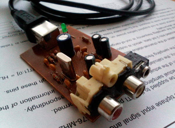
As it turned out, making an external USB sound card is easy and inexpensive. In this article I will tell how I did it.
Background:
A couple of years ago on the Internet on one of the forums I came across a topic about audio DACs. I very much got the idea to solder an audio card (!) And with great interest began to read descriptions of various designs. The complex ones repelled me from repeating them (I had no idea where I would get the I2C “square bus” from my computer or where to get S / PDIF) circuits and expensive (this was the most compelling argument) components. There is very little material on this subject in Russian now ...
After a couple of months, I found a simple design on a PCM2702 chip and, most importantly, with a USB connection to a computer. I was not afraid of the SSOP case of the microcircuit, but I was afraid of the price - more than 500 rubles apiece. Also, I was afraid to spoil such an expensive chip with my inexperience (overheating, statics ... do you think?). I began to look for other solutions. And I came across a design on the PCM2705. This is also a USB codec, but with lower specifications compared to PCM2702.
Chip found in a flea market on one of the forums. I ordered myself and my friend one at a time. I don’t remember exactly at what price, but not more than 150 rubles apiece.
Scheme:
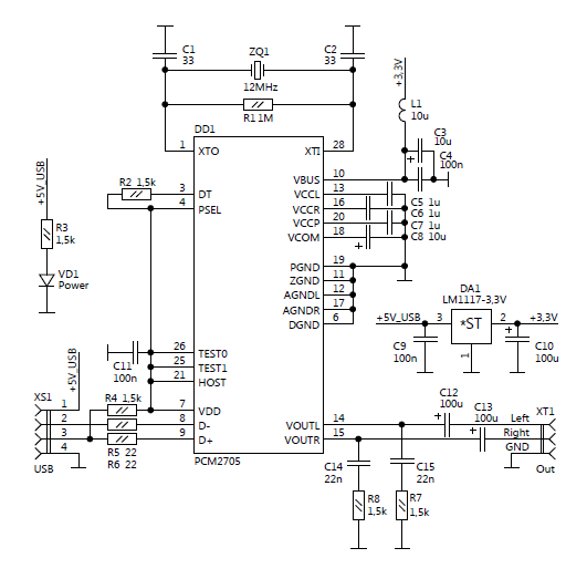
The scheme was repeated almost one-on-one with the original source. And he has an almost clean datasheet there.
Pay:
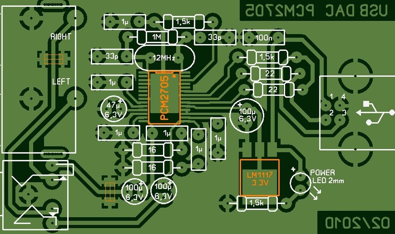
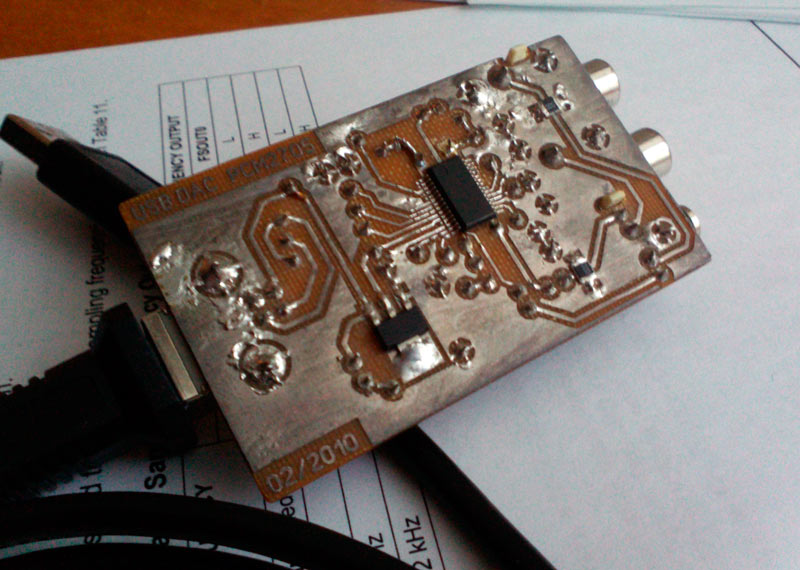
Made his own version of the circuit board. LUT I was already mastered.
First start:
Soldered (I thought I could not solder with a five-millimeter sting, but thanks to DI-HALT for the idea with a microwave ).

With trembling hands, connected to the computer ... OS found a new device. Installed the driver. I connected the headphones - sings! And besides, no worse than the sound built into the laptop. And even better! At least I heard the difference on the bass. I didn’t notice on the HF. But my headphones are not of the best quality.
I also soldered a friend, connected it and ... does not work. I changed the capacitors in the quartz strapping - it did not help, I changed the quartz itself - it worked!
Are you using
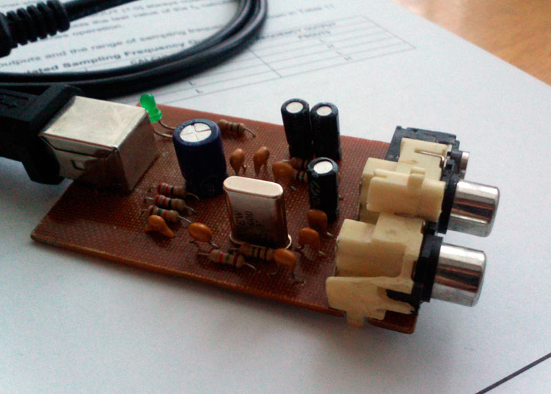
I use it. Sometimes I turn it on when I want a better sound. I would turn it on more often, but it’s inconvenient to use it - the case never did, I drag the laptop back and forth ...
Modernization:
If you use an external power supply with low-noise stabilizers, the sound will be better, because the power on the USB bus contains a lot of different interference. You can also experiment with resistors R7, R8 - put less and increase capacitors C12, C13 - low-frequency transmission will improve.
It was still possible to output S / PDIF, but I had nowhere to stick a track on the printed circuit board, and I did not need it then. And so, it is located on the 5th pin of the microcircuit.
A double-sided, well-designed circuit board would not be detrimental to this design. Since a whole layer of copper will be allocated under the “ground” - this will shorten the path of the return current and reduce the level of interference. At the moment, if next to this DAC lies a mobile phone and receives an incoming call or message, then the familiar “you-you-you-you ... you-you-you-you ... you-you-you- s ..... ".
I can not find PCM2705 ...
Analogs PCM2705 is the PCM2704-2707 line. Briefly about them:
PCM2704: 28-Pin SSOP, Headphone and S / PDIF Output, External ROM Interface
PCM2705: 28-Pin SSOP, Headphone and S / PDIF Output, Serial Programming Interface
PCM2706: 32-Pin TQFP, Headphone and S / PDIF Output, I2S Interface, External ROM Interface
PCM2707: 32-Pin TQFP, Headphone and S / PDIF Output, I2S Interface, Serial Programming Interface
You can use any of them, they are the same in quality.
I attach the datasheet in the archive along with the circuit and the board (open in Sprint Layout 5).