September 5, 2011 at 19:55
Diagnostics of power supply malfunctions using a multimeter
Recently, it was necessary to make a power diagnosis in order to understand why the machine does not start. Unfortunately, there were few suitable articles on this topic on the Internet, so I had to go into the datashit myself.
This article is an extract from my research and I hope to help someone when they have to do the same.
Disclaimer number of times: This article applies only to conventional ATX power supplies, it does not apply to proprietary unit standards (for example, like old DELL or SUN workstations) using a different ATX pinout. Please carefully check the diagram and make sure that your power supply is standard before performing diagnostics in order to avoid harming your computer.
Disclaimer number two: You must understand what you are doing and observe safety precautions, including electrostatic safety (including working in an antistatic wristband). The author is not responsible for damage to the equipment or damage to health due to non-observance or lack of knowledge of the safety precautions and principles of the device.
Let's move on to the theory: the
ATX standard has 2 versions - 1.X and 2.X, with 20 and 24-pin connectors, respectively, the second version has 24-x 4 additional pins, thereby extending the standard connector into 2 sections in this way:
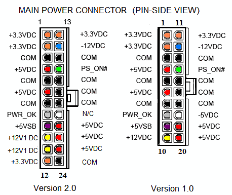
Before we will begin, I will talk about the “rules of the thumb” in relation to faults:
1) A problematic motherboard is easier to replace than repair, this is an extremely complex and multi-layer circuit in which you can only replace a couple of capacitors, but usually this does not solve the problem.
2) If you are not sure what you are doing, then do not do this.
Let's move on to the diagnosis:
you will need a regular multimeter. Thin enough probes are needed so that we can poke into the wire from the back of the connector.
We can’t take anything out of the case. We carry out the diagnostics with the power connector in the motherboard, and the included power supply connected to the network.
Checking the voltage:
If your multimeter does not have an automatic range adjustment function, then set it to measure tens of volts of constant voltage. (Usually indicated by 20 Vdc)
Put the black probe on the ground (GND-pin, COM, see the diagram above) - black wire, for example, pins 15, 16, 17.
Poke the end of the red probe into:
1) Pin 9 (Purple, VSB) - must have a voltage of 5 volt ± 5%. This is a redundant power interface and it always works when the power supply is connected to the network. It is used to power components that should work while the 5 main power channels are unavailable. For example - power control, Wake on LAN, USB devices, tamper control, etc.
If there is no voltage or it is less / more, then this means serious problems with the circuit of the power supply itself.
2) Pin 14 (Green, PS_On) should have a voltage in the region of 3-5 volts. If there is no voltage, then disconnect the power button from the motherboard. If the voltage rises, then the button is to blame.
We still hold the red probe on pin 14 ...
3) We look at the multimeter and press the power button, the voltage should drop to 0, signaling to the power unit that it is necessary to cut the main DC power rails: + 12VDC, + 5VDC, + 3.3VDC, -5VDC and -12 VDC. If there are no changes, then the problem is either in the processor / motherboard, or in the power button. In order to check the power button, pull out its connector from the connector on the motherboard and gently shorten the pins with a light touch of a screwdriver or jumper. You can also try to gently wire PS_On to the ground at the back with a wire. If there are no changes, then most likely something happened with the Metrino board, processor or its socket.
If the suspicion nevertheless falls precisely on the processor, then you can try to replace the processor with a known working one, but do it at your own peril and risk, because if the faulty mother killed him, the same thing can happen to this.
At a voltage of ~ 0 V on PS_On ... (That is, after pressing the button)
4) Check Pin 8 (Gray, Power_OK), it should have a voltage of ~ 3-5V, which will mean that the outputs + 12V + 5V and + 3.3V are at an acceptable level and hold it for a sufficient time, which gives the processor a signal to start. If the voltage is lower than 2.5V, the CPU does not receive a start signal.
In this case, the power supply is to blame.
5) Pressing Restart should cause the voltage on PWR_OK to drop to 0 and quickly rise back.
On some motherboards this will not happen if the manufacturer uses a “soft” reset trigger.
At a voltage of ~ 5V on PWR_OK
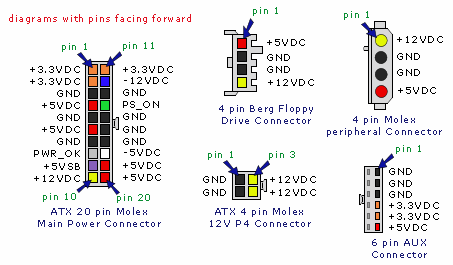
6) We look at the table and check the main parameters of the voltage on the connector and all peripheral connectors:
Test for breakdowns:
DISCONNECT THE COMPUTER FROM THE NETWORK and wait 1 minute until the residual current leaves.
We put a multimeter on the resistance measurement. If your multimeter does not have an automatic adjustment of the range, then put it on the lowest measurement threshold (usually this is a 200 Ω icon). Due to errors, a closed circuit does not always correspond to 0 ohms. Close the probes of the multimeter and see what figure it shows, this will be the zero value for the closed circuit.
Let's check the power supply circuit:
We take out the connector from the motherboard ...
And holding one of the ends of the multimeter on the metal part of the computer case ...
1) Touch the probe of the multimeter to one of the black wires in the connector, and then to the middle pin (ground) of the power plug. The resistance should be zero, if it is not, then the power supply is poorly grounded and should be replaced.
2) Touch the probe to all colored wires in the connector in turn. Values must be greater than zero. A value of 0 or less than 50 ohms indicates a problem in the power supply circuits.
Testing the motherboard for breakdowns:
Remove the processor from the socket ...
We carefully consider the diagram above and, using the power connector as an example, we study which connector ports correspond to what. This is very important, since you can only test the ground (GND, Black wires), otherwise the multimeter current can damage the circuit of the motherboard.
3) We touch one of the multimeter probes to the chassis, and with the other we poke into all the ground connectors (GND, pins 3, 5, 7, 13, 15, 16, 17) and look at the multimeter. Resistance should be zero. If it is not zero, we pull the motherboard out of the case and test it again, only this time one of the probes should touch the metallized ring at the screw hole on which the board is fixed to the back wall of the case. If the resistance value is still non-zero, then something is deeply wrong with the motherboard circuits and most likely it will have to be changed.
For those who are interested and want to get deeper I advise you to read this document:
ATX12V Power Supply Design Guide Guide Version 2.2
This article is an extract from my research and I hope to help someone when they have to do the same.
Disclaimer number of times: This article applies only to conventional ATX power supplies, it does not apply to proprietary unit standards (for example, like old DELL or SUN workstations) using a different ATX pinout. Please carefully check the diagram and make sure that your power supply is standard before performing diagnostics in order to avoid harming your computer.
Disclaimer number two: You must understand what you are doing and observe safety precautions, including electrostatic safety (including working in an antistatic wristband). The author is not responsible for damage to the equipment or damage to health due to non-observance or lack of knowledge of the safety precautions and principles of the device.
Let's move on to the theory: the
ATX standard has 2 versions - 1.X and 2.X, with 20 and 24-pin connectors, respectively, the second version has 24-x 4 additional pins, thereby extending the standard connector into 2 sections in this way:
Before we will begin, I will talk about the “rules of the thumb” in relation to faults:
1) A problematic motherboard is easier to replace than repair, this is an extremely complex and multi-layer circuit in which you can only replace a couple of capacitors, but usually this does not solve the problem.
2) If you are not sure what you are doing, then do not do this.
Let's move on to the diagnosis:
you will need a regular multimeter. Thin enough probes are needed so that we can poke into the wire from the back of the connector.
We can’t take anything out of the case. We carry out the diagnostics with the power connector in the motherboard, and the included power supply connected to the network.
Checking the voltage:
If your multimeter does not have an automatic range adjustment function, then set it to measure tens of volts of constant voltage. (Usually indicated by 20 Vdc)
Put the black probe on the ground (GND-pin, COM, see the diagram above) - black wire, for example, pins 15, 16, 17.
Poke the end of the red probe into:
1) Pin 9 (Purple, VSB) - must have a voltage of 5 volt ± 5%. This is a redundant power interface and it always works when the power supply is connected to the network. It is used to power components that should work while the 5 main power channels are unavailable. For example - power control, Wake on LAN, USB devices, tamper control, etc.
If there is no voltage or it is less / more, then this means serious problems with the circuit of the power supply itself.
2) Pin 14 (Green, PS_On) should have a voltage in the region of 3-5 volts. If there is no voltage, then disconnect the power button from the motherboard. If the voltage rises, then the button is to blame.
We still hold the red probe on pin 14 ...
3) We look at the multimeter and press the power button, the voltage should drop to 0, signaling to the power unit that it is necessary to cut the main DC power rails: + 12VDC, + 5VDC, + 3.3VDC, -5VDC and -12 VDC. If there are no changes, then the problem is either in the processor / motherboard, or in the power button. In order to check the power button, pull out its connector from the connector on the motherboard and gently shorten the pins with a light touch of a screwdriver or jumper. You can also try to gently wire PS_On to the ground at the back with a wire. If there are no changes, then most likely something happened with the Metrino board, processor or its socket.
If the suspicion nevertheless falls precisely on the processor, then you can try to replace the processor with a known working one, but do it at your own peril and risk, because if the faulty mother killed him, the same thing can happen to this.
At a voltage of ~ 0 V on PS_On ... (That is, after pressing the button)
4) Check Pin 8 (Gray, Power_OK), it should have a voltage of ~ 3-5V, which will mean that the outputs + 12V + 5V and + 3.3V are at an acceptable level and hold it for a sufficient time, which gives the processor a signal to start. If the voltage is lower than 2.5V, the CPU does not receive a start signal.
In this case, the power supply is to blame.
5) Pressing Restart should cause the voltage on PWR_OK to drop to 0 and quickly rise back.
On some motherboards this will not happen if the manufacturer uses a “soft” reset trigger.
At a voltage of ~ 5V on PWR_OK
6) We look at the table and check the main parameters of the voltage on the connector and all peripheral connectors:
Test for breakdowns:
DISCONNECT THE COMPUTER FROM THE NETWORK and wait 1 minute until the residual current leaves.
We put a multimeter on the resistance measurement. If your multimeter does not have an automatic adjustment of the range, then put it on the lowest measurement threshold (usually this is a 200 Ω icon). Due to errors, a closed circuit does not always correspond to 0 ohms. Close the probes of the multimeter and see what figure it shows, this will be the zero value for the closed circuit.
Let's check the power supply circuit:
We take out the connector from the motherboard ...
And holding one of the ends of the multimeter on the metal part of the computer case ...
1) Touch the probe of the multimeter to one of the black wires in the connector, and then to the middle pin (ground) of the power plug. The resistance should be zero, if it is not, then the power supply is poorly grounded and should be replaced.
2) Touch the probe to all colored wires in the connector in turn. Values must be greater than zero. A value of 0 or less than 50 ohms indicates a problem in the power supply circuits.
Testing the motherboard for breakdowns:
Remove the processor from the socket ...
We carefully consider the diagram above and, using the power connector as an example, we study which connector ports correspond to what. This is very important, since you can only test the ground (GND, Black wires), otherwise the multimeter current can damage the circuit of the motherboard.
3) We touch one of the multimeter probes to the chassis, and with the other we poke into all the ground connectors (GND, pins 3, 5, 7, 13, 15, 16, 17) and look at the multimeter. Resistance should be zero. If it is not zero, we pull the motherboard out of the case and test it again, only this time one of the probes should touch the metallized ring at the screw hole on which the board is fixed to the back wall of the case. If the resistance value is still non-zero, then something is deeply wrong with the motherboard circuits and most likely it will have to be changed.
For those who are interested and want to get deeper I advise you to read this document:
ATX12V Power Supply Design Guide Guide Version 2.2