STM32F4 debug board in Raspberry Pi form factor
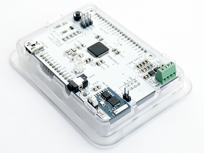 Good afternoon, dear habrovchane! I want to introduce my project to the public - a small debug board based on STM32, but in the Raspberry Pi form factor. It differs from other debugging boards in that it has a geometry compatible with the enclosures from the Raspberry Pi and the availability of an ESP8266 module as a wireless modem. As well as nice additions in the form of a connector for a micro-SD card and a stereo amplifier. To use all this wealth, I developed a high-level library and demonstration program (in C ++ 11). In the article I want to describe in detail both the hardware and software parts of this project.
Who can this project be useful for? Probably, only those who want to solder this board by themselves, since I do not consider any options even for small-scale production. This is purely a hobby. In my opinion, the board covers a fairly wide range of tasks that may arise as part of small home crafts using WiFi and sound.
To begin with, I will try to answer the question why this is all. The main motivators of this project are as follows:
- The choice of STM32 platform is due to purely aesthetic considerations - I like the price / performance ratio, plus a wide range of peripherals, plus a large and convenient development ecosystem from the controller manufacturer (sw4stm, cubeMX, HAL library).
- Of course, there are a lot of debug boards both from the controller manufacturer itself (Discovery, Nucleo) and from third-party manufacturers (for example, Olimex). But to repeat many of them at home in its form factor is problematic, for me at least. In my version, we have a simple two-layer topology and convenient for manual soldering components.
- For their devices you want to have a decent case in order to mask the poor quality of the electronics inside. There are at least two popular platforms for which there is a huge amount of a wide variety of packages: Arduino and Raspberry Pi. The second of them seemed to me more convenient in terms of the location of the clippings under the connectors. Therefore, as a donor for the geometry of the board, I chose it.
- The controller I chose on board has a USB, SDIO, I2S, network. On the other hand, the same interfaces are useful for home hobby platforms. That is why, in addition to the controller with standard strapping, I added a USB connector, an SD card, a sound path (digital-analog converter and amplifier), as well as a wireless module based on the ESP8266.
Scheme and components
It seems to me, it turned out quite nice board with the following characteristics and components:
- STM32F405RG controller : ARM 32-bit Cortex-M4 with a mathematical coprocessor, frequency up to 168 MHz, 1 Mb of flash memory, 196 Kb of RAM.
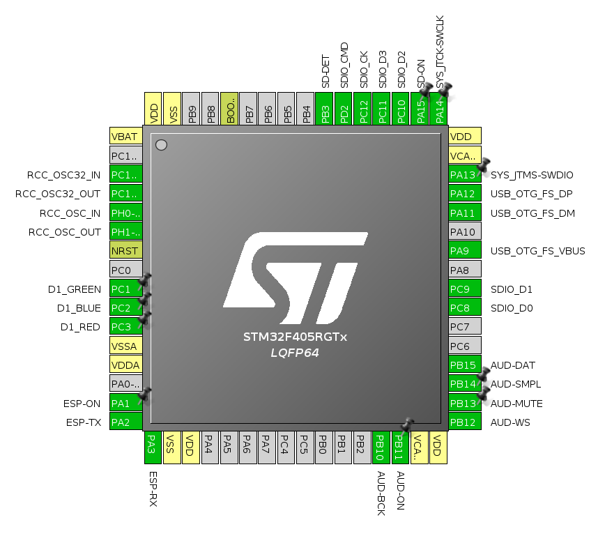

- SWD connector for controller programming (6 pins).
- Reset button to reset.
- Tri-color LED. On the one hand, the three pins of the controller are lost. On the other hand, they would still be lost due to the limited contacts on the GPIO connectors, and such an LED is very useful for debugging.
- High-frequency HSE (16 MHz for core clock) and low-frequency LSE (32.7680 kHz for a real-time clock) quartz.
- GPIO pins with a 2.54 mm pitch are compatible with development boards.
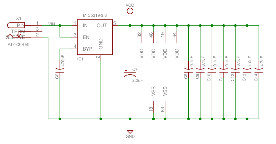
- In place of the 3.5 mm audio jack Raspberry Pi, I placed the power connector 5 volts. At first glance, the decision is controversial. But there are pros. Power supply from the USB connector is optionally present (details below), but for debugging the circuit it is a bad option, since the time before burning the USB port of the computer in this case can be quite short.
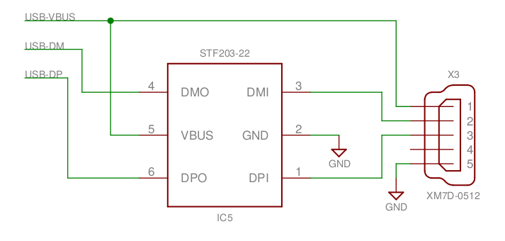
- Mini-usb connector On the one hand, it is connected via the security chip STF203-22.TCT to the USB-OTG port of the controller. On the other hand, the VBUS power pin is connected to the GPIO connector. If you connect it to the + 5V contact, the board will be powered from the USB port.
- Connector micro-SD memory card with strapping: 47 kΩ pull-up resistors, power management transistor ( P-channel MOSFET BSH205 ) and a small green LED on the power line.

The transistor gate is connected to the PA15 pin of the controller. This is the JTDI controller's system contact, which is interesting because in the initial position it is configured as an output with a high level (pull-up) voltage. Since SWD is used instead of JTAG for programming, this contact remains free, and it can be used for other purposes, such as controlling a transistor. This is convenient - when power is applied to the board, the memory card is de-energized, to enable it, you need to apply a low level to the PA15 contact.
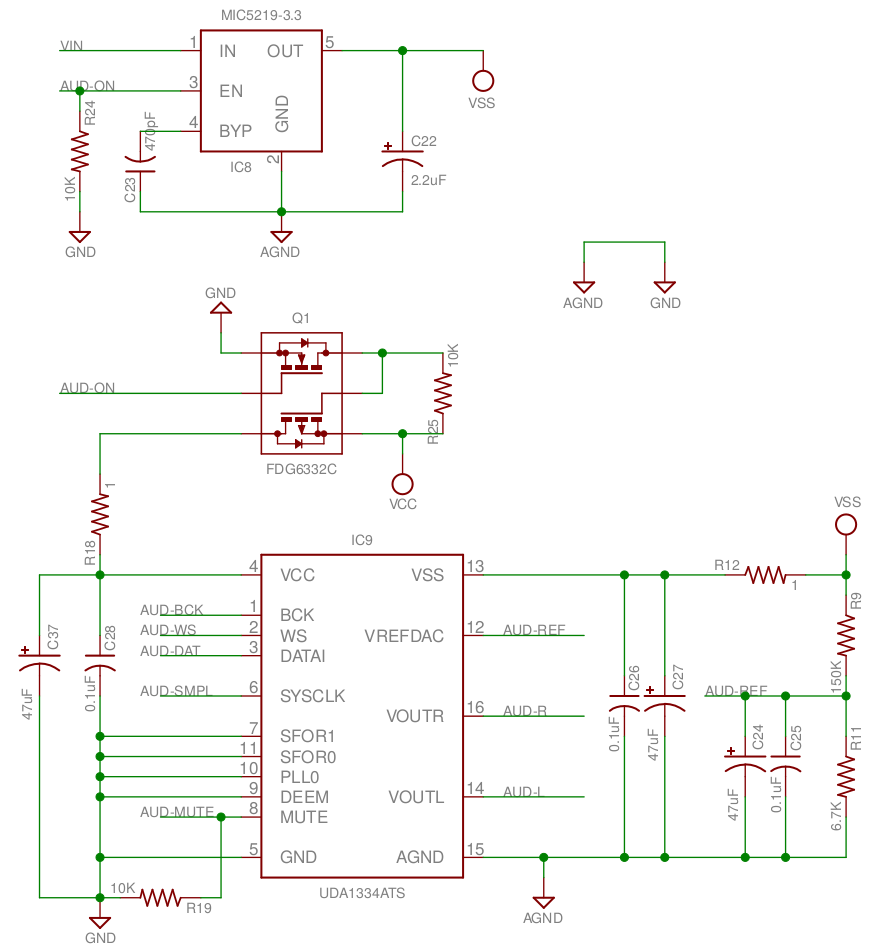
- Digital to analog converter based on UDA1334 . This chip does not need an external clock signal, which facilitates its use. Data is transmitted via the I2S bus. On the other hand, Datasheet recommends using as many as 5 polar capacitors per 47 μF. Size is important in this case. The smallest ones, which turned out to be bought, are tantalic ones with a size of 1411, which are not even very cheap. However, I will write about the price in more detail below. For analog power, its own linear stabilizer is used, the power of the digital part is turned on / off by a dual transistor.
- Two-channel amplifier based on two chips 31AP2005 . Their main advantage is a small number of components of the strapping (only the power filters and the input filter). Audio output - 4 pads with 2.54 mm pitch. For myself, I have not yet decided what is better - such a makeshift version or, like on a malinka, a 3.5 mm plug. As a rule, 3.5 mm is associated with headphones, but in our case we are talking about connecting speakers.

- The last module is an ESP11 strapping with power (power supply, programming connector) as a WiFi modem. The UART pins of the board are connected to the controller and simultaneously output to an external connector (for working with the board directly from the terminal and programming). There is a power switch (permanent external or microcontroller control). There is an additional LED for power indication and a “FLASH” connector for switching the board to programming mode.
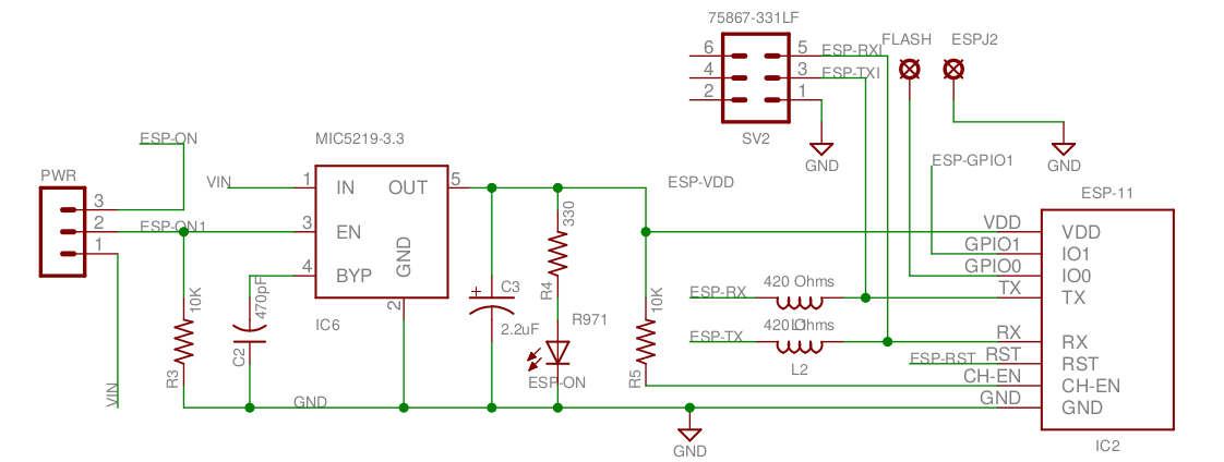
Of course, the ESP8266 itself is a good controller, but it is still inferior to the STM32F4 in terms of both performance and peripherals. Yes, and the size with the price of this module hints that this is just a poured modem unit for its older colleague. The module is controlled by USRT using the text AT protocol.
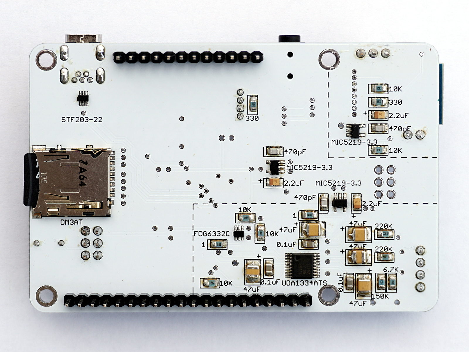
A couple of photos: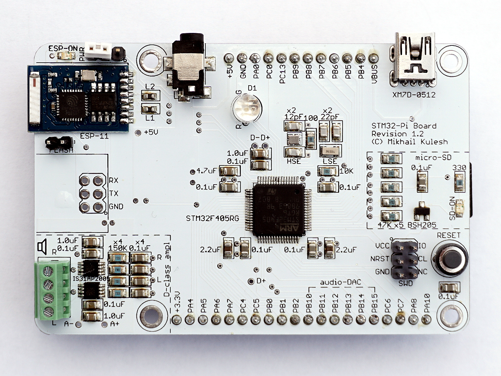
Preparing the ESP11 Module
ESP8266 - a thing known. I am sure that many people are already familiar with it, so a detailed guide will be superfluous here. Due to the schematic features of connecting the ESP11 module to the board, I will give only a brief guide for those who want to change its firmware:
- To work with ESP I will use the esptool utility . Unlike the standard utility from the manufacturer, esptool is platform-independent.
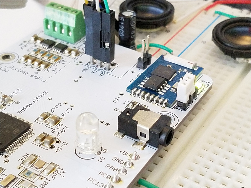
- To begin with, we turn on the external power supply mode with the ESP-PWR jumper (we close the contacts 1 and 2), and connect the module to the computer via any USART-USB adapter. The adapter connects to the pins GRD / RX / TD. Serving food fee:
- Make sure the adapter is recognized by the operating system. In my example, I use an adapter based on FT232, so from the list of devices it should be visible as FT232 Serial (UART) IC:
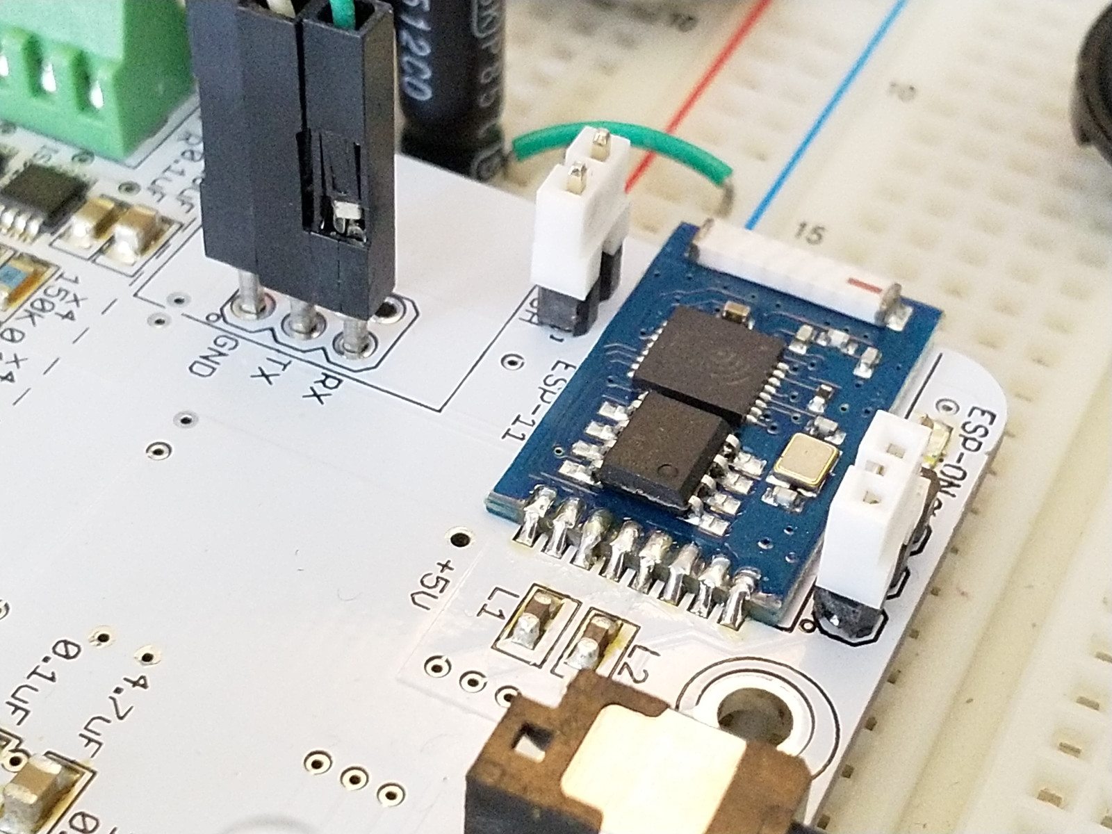
> lsusb ... Bus 001 Device 010: ID 0483:3748 STMicroelectronics ST-LINK/V2 Bus 001 Device 009: ID 0403:6001 Future Technology Devices International, Ltd FT232 Serial (UART) IC ... - The ESP8266s themselves are distinguished by the amount of flash memory. In practice, in the same ESP11 module, I met both 512 KB (4 Mbit) and 1 MB (8 Mbit). So the first thing to check is how much memory is in the module instance used. Turning off the power from the board, and putting the module into programming mode, closing the jumper "FLASH":

- Turn on the power, run esptool with the following parameters
> esptool.py --port /dev/ttyUSB0 flash_id
Connecting....
Detecting chip type... ESP8266
Chip is ESP8266EX
Uploading stub...
Running stub...
Stub running...
Manufacturer: e0
Device: 4014
Detected flash size: 1MB
Hard resetting...- esptool reports that, in this case, we are dealing with a module with 1 MB of memory.
- For the version with 1 MB, you can use the latest firmware, for example, ESP8266 AT Bin V1.6.1 . But it is not suitable for the version with 4 Mbit, for which you need to use something more advanced, for example, this one . The firmware consists of several files, the starting addresses of each file are specified in the official document ESP8266 AT Instruction Set . These start addresses are used as parameters of the esptool utility. For example, for a module with 1 MB, the esptool parameters will look like this (all necessary files need to be extracted from the firmware archive and compiled in the working directory)
> esptool.py --port /dev/ttyUSB0 write_flash 0x00000 boot.bin 0x01000 user1.1024.new.2.bin 0x7E000 blank.bin 0xFB000 blank.bin 0xFC000 esp_init_data_default.bin 0xFE000 blank.bin - We supply power to the board, run esptool with the specified parameters.
- After completion of the script, turn off the power from the board, open the "FLASH" jumper, turn on the power management from the microcontroller. The module is ready for operation.
Software
On github is a test program. She does the following:
- outputs the controller to the maximum frequency (168 MHz)
- activates a real time clock
- activates the SD card and reads the network configuration from it. The FatFS library is used to work with the file system.
- establishes a connection with a given WLAN network
- connects to the specified NTP server and requests the current time from it. Fails the clock.
- monitors the status of several specified ports. If their state has changed, sends a text message to the specified TCP server.
- when you press an external button, it reads the specified * .wav file from the SD card and plays it asynchronously (I2S using the DMA controller).
- Work with ESP11 is also implemented in asynchronous mode (for now without DMA, just on interrupts)
- performs logging through USART1 (pins PB6 / PB7)
- and, of course, the LED flashes.
On Habré there were a lot of articles devoted to programming STM32 at a fairly low level (only register management or CMSIS). For example, from relatively recent: one , two , three. The articles are, of course, very high-quality, but my subjective opinion is that for a one-time development of a product, this approach, perhaps, justifies itself. But for a long hobby project, when you want everything to be beautiful and expandable, this approach is too low-level. One of the reasons for the popularity of Arduino as a software platform, in my opinion, is that the authors of Arduino have gone from such a low level to an object-oriented architecture. Therefore, I decided to go in the same direction and build on a fairly high-level object-oriented layer above the HAL library.
Thus, there are three levels of the program:
- Manufacturer Libraries (HAL, FatFS, in the future USB-OTG) form the foundation
- This foundation is based on my library StmPlusPlus. It includes a set of base classes (such as System, IOPort, IOPin, Timer, RealTimeClock, Usart, Spi, I2S), a set of external device driver classes (such as SdCard, Esp11, DcfReceiver, Dac_MCP49x1, AudioDac_UDA1334, etc.), as well as service classes like asynchronous WAV player.
- On the basis of the StmPlusPlus library, the application itself is being built.
As for the dialect of the language. While I'm a bit old-fashioned, I'm staying in C ++ 11. This standard has several features that are particularly useful for the development of embedded software: enumeration classes (enum class), calling constructors using curly brackets to control the types of parameters passed, static containers of type std :: array. By the way, on Habré there is a wonderful article on this topic.
StmPlusPlus library
The full library code can be viewed on github . Here I will give only a few small examples to show the structure, the idea and the problems generated by this idea.
The first example is a class for periodically polling the status of a pin (for example, a button) and calling the handler when this state changes:
classButton : IOPin
{
public:
    classEventHandler
    {public:
        virtualvoidonButtonPressed(const Button *, uint32_t numOccured)=0;
    };
    Button (PortName name, uint32_t pin, uint32_t pull, const RealTimeClock & _rtc, duration_ms _pressDelay = 50, duration_ms _pressDuration = 300);
    inlinevoidsetHandler(EventHandler * _handler){
        handler = _handler;
    }
    voidperiodic();
private:
    const RealTimeClock & rtc;
    duration_ms pressDelay, pressDuration;
    time_ms pressTime;
    bool currentState;
    uint32_t numOccured;
    EventHandler * handler;
};
The constructor determines all parameters of the button:
Button::Button (PortName name, uint32_t pin, uint32_t pull, const RealTimeClock & _rtc, duration_ms _pressDelay, duration_ms _pressDuration):
    IOPin{name, pin, GPIO_MODE_INPUT, pull, GPIO_SPEED_LOW},
    rtc{_rtc},
    pressDelay{_pressDelay},
    pressDuration{_pressDuration},
    pressTime{INFINITY_TIME},
    currentState{false},
    numOccured{0},
    handler{NULL}
{
    // empty
}
If the handling of such events is not a priority, then the use of interrupts here is clearly unnecessary. Therefore, various pressing scenarios (for example, a single click or hold) are implemented in the periodic procedure, which must be periodically called from the main program code. periodic analyzes the state change and synchronously calls the onButtonPressed virtual handler, which must be implemented in the main program:
void Button::periodic ()
{
    if (handler == NULL)
    {
        return;
    }
    bool newState = (gpioParameters.Pull == GPIO_PULLUP)? !getBit() : getBit();
    if (currentState == newState)
    {
        // state is not changed: check for periodical press eventif (currentState && pressTime != INFINITY_TIME)
        {
            duration_ms d = rtc.getUpTimeMillisec() - pressTime;
            if (d >= pressDuration)
            {
                handler->onButtonPressed(this, numOccured);
                pressTime = rtc.getUpTimeMillisec();
                ++numOccured;
            }
        }
    }
    elseif (!currentState && newState)
    {
        pressTime = rtc.getUpTimeMillisec();
        numOccured = 0;
    }
    else
    {
        duration_ms d = rtc.getUpTimeMillisec() - pressTime;
        if (d < pressDelay)
        {
            // nothing to do
        }
        elseif (numOccured == 0)
        {
            handler->onButtonPressed(this, numOccured);
        }
        pressTime = INFINITY_TIME;
    }
    currentState = newState;
}
The main advantage of this approach is the separation of logic and code for detecting an event from its processing. For time reference, it does not use HAL_GetTick, which, due to its type (uint32_t), is reset by an overflow every 2 ^ 32 milliseconds (every 49 days). I implemented my own RealTimeClock class, which counts out milliseconds from the start of the program, or turning on the controller, like uint64_t, which gives about 5 ^ 8 years.
The second example is working with a hardware interface, which are several in the controller. For example, SPI. From the point of view of the main program, it is very convenient to select only the necessary interface (SPI1 / SPI2 / SPI3), and all other parameters that depend on this interface will be configured by the class constructor.
classSpi
{public:
    constuint32_t TIMEOUT = 5000;
    enumclassDeviceName
    {
        SPI_1 = 0,
        SPI_2 = 1,
        SPI_3 = 2,
    };
    Spi (DeviceName _device,
         IOPort::PortName sckPort, uint32_t sckPin,
         IOPort::PortName misoPort, uint32_t misoPin,
         IOPort::PortName mosiPort, uint32_t mosiPin,
         uint32_t pull = GPIO_NOPULL);
    HAL_StatusTypeDef start(uint32_t direction, uint32_t prescaler, uint32_t dataSize = SPI_DATASIZE_8BIT, uint32_t CLKPhase = SPI_PHASE_1EDGE);
    HAL_StatusTypeDef stop();
    inline HAL_StatusTypeDef writeBuffer(uint8_t *pData, uint16_t pSize){
        return HAL_SPI_Transmit(hspi, pData, pSize, TIMEOUT);
    }
private:
    DeviceName device;
    IOPin sck, miso, mosi;
    SPI_HandleTypeDef *hspi;
    SPI_HandleTypeDef spiParams;
    voidenableClock();
    voiddisableClock();
};
Pin parameters and interface parameters are stored locally in the class. Unfortunately, I chose a not entirely successful implementation, when setting parameters according to a specific interface is implemented directly:
Spi::Spi (DeviceName _device,
          IOPort::PortName sckPort,  uint32_t sckPin,
          IOPort::PortName misoPort, uint32_t misoPin,
          IOPort::PortName mosiPort, uint32_t mosiPin,
          uint32_t pull):
    device(_device),
    sck(sckPort,   sckPin,  GPIO_MODE_AF_PP, pull, GPIO_SPEED_HIGH, false),
    miso(misoPort, misoPin, GPIO_MODE_AF_PP, pull, GPIO_SPEED_HIGH, false),
    mosi(mosiPort, mosiPin, GPIO_MODE_AF_PP, pull, GPIO_SPEED_HIGH, false),
    hspi(NULL)
{
    switch (device)
    {
    case DeviceName::SPI_1:
        #ifdef SPI1
        sck.setAlternate(GPIO_AF5_SPI1);
        miso.setAlternate(GPIO_AF5_SPI1);
        mosi.setAlternate(GPIO_AF5_SPI1);
        spiParams.Instance = SPI1;
        #endifbreak;
    ...
    case DeviceName::SPI_3:
        #ifdef SPI3
        sck.setAlternate(GPIO_AF6_SPI3);
        miso.setAlternate(GPIO_AF6_SPI3);
        mosi.setAlternate(GPIO_AF6_SPI3);
        spiParams.Instance = SPI3;
        #endifbreak;
    }
    spiParams.Init.Mode = SPI_MODE_MASTER;
    spiParams.Init.DataSize = SPI_DATASIZE_8BIT;
    spiParams.Init.CLKPolarity = SPI_POLARITY_HIGH;
    spiParams.Init.CLKPhase = SPI_PHASE_1EDGE;
    spiParams.Init.FirstBit = SPI_FIRSTBIT_MSB;
    spiParams.Init.TIMode = SPI_TIMODE_DISABLE;
    spiParams.Init.CRCCalculation = SPI_CRCCALCULATION_DISABLE;
    spiParams.Init.CRCPolynomial = 7;
    spiParams.Init.NSS = SPI_NSS_SOFT;
}
The same scheme implements the enableClock and disableClock procedures, which is poorly expandable and poorly portable to other controllers. In this case, it is better to use templates, where the template parameter is the HAL interface name (SPI1, SPI2, SPI3), pin parameters (GPIO_AF5_SPI1), and something that controls on / off clocking. There is an interesting article on this topic, although it reviews the AVR controllers, which, however, has no fundamental difference.
The start and end of the transfer are controlled by two methods start / stop:
HAL_StatusTypeDef Spi::start (uint32_t direction, uint32_t prescaler, uint32_t dataSize, uint32_t CLKPhase)
{
    hspi = &spiParams;
    enableClock();
    spiParams.Init.Direction = direction;
    spiParams.Init.BaudRatePrescaler = prescaler;
    spiParams.Init.DataSize = dataSize;
    spiParams.Init.CLKPhase = CLKPhase;
    HAL_StatusTypeDef status = HAL_SPI_Init(hspi);
    if (status != HAL_OK)
    {
        USART_DEBUG("Can not initialize SPI " << (size_t)device << ": " << status);
        return status;
    }
    /* Configure communication direction : 1Line */if (spiParams.Init.Direction == SPI_DIRECTION_1LINE)
    {
        SPI_1LINE_TX(hspi);
    }
    /* Check if the SPI is already enabled */if ((spiParams.Instance->CR1 & SPI_CR1_SPE) != SPI_CR1_SPE)
    {
        /* Enable SPI peripheral */
        __HAL_SPI_ENABLE(hspi);
    }
    USART_DEBUG("Started SPI " << (size_t)device
             << ": BaudRatePrescaler = " << spiParams.Init.BaudRatePrescaler
             << ", DataSize = " << spiParams.Init.DataSize
             << ", CLKPhase = " << spiParams.Init.CLKPhase
             << ", Status = " << status);
    return status;
}
HAL_StatusTypeDef Spi::stop ()
{
    USART_DEBUG("Stopping SPI " << (size_t)device);
    HAL_StatusTypeDef retValue = HAL_SPI_DeInit(&spiParams);
    disableClock();
    hspi = NULL;
    return retValue;
}
Work with the hardware interface using interrupts . The class implements the I2S interface using a DMA controller. I2S (Inter-IC Sound) is a software and hardware add-on over SPI, which itself, for example, selects the clock frequency and controls the channels depending on the audio protocol and bit rate.
In this case, the I2S class is inherited from the “port” class, that is, I2S is a port with special properties. Some data is stored in HAL structures (plus convenience, minus data volume). Some data is transmitted from the main code by reference (for example, the irqPrio structure).
classI2S :public IOPort
{
public:
    const IRQn_Type I2S_IRQ = SPI2_IRQn;
    const IRQn_Type DMA_TX_IRQ = DMA1_Stream4_IRQn;
    I2S (PortName name, uint32_t pin, const InterruptPriority & prio);
    HAL_StatusTypeDef start(uint32_t standard, uint32_t audioFreq, uint32_t dataFormat);
    voidstop();
    inline HAL_StatusTypeDef transmit(uint16_t * pData, uint16_t size){
        return HAL_I2S_Transmit_DMA(&i2s, pData, size);
    }
    inlinevoidprocessI2SInterrupt(){
        HAL_I2S_IRQHandler(&i2s);
    }
    inlinevoidprocessDmaTxInterrupt(){
        HAL_DMA_IRQHandler(&i2sDmaTx);
    }
private:
    I2S_HandleTypeDef i2s;
    DMA_HandleTypeDef i2sDmaTx;
    const InterruptPriority & irqPrio;
};
Its constructor sets all static parameters:
I2S::I2S (PortName name, uint32_t pin, const InterruptPriority & prio):
    IOPort{name, GPIO_MODE_INPUT, GPIO_NOPULL, GPIO_SPEED_FREQ_LOW, pin, false},
    irqPrio{prio}
{
    i2s.Instance = SPI2;
    i2s.Init.Mode = I2S_MODE_MASTER_TX;
    i2s.Init.Standard = I2S_STANDARD_PHILIPS; // will be re-defined at communication start
    i2s.Init.DataFormat = I2S_DATAFORMAT_16B; // will be re-defined at communication start
    i2s.Init.MCLKOutput = I2S_MCLKOUTPUT_DISABLE;
    i2s.Init.AudioFreq = I2S_AUDIOFREQ_44K; // will be re-defined at communication start
    i2s.Init.CPOL = I2S_CPOL_LOW;
    i2s.Init.ClockSource = I2S_CLOCK_PLL;
    i2s.Init.FullDuplexMode = I2S_FULLDUPLEXMODE_DISABLE;
    i2sDmaTx.Instance = DMA1_Stream4;
    i2sDmaTx.Init.Channel = DMA_CHANNEL_0;
    i2sDmaTx.Init.Direction = DMA_MEMORY_TO_PERIPH;
    i2sDmaTx.Init.PeriphInc = DMA_PINC_DISABLE;
    i2sDmaTx.Init.MemInc = DMA_MINC_ENABLE;
    i2sDmaTx.Init.PeriphDataAlignment = DMA_PDATAALIGN_HALFWORD;
    i2sDmaTx.Init.MemDataAlignment = DMA_MDATAALIGN_HALFWORD;
    i2sDmaTx.Init.Mode = DMA_NORMAL;
    i2sDmaTx.Init.Priority = DMA_PRIORITY_LOW;
    i2sDmaTx.Init.FIFOMode = DMA_FIFOMODE_ENABLE;
    i2sDmaTx.Init.FIFOThreshold = DMA_FIFO_THRESHOLD_FULL;
    i2sDmaTx.Init.MemBurst = DMA_PBURST_SINGLE;
    i2sDmaTx.Init.PeriphBurst = DMA_PBURST_SINGLE;
}
The start of data transmission is controlled by the start methods, which are responsible for setting the port parameters, interface clocking, setting interrupts, DMA start, starting the interface itself with the specified transmission parameters.
HAL_StatusTypeDef I2S::start (uint32_t standard, uint32_t audioFreq, uint32_t dataFormat)
{
    i2s.Init.Standard = standard;
    i2s.Init.AudioFreq = audioFreq;
    i2s.Init.DataFormat = dataFormat;
    setMode(GPIO_MODE_AF_PP);
    setAlternate(GPIO_AF5_SPI2);
    __HAL_RCC_SPI2_CLK_ENABLE();
    HAL_StatusTypeDef status = HAL_I2S_Init(&i2s);
    if (status != HAL_OK)
    {
        USART_DEBUG("Can not start I2S: " << status);
        return HAL_ERROR;
    }
    __HAL_RCC_DMA1_CLK_ENABLE();
    __HAL_LINKDMA(&i2s, hdmatx, i2sDmaTx);
    status = HAL_DMA_Init(&i2sDmaTx);
    if (status != HAL_OK)
    {
        USART_DEBUG("Can not initialize I2S DMA/TX channel: " << status);
        return HAL_ERROR;
    }
    HAL_NVIC_SetPriority(I2S_IRQ, irqPrio.first, irqPrio.second);
    HAL_NVIC_EnableIRQ(I2S_IRQ);
    HAL_NVIC_SetPriority(DMA_TX_IRQ, irqPrio.first + 1, irqPrio.second);
    HAL_NVIC_EnableIRQ(DMA_TX_IRQ);
    return HAL_OK;
}
The stop procedure does the opposite:
void I2S::stop ()
{
    HAL_NVIC_DisableIRQ(I2S_IRQ);
    HAL_NVIC_DisableIRQ(DMA_TX_IRQ);
    HAL_DMA_DeInit(&i2sDmaTx);
    __HAL_RCC_DMA1_CLK_DISABLE();
    HAL_I2S_DeInit(&i2s);
    __HAL_RCC_SPI2_CLK_DISABLE();
    setMode(GPIO_MODE_INPUT);
}
Here are some interesting features:
- Used interrupts in this case are defined as static constants. This is a disadvantage to portability to other controllers.
- This code arrangement ensures that the port pins are always in the GPIO_MODE_INPUT state when there is no transmission. This is a plus.
- The priority of interrupts is transmitted from the outside, that is, there is a good opportunity to set the interrupt priority map in one place of the main code. This is also a plus.
- The stop procedure disables DMA1 clocking. In this case, this simplification can have very negative consequences if someone else continues to use DMA1. The problem is solved by creating a centralized register of consumers of such devices, which will be responsible for clocking.
- Another simplification is that the start procedure does not bring the interface back to its original state in the event of an error (this is a minus, but easily fixable). At the same time, errors are logged in more detail, which is a plus.
- The main code should, when using this class, intercept the SPI2_IRQn and DMA1_Stream4_IRQn interrupts and ensure that the corresponding processI2SInterrupt and processDmaTxInterrupt are called.
Main program
The main program is written using the library described above quite simply:
intmain(void){
    HAL_Init();
    IOPort defaultPortA(IOPort::PortName::A, GPIO_MODE_INPUT, GPIO_PULLDOWN);
    IOPort defaultPortB(IOPort::PortName::B, GPIO_MODE_INPUT, GPIO_PULLDOWN);
    IOPort defaultPortC(IOPort::PortName::C, GPIO_MODE_INPUT, GPIO_PULLDOWN);
    // System frequency 168MHz
    System::ClockDiv clkDiv;
    clkDiv.PLLM = 16;
    clkDiv.PLLN = 336;
    clkDiv.PLLP = 2;
    clkDiv.PLLQ = 7;
    clkDiv.AHBCLKDivider = RCC_SYSCLK_DIV1;
    clkDiv.APB1CLKDivider = RCC_HCLK_DIV8;
    clkDiv.APB2CLKDivider = RCC_HCLK_DIV8;
    clkDiv.PLLI2SN = 192;
    clkDiv.PLLI2SR = 2;
    do
    {
        System::setClock(clkDiv, FLASH_LATENCY_3, System::RtcType::RTC_EXT);
    }
    while (System::getMcuFreq() != 168000000L);
    MyApplication app;
    appPtr = &app;
    app.run();
}
Here we initialize the HAL library, all the pins of the controller are configured by default to the input (GPIO_MODE_INPUT / PULLDOWN). Set the frequency of the controller, start the clocking (including the real-time clock from the external quartz). After that, a little Java-style, create an instance of our application and call its run method, which implements all the application logic.
In a separate section, we must define all interrupts used. Since we write in C ++, and interrupts are things from the world of C, they need to be masked accordingly:
extern"C"
{
voidSysTick_Handler(void){
    HAL_IncTick();
    if (appPtr != NULL)
    {
        appPtr->getRtc().onMilliSecondInterrupt();
    }
}
voidDMA2_Stream3_IRQHandler(void){
    Devices::SdCard::getInstance()->processDmaRxInterrupt();
}
voidDMA2_Stream6_IRQHandler(void){
    Devices::SdCard::getInstance()->processDmaTxInterrupt();
}
voidSDIO_IRQHandler(void){
    Devices::SdCard::getInstance()->processSdIOInterrupt();
}
voidSPI2_IRQHandler(void){
    appPtr->getI2S().processI2SInterrupt();
}
voidDMA1_Stream4_IRQHandler(void){
    appPtr->getI2S().processDmaTxInterrupt();
}
voidHAL_I2S_TxCpltCallback(I2S_HandleTypeDef *channel){
    appPtr->processDmaTxCpltCallback(channel);
}
...
}
The MyApplication class declares all the devices used, calls constructors for all these devices, and also implements the necessary event handlers:
classMyApplication :public RealTimeClock::EventHandler, classMyApplication :public RealTimeClock::EventHandler, WavStreamer::EventHandler, Devices::Button::EventHandler
{
public:
    staticconstsize_t INPUT_PINS = 8;  // Number of monitored input pinsprivate:
    UsartLogger log;
    RealTimeClock rtc;
    IOPin ledGreen, ledBlue, ledRed;
    PeriodicalEvent heartbeatEvent;
    IOPin mco;
    // Interrupt priorities
    InterruptPriority irqPrioI2S;
    InterruptPriority irqPrioEsp;
    InterruptPriority irqPrioSd;
    InterruptPriority irqPrioRtc;
    // SD card
    IOPin pinSdPower, pinSdDetect;
    IOPort portSd1, portSd2;
    SdCard sdCard;
    bool sdCardInserted;
    // Configuration
    Config config;
    // ESP
    Esp11 esp;
    EspSender espSender;
    // Input pinsstd::array<IOPin, INPUT_PINS> pins;
    std::array<bool, INPUT_PINS> pinsState;
    // I2S2 Audio
    I2S i2s;
    AudioDac_UDA1334 audioDac;
    WavStreamer streamer;
    Devices::Button playButton;
    ...
That is, in fact, all used devices are declared statically, which potentially leads to an increase in memory usage, but greatly simplifies data access. In the constructor of the MyApplication class, you must call the constructors of all devices, then, by the time the run procedure starts, all the devices used by the microcontroller will be initialized:
    MyApplication::MyApplication () :
            // logginglog(Usart::USART_1, IOPort::B, GPIO_PIN_6, GPIO_PIN_7, 115200),
            // RTC
            rtc(),
            ledGreen(IOPort::C, GPIO_PIN_1, GPIO_MODE_OUTPUT_PP),
            ledBlue(IOPort::C, GPIO_PIN_2, GPIO_MODE_OUTPUT_PP),
            ledRed(IOPort::C, GPIO_PIN_3, GPIO_MODE_OUTPUT_PP),
            heartbeatEvent(rtc, 10, 2),
            mco(IOPort::A, GPIO_PIN_8, GPIO_MODE_AF_PP),
            // Interrupt priorities
            irqPrioI2S(6, 0), // I2S DMA interrupt priority: 7 will be also used
            irqPrioEsp(5, 0),
            irqPrioSd(3, 0), // SD DMA interrupt priority: 4 will be also used
            irqPrioRtc(2, 0),
            // SD card
            pinSdPower(IOPort::A, GPIO_PIN_15, GPIO_MODE_OUTPUT_PP, GPIO_PULLDOWN, GPIO_SPEED_HIGH, true, false),
            pinSdDetect(IOPort::B, GPIO_PIN_3, GPIO_MODE_INPUT, GPIO_PULLUP),
            portSd1(IOPort::C,
                    /* mode     = */GPIO_MODE_OUTPUT_PP,
                    /* pull     = */GPIO_PULLUP,
                    /* speed    = */GPIO_SPEED_FREQ_VERY_HIGH,
                    /* pin      = */GPIO_PIN_8 | GPIO_PIN_9 | GPIO_PIN_10 | GPIO_PIN_11 | GPIO_PIN_12,
                    /* callInit = */false),
            portSd2(IOPort::D,
                    /* mode     = */GPIO_MODE_OUTPUT_PP,
                    /* pull     = */GPIO_PULLUP,
                    /* speed    = */GPIO_SPEED_FREQ_VERY_HIGH,
                    /* pin      = */GPIO_PIN_2,
                    /* callInit = */false),
            sdCard(pinSdDetect, portSd1, portSd2),
            sdCardInserted(false),
            // Configuration
            config(pinSdPower, sdCard, "conf.txt"),
            //ESP
            esp(rtc, Usart::USART_2, IOPort::A, GPIO_PIN_2, GPIO_PIN_3, irqPrioEsp, IOPort::A, GPIO_PIN_1),
            espSender(rtc, esp, ledRed),
            // Input pins
            pins { { IOPin(IOPort::A, GPIO_PIN_4,  GPIO_MODE_INPUT, GPIO_PULLUP),
                     IOPin(IOPort::A, GPIO_PIN_5,  GPIO_MODE_INPUT, GPIO_PULLUP),
                     IOPin(IOPort::A, GPIO_PIN_6,  GPIO_MODE_INPUT, GPIO_PULLUP),
                     IOPin(IOPort::A, GPIO_PIN_7,  GPIO_MODE_INPUT, GPIO_PULLUP),
                     IOPin(IOPort::C, GPIO_PIN_4,  GPIO_MODE_INPUT, GPIO_PULLUP),
                     IOPin(IOPort::C, GPIO_PIN_5,  GPIO_MODE_INPUT, GPIO_PULLUP),
                     IOPin(IOPort::B, GPIO_PIN_0,  GPIO_MODE_INPUT, GPIO_PULLUP),
                     IOPin(IOPort::B, GPIO_PIN_1,  GPIO_MODE_INPUT, GPIO_PULLUP)
            } },
            // I2S2 Audio Configuration// PB10 --> I2S2_CK// PB12 --> I2S2_WS// PB15 --> I2S2_SD
            i2s(IOPort::B, GPIO_PIN_10 | GPIO_PIN_12 | GPIO_PIN_15, irqPrioI2S),
            audioDac(i2s,
                     /* power    = */ IOPort::B, GPIO_PIN_11,
                     /* mute     = */ IOPort::B, GPIO_PIN_13,
                     /* smplFreq = */ IOPort::B, GPIO_PIN_14),
            streamer(sdCard, audioDac),
            playButton(IOPort::B, GPIO_PIN_2, GPIO_PULLUP, rtc)
    {
        mco.activateClockOutput(RCC_MCO1SOURCE_PLLCLK, RCC_MCODIV_5);
    }
As an example, the event handler for pressing the button, by which the WAV file starts playing / stops:
virtualvoid MyApplication::onButtonPressed (const Devices::Button * b, uint32_t numOccured)
    {
        if (b == &playButton)
        {
            USART_DEBUG("play button pressed: " << numOccured);
            if (streamer.isActive())
            {
                USART_DEBUG("    Stopping WAV");
                streamer.stop();
            }
            else
            {
                USART_DEBUG("    Starting WAV");
                streamer.start(AudioDac_UDA1334::SourceType:: STREAM, config.getWavFile());
            }
        }
    }
And finally, the main run method finishes device configuration (for example, sets MyApplication as an event handler), and starts an infinite loop where it periodically refers to those devices that require periodic attention:
void MyApplication::run ()
    {
        log.initInstance();
        USART_DEBUG("Oscillator frequency: "
                << System::getExternalOscillatorFreq() << ", MCU frequency: " << System::getMcuFreq());
        HAL_StatusTypeDef status = HAL_TIMEOUT;
        do
        {
            status = rtc.start(8 * 2047 + 7, RTC_WAKEUPCLOCK_RTCCLK_DIV2, irqPrioRtc, this);
            USART_DEBUG("RTC start status: " << status);
        }
        while (status != HAL_OK);
        sdCard.setIrqPrio(irqPrioSd);
        sdCard.initInstance();
        if (sdCard.isCardInserted())
        {
            updateSdCardState();
        }
        USART_DEBUG("Input pins: " << pins.size());
        pinsState.fill(true);
        USART_DEBUG("Pin state: " << fillMessage());
        esp.assignSendLed(&ledGreen);
        streamer.stop();
        streamer.setHandler(this);
        streamer.setVolume(1.0);
        playButton.setHandler(this);
        bool reportState = false;
        while (true)
        {
            updateSdCardState();
            playButton.periodic();
            streamer.periodic();
            if (isInputPinsChanged())
            {
                USART_DEBUG("Input pins change detected");
                ledBlue.putBit(true);
                reportState = true;
            }
            espSender.periodic();
            if (espSender.isOutputMessageSent())
            {
                if (reportState)
                {
                    espSender.sendMessage(config, "TCP", config.getServerIp(), config.getServerPort(), fillMessage());
                    reportState = false;
                }
                if (!reportState)
                {
                    ledBlue.putBit(false);
                }
            }
            if (heartbeatEvent.isOccured())
            {
                ledGreen.putBit(heartbeatEvent.occurance() == 1);
            }
        }
    }
Some experiments
An interesting fact - the microcontroller can be partially overclocked. Its maximum frequency is 168 MHz. However, playing the clocking parameters, I managed to run it at 172 MHz and 180 MHz, that is, the clocking initialization with such a frequency is performed without errors, and this frequency is visible on the oscilloscope, if it is connected to the pin of the MCO output clock signal. But at the same time, the controller hangs, if you use USART or I2S, which, perhaps, is just a software problem at the HAL level.
Price
This is the most sensitive issue in all this work. On github there is a list of all components of the board. To get at least some figure, I meticulously collected the prices of all the components from this list from the Mouser website (do not count for advertising). It’s impossible to look at the resulting figure of 37 Euro without tears. To it you need to add the cost of manufacturing the board and time for soldering. That is, compared to the mass demonstration boards from STM or Olimex, my board was very expensive.
Problems and Prospects
Surely I implemented many things in a very inefficient way. In the current version, I myself see the problems that need to be fixed:
- The ground of the high-frequency quartz earth is diluted with an error (brought to the main earth). Instead, it would be possible to connect it with the microcontroller's earthen foot, but it just didn't work out to get close to it on a double-layer board. The comments have already suggested a possible solution: lower the frequency of quartz to 4 or 8 MHz. The required core frequency is still obtained after PLL, and a lower frequency of quartz would allow leveling out the wiring problems.
- Experiments with the oscilloscope showed that the power line of the controller is very noisy. The additional input filtering capacitor at 47 μF improves the situation. Probably need to add it.
- The location of the SWD connector for programming the controller is not very convenient. If you put some expansion board on top, you won't get to it. It is necessary to transfer to another place.
- The arrangement of the tricolor LED is also unfortunate. I want to replace it with SMD LED, put it on the edge of the board. The comments also prompted to add 3 resistors to each of the anodes of the LED separately.
Documentation
The project is published on github under the GPL v3 license:
Thanks for attention!