June 14, 2011 at 19:15
Finalization of Chinese speakers (SVEN SPS-678)
Hi% username%. Today I will tell you how to upgrade your computer acoustics a bit. I must say right away that this guide does not aim to make B&W out of your acoustics, but only to reasonably improve the sound with minimal time and money.
So, we have such columns here:

What is the problem of such devices ?? And the fact that the Chinese are saving completely on everything, which we can see by looking at the circuit diagram of the amplifier found in the vastness of the network: The

speakers have all almost the same circuit, so you,% username%, should have no trouble figuring out.
Here you can download in full size.
Having opened, you should see something like this:

What we need:
Let's start with the power supply. Transformer 2 * 13V 1.2A. But how so,% username% !! ?? Indeed, on the box it is written that the speakers should each produce 18 watts of power, and with such a transformer it turns out only P = U * I = 15.6 W for 2 channels !!! But here everything is actually a little more complicated. Such a calculation will be true for a sinusoidal signal, but a real musical signal is much more complicated, it reaches its maximums quite rarely. If we take the average signal level, then compared with the sine, it is several times smaller. You can find comprehensive information in this article.
So using the program you can make sure that our transformer almost fits into the requirements.
Further, we have a diode bridge D1-D4 from diodes 1N4007 . We replace 1-ampere diodes with Schottky diodes, since the direct voltage drop on them is less than on silicon diodes. I set 1N5819 . Any diodes are suitable, if only the current and reverse voltage fit the circuit parameters.
On average, the voltage drop on silicon diodes is 0.5-0.6V, on my instances the voltage drop was only 150 mV.
And do not forget to grease the soldering flux very thickly, then the solder will gather in beautiful shiny balls around the terminals. If you spread a little, it will be bad to pester contacts and spread out in all directions.
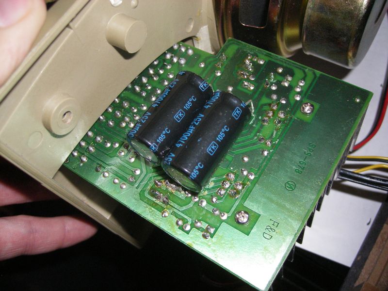
Here, the masters from China also decided to save money and put only 3300 microfarads in the shoulder. Not enough, it is necessary to increase, only without fanaticism !!! The more capacitance you put, the greater the current goes through the diodes at the time of charging the capacitors and they can not withstand.
I put an additional 4700 microfarads per shoulder, leaving my family.
Everything is with the power supply.
At the entrance are electrolytes (C9, C10) - a mess, since it works on alternating current without bias, which is not at all good. In the datasheet on the microcircuit there is a capacitor with a capacity of 1 μF, though it is also an electrolyte.
We go to the store and buy our domestic film K73-17 with a capacity of 1 microfarad and put it on. Since it is much more electrolyte, it is better to put heat shrink on your feet so that nothing closes. Solder:

If you can call it an electrolytic capacitor of 4.7 microfarads.
There are two options:
We have a capacitor on Twitter, which cuts the lower frequencies (1st order filter), and the entire range goes to the woofer. It would be possible to make a crossover, but the quality / labor ratio would have turned out not in favor of quality. Therefore, we choose the first option. And again, we put the film capacitor K73-17 4.7 uF:

Do not forget to perform a similar operation in the second column.
It also does not shine with skillful design, so if you want, you can turn it off by connecting the wires from the input immediately to the volume control (R9, R10). But for now, I decided to leave.
Everything is very subjective here. But my look has become noticeably denser.
But there are objective parameters:
So, with minimal financial investment and time, you can slightly improve the sound of your speaker system.
So, we have such columns here:
What is the problem of such devices ?? And the fact that the Chinese are saving completely on everything, which we can see by looking at the circuit diagram of the amplifier found in the vastness of the network: The
speakers have all almost the same circuit, so you,% username%, should have no trouble figuring out.
Here you can download in full size.
Having opened, you should see something like this:
What we need:
- soldering iron
- solder
- flux
- heat-shrink tubing
- Details to taste :)
Power Supply
Let's start with the power supply. Transformer 2 * 13V 1.2A. But how so,% username% !! ?? Indeed, on the box it is written that the speakers should each produce 18 watts of power, and with such a transformer it turns out only P = U * I = 15.6 W for 2 channels !!! But here everything is actually a little more complicated. Such a calculation will be true for a sinusoidal signal, but a real musical signal is much more complicated, it reaches its maximums quite rarely. If we take the average signal level, then compared with the sine, it is several times smaller. You can find comprehensive information in this article.
So using the program you can make sure that our transformer almost fits into the requirements.
Rectifier.
Further, we have a diode bridge D1-D4 from diodes 1N4007 . We replace 1-ampere diodes with Schottky diodes, since the direct voltage drop on them is less than on silicon diodes. I set 1N5819 . Any diodes are suitable, if only the current and reverse voltage fit the circuit parameters.
On average, the voltage drop on silicon diodes is 0.5-0.6V, on my instances the voltage drop was only 150 mV.
And do not forget to grease the soldering flux very thickly, then the solder will gather in beautiful shiny balls around the terminals. If you spread a little, it will be bad to pester contacts and spread out in all directions.
Filter capacitors
Here, the masters from China also decided to save money and put only 3300 microfarads in the shoulder. Not enough, it is necessary to increase, only without fanaticism !!! The more capacitance you put, the greater the current goes through the diodes at the time of charging the capacitors and they can not withstand.
I put an additional 4700 microfarads per shoulder, leaving my family.
Everything is with the power supply.
Amplifier.
At the entrance are electrolytes (C9, C10) - a mess, since it works on alternating current without bias, which is not at all good. In the datasheet on the microcircuit there is a capacitor with a capacity of 1 μF, though it is also an electrolyte.
We go to the store and buy our domestic film K73-17 with a capacity of 1 microfarad and put it on. Since it is much more electrolyte, it is better to put heat shrink on your feet so that nothing closes. Solder:
Crossover
If you can call it an electrolytic capacitor of 4.7 microfarads.
There are two options:
- just put the film
- we are thinking a new crossover
We have a capacitor on Twitter, which cuts the lower frequencies (1st order filter), and the entire range goes to the woofer. It would be possible to make a crossover, but the quality / labor ratio would have turned out not in favor of quality. Therefore, we choose the first option. And again, we put the film capacitor K73-17 4.7 uF:
Do not forget to perform a similar operation in the second column.
Timbral block
It also does not shine with skillful design, so if you want, you can turn it off by connecting the wires from the input immediately to the volume control (R9, R10). But for now, I decided to leave.
Sound
Everything is very subjective here. But my look has become noticeably denser.
But there are objective parameters:
- an increase in the capacities in the BP filter gives less drawdowns and at high volume there will be no feeling that the sound is failing.
- the use of Schottky diodes slightly increases the supply voltage, allowing you to overclock the microcircuit to more power (22V datasheet voltage)
- film capacitors introduce many times less distortion than electrolytic
In custody:
So, with minimal financial investment and time, you can slightly improve the sound of your speaker system.