Moving Light Tracker
Today I decided to write about one interesting project that I was engaged in in my free time from studies.
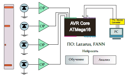
The essence of the device is simple - there is a matrix of photodiodes (in this case 4, but more can be) that registers light from some source that can move. Naturally, the amount of light incident on each photodiode individually is different.
The device must determine the spatial location of the light source that is moving. This is the main goal. That is, it is necessary to programmatically solve the problem of multidimensional correlation between the intensity vector and the location vector of the light source.
The general scheme is shown in the figure above. In our case, only 4 photodiodes. The signal from the photodiodes is amplified and fed to the ATMega16 microcontroller. The microcontroller generates a data packet and sends it with a frequency of 1 Hz via USART (COM port). From the computer side, a program written in Lazarus (FreePascal) runs, which reads data from the port and analyzes using a free neural network library, then gives the result of the location of the light source.
This was a brief description, and now details.
Here is a simple diagram of connecting a photodiode to an operational amplifier, a small current to voltage converter circuit, can be found in any book on circuitry.
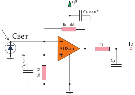
Incident light causes a photocurrent, the circuit is linear (until saturated), in contrast to the circuit with an offset. The current almost does not flow into the inverting input, and therefore the output voltage is defined as U = I * R1.
A very good article on photodiodes and amplifiers was written by an employee of Texas Instruments Philip CD HOBBS “Amplifiers for Photodiodes on Operational Amplifiers”. I recommend to all interested.
I used high-speed PIN photodiodes, BPW34. They do not have a very wide viewing angle - what was at hand, then used it. Almost any photodiode is suitable here, a matter of taste.
Red line requires operational amplifier AD820. A field effect transistor amplifier (FET) has an advantage over bipolar low leakage currents, so this is very important in current-voltage converter circuits. The amplifier also has a Rail-to-Rail output, that is, the magnitude of the output voltage can approach very close to the power buses.
I recommend using a low-pass filter after the amplifier output (low-pass filter), and selecting the desired cut-off frequency so that there is less noise.
As I wrote above, the microcontroller is needed in order to digitize the signals and transmit them to the PC port.
It uses the oldest MAX232ACPE converter for COM port. Now I use controllers with hardware USB, but a year ago, the MAX232 circuit seemed very cool to me, and I was very happy when I finally figured it out.
Those who do not have a board with COM ports will either have to assemble it themselves on the FT232RL or buy a USB-USART converter, which are now in bulk on the Internet.

First of all, you need to organize a stable power supply for the microcontroller (MK). For nutrition, always put as close as possible to the legs of the MK ceramic capacitor with a capacity of 0.1 uF. The figure is between VCC and GND.
Then you need to take care of the clock signal.
Here stands a quartz resonator at 8MHz (believe me, when I started, I also thought that it was so small). To increase stability, picofarad capacitors are installed as shown in the diagram. Each frequency needs its own rating, for details, see the datasheet, the official passport-documentation for each IC (integrated circuit).
In order for the MK to work without accidental discharges, it is necessary to connect a Vcc to RESET via a pull-up resistor.
The analog inputs of PA0..7 are the ports where we feed signals from amplifiers.
We'll take Vcc as the reference voltage for the ADC, and that's not so tricky at all.
RX, TX ports are used to send and receive data.
TTL logic and RS232 logic are very different, and can not work directly, so we use a converter, the connection diagram is shown on the left. All capacitors shown in the converter wiring diagram are ceramic and have a nominal value of 0.1 uF.
I did this project on the Lazarus IDE, the FreePascal compiler, in the process of writing I used several components and libraries.
To work with neural networks, I chose the free FANN library. I think that most people know how neural network algorithms work, but just in case, I will repeat on my example.
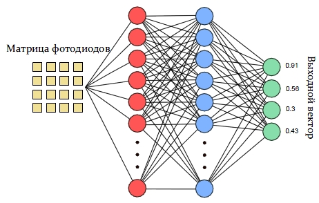
Here, the neural network must first learn with the teacher.
The meaning of training is that the network must adjust the coefficients of the matrix matrices in such a way as to minimize the difference between the output vector and the training vector.
Each task is unique in a certain sense, and therefore there is no theory that would say how many neurons are enough to solve the problem, which transfer function should be used, and so on.
That's all,
the next time I find the time - I’ll write a sequel in which such parts as:
The next part will be fully software.
The essence of the device is simple - there is a matrix of photodiodes (in this case 4, but more can be) that registers light from some source that can move. Naturally, the amount of light incident on each photodiode individually is different.
The device must determine the spatial location of the light source that is moving. This is the main goal. That is, it is necessary to programmatically solve the problem of multidimensional correlation between the intensity vector and the location vector of the light source.
The general scheme is shown in the figure above. In our case, only 4 photodiodes. The signal from the photodiodes is amplified and fed to the ATMega16 microcontroller. The microcontroller generates a data packet and sends it with a frequency of 1 Hz via USART (COM port). From the computer side, a program written in Lazarus (FreePascal) runs, which reads data from the port and analyzes using a free neural network library, then gives the result of the location of the light source.
This was a brief description, and now details.
1) Connecting photodiodes
Here is a simple diagram of connecting a photodiode to an operational amplifier, a small current to voltage converter circuit, can be found in any book on circuitry.
Incident light causes a photocurrent, the circuit is linear (until saturated), in contrast to the circuit with an offset. The current almost does not flow into the inverting input, and therefore the output voltage is defined as U = I * R1.
A very good article on photodiodes and amplifiers was written by an employee of Texas Instruments Philip CD HOBBS “Amplifiers for Photodiodes on Operational Amplifiers”. I recommend to all interested.
I used high-speed PIN photodiodes, BPW34. They do not have a very wide viewing angle - what was at hand, then used it. Almost any photodiode is suitable here, a matter of taste.
Red line requires operational amplifier AD820. A field effect transistor amplifier (FET) has an advantage over bipolar low leakage currents, so this is very important in current-voltage converter circuits. The amplifier also has a Rail-to-Rail output, that is, the magnitude of the output voltage can approach very close to the power buses.
I recommend using a low-pass filter after the amplifier output (low-pass filter), and selecting the desired cut-off frequency so that there is less noise.
2) ATMEGA16 microcontroller
As I wrote above, the microcontroller is needed in order to digitize the signals and transmit them to the PC port.
It uses the oldest MAX232ACPE converter for COM port. Now I use controllers with hardware USB, but a year ago, the MAX232 circuit seemed very cool to me, and I was very happy when I finally figured it out.
Those who do not have a board with COM ports will either have to assemble it themselves on the FT232RL or buy a USB-USART converter, which are now in bulk on the Internet.
First of all, you need to organize a stable power supply for the microcontroller (MK). For nutrition, always put as close as possible to the legs of the MK ceramic capacitor with a capacity of 0.1 uF. The figure is between VCC and GND.
Then you need to take care of the clock signal.
Here stands a quartz resonator at 8MHz (believe me, when I started, I also thought that it was so small). To increase stability, picofarad capacitors are installed as shown in the diagram. Each frequency needs its own rating, for details, see the datasheet, the official passport-documentation for each IC (integrated circuit).
In order for the MK to work without accidental discharges, it is necessary to connect a Vcc to RESET via a pull-up resistor.
The analog inputs of PA0..7 are the ports where we feed signals from amplifiers.
We'll take Vcc as the reference voltage for the ADC, and that's not so tricky at all.
RX, TX ports are used to send and receive data.
TTL logic and RS232 logic are very different, and can not work directly, so we use a converter, the connection diagram is shown on the left. All capacitors shown in the converter wiring diagram are ceramic and have a nominal value of 0.1 uF.
3) Development environment and libraries used
I did this project on the Lazarus IDE, the FreePascal compiler, in the process of writing I used several components and libraries.
- Library for working with COM port CportLib
- Famous FANN Library
To work with neural networks, I chose the free FANN library. I think that most people know how neural network algorithms work, but just in case, I will repeat on my example.
Here, the neural network must first learn with the teacher.
The meaning of training is that the network must adjust the coefficients of the matrix matrices in such a way as to minimize the difference between the output vector and the training vector.
Each task is unique in a certain sense, and therefore there is no theory that would say how many neurons are enough to solve the problem, which transfer function should be used, and so on.
That's all,
the next time I find the time - I’ll write a sequel in which such parts as:
- Receive data from MK
- Neural network training
- Data analysis using a neural network
The next part will be fully software.