Imitation of water levitation on Arduino

Good evening! In this publication I will talk about my home-made, which I had planned for a long time. But realized just now.
I first saw this effect in childhood. I was asked to help, hold and shine a car strobe on the flywheel of a car engine. The motor was started and after that I saw on a rotating flywheel, an almost non-moving notch that stood in one place, and the flywheel at the same time rotated. Then the idea was born to make a fan and stop it with a strobe. After a while he realized the idea, on the IFK-120 lamp, the KU202 thyristor with a strapping, played and threw it into the far corner, but about 6 years ago I saw a Japanese video with water levitation. So the idea was born to repeat this trick with levitation drops. Long did not reach the realization of the hand and finally, the dream came true ...
Watch a video of what I did:
How it works
In YouTube there are several videos in which they are trying to dissect water into droplets flowing from a silicone hose using an audio column or a dynamic head. But in this way there are several drawbacks.
1 - the bulkiness of the structure (column, amplifier, frequency generator, strobe)
2 - the subwoofer cannot reproduce the square wave, because of its mechanical structure and at the output it turns out something like a sinusoid. As a result, water is not dissected into drops, but wriggles like a snake.
3 - The frequency generator each time you have to adjust to the frequency of the strobe. The frequency will float away.
In my design, everything is simple and cheap. This design can be repeated by anyone, at home.
It works like this:
The stroboscope and an electromagnet from the automobile relay, work at one frequency. The electromagnet breaks the flow of water into droplets, and the stroboscope illuminates these droplets, at some point. Since the drops fall with a frequency equal to the stroboscope, the effect of droplets hanging in the air is obtained.
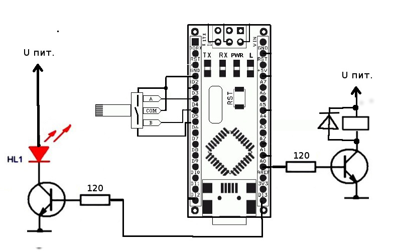
Scheme
I had KT972 transistors on hand, so I set them up. You can put any other transistors designed for a voltage of at least 30V and a current of at least 2A. Resistors in the bases of transistors limit the current to 40mA, so as not to damage the controller output. I used the LED element from an old faulty LED lamp. To reduce the supply voltage of the element to 24 V. I divided the element into two parts, cutting one track and paralleling these two arrays of LEDs. Since the power supply of the LED element is carried out by short pulses, and the supply voltage is equal to the voltage drop on the LEDs, I did not limit the current. A diode parallel to the electromagnet protects against negative emissions of an electromagnetic coil. You can put a diode from the same disassembled LED lamp. Electromagnet made from automotive relays. I had already broken the relay, so I had to use it for what it is. If I had a working relay, I would first try to connect a Chinese stick to anchor the relay. To ensure the gap between the permanent magnet and the electromagnet, you can put a piece of foam rubber between them, or move the stick with the magnet to the side. As I did.
Components used in the diagram:
Arduino nano - 1 pc.
Encoder - 1 pc.
Development board - 1 pc.
Old LED lamp - 1 pc.
Transistor KT972 - 2 pcs.
Automotive relay - 1 pc.
120 ohm resistor - 2pcs.
Details on the Arduino code
I use Arduino Nano because I have a lot of them and they fit perfectly on the breadboard. But you can use absolutely any Arduino controller and even Digispark. The encoder uses the INT1 interrupt. If you rotate the encoder without pressing, then the frequency of the stroboscope flashes and the frequency of the electromagnet are adjusted in increments of 0.1 Hz. If you rotate with a click, then the duration of the LED flashes is regulated, for photographers this is called the exposure time. In this case, the frequency does not change. Control of the LED element, for convenience of debugging, I connected to D13, but you can change all the connection pins for any other. Only you can not change the pin D3 (INT1) encoder.
Sketch for Arduino
// Выводы ЭНКОДЕРА#define CLK 3  // Clock Подключаем к INT1, нельзя переназначать#define DT 4  // второй вывод энкодера#define SW 5  // switch кнопка энкодера#define led_pin 13       // подключен светодиод#define coil_pin A0      // электромагнит#define Min 1 // минимальное значение #define Max 20000 //максимальное значение#define step_freq 1       // шаг изменения частоты плавно 0,1Гц#define step_freq_rough 10   // шаг изменения частоты грубо 1Гц #define step_timelght 100 // шаг приращивания в мкс
volatile int freq = 250; // частота в Гц умноженная на 10, для более плавной настройки
volatile uint32_t paus, time_light=2000; // время свечения светодиода в мкс по умолчанию
uint32_t oldcount;
boolean DT_last; // последнее состояние энкодера
void setup()
{
  pinMode(CLK,INPUT_PULLUP); // Clock Подключаем к INT1, нельзя переназначать
  pinMode(DT, INPUT_PULLUP); // второй вывод энкодера
  pinMode(SW, INPUT_PULLUP); // кнопка энкодера
  pinMode(led_pin, OUTPUT);    // управление симистором
  pinMode(coil_pin, OUTPUT);
  attachInterrupt(1, encoderTick, CHANGE); // прерывания от Энкодера
  DT_last = digitalRead(CLK);         // считываем положение CLK
  Serial.begin(115200);           // для отладки
}
void loop()
{
    paus=5000000/freq;
    digitalWrite(coil_pin, 1);
    digitalWrite(led_pin, 1);
    oldcount = micros();
    while( (micros() - oldcount) < time_light){}   // длительность импульса выдержки
    digitalWrite(led_pin, 0);
    while( (micros() - oldcount) < paus){}  // положительный полупериод
    digitalWrite(coil_pin, 0);
    oldcount = micros();
    while( (micros() - oldcount) < paus){} //отрицательный полупериод
}
//********************обработчики прерываний Энкодера*******************************
void encoderTick()
{
  uint8_t DT_now = digitalRead(CLK);       // считываем текущее положение CLKif (DT_now != DT_last && digitalRead(SW))   // если предыдущее и текущее положение не равны, значит был поворот
  {
    if (digitalRead(DT) != DT_now)    // если DT не равен CLK, значит вращение по часовой стрелке
    {
      if( freq < Max ) freq += step_freq;    // прибавить
    } else {                                   // если DT равен CLK, значит вращение против часовойif( freq > Min ) freq -= step_freq;  // убавить
            }
  } elseif (DT_now != DT_last && !digitalRead(SW)) //если нажата кнопка и было вращение
          {
           if (digitalRead(DT) != DT_now)         // если DT не равен CLK, значит вращение по часовой стрелке
            {
              if( time_light < paus ) { time_light += step_timelght; } // убавить длительность
            } elseif( time_light > 0 ) time_light -= step_timelght;    // прибавить длительность импульса выдержки/
          }
  DT_last = DT_now;                   // сохранить положение CLK для следующей проверки
}
Levitron setting
The basic setting is reduced to adjusting the flow of water. You need to adjust the flow rate of water so that the electromagnet can consistently break the flow of water into droplets. I think that it is very simple and you will immediately see visually where the golden mean is. Also adjust the frequency of the strobe flashes to be more comfortable for your eyes. The frequency of the flashes affects
the distance between the drops, and if the drops begin to break without synchronization, then re-arrange the flow of water. If you want to shoot video on the camera, then you need to adjust the stroboscope to the frequency of the camera, so that the camera does not have flicker.
What's next?
I plan to buy a pulse pump and, on its basis, make a levitating rain from a shower watering can. So there will be another small article and a video on the topic of "Water Levitation"
Subscribe to not miss a new article and video.
There will be questions ask, do not hesitate.
I will answer them with pleasure