How to become a magician (part 2). Technical backstage
Geektimes, hello! As promised, this is a continuation of the last article about our little world of magic. Today I will talk about the backstage magical quests, what decisions were made and how we came to the conclusion that the quest has just such a scenario and look.
Because before the construction of the quest, I was interested in electronics, in particular, programming AVR-microcontrollers in C, it was decided to try to maximize this potential, which would give the opportunity to add a maximum of interactive, interest and excitement to the quest! In addition, I really did not want to do the quest similar to dozens of others (working at that time in our city).
While thinking about the new scenario, we clearly decided that we would have neither locks, nor keys, nor standard tasks, in general, we turn on the electronics to the maximum of our capabilities!
Let's take a closer look at the technical part, and now I will tell you how to make electronics as collective as simple as possible .
general review
We will omit the initial implementation of the quest (maybe I will tell about it later), and concentrate on the moment of completion (after which the quest has the final look).
After we discussed our new vision of the quest, I realized that the strength of one microcontroller is not enough and you need to connect a computer, combining all the devices into a single system. To understand the integrity of the picture, an outline of all devices and their interactions was drawn up:
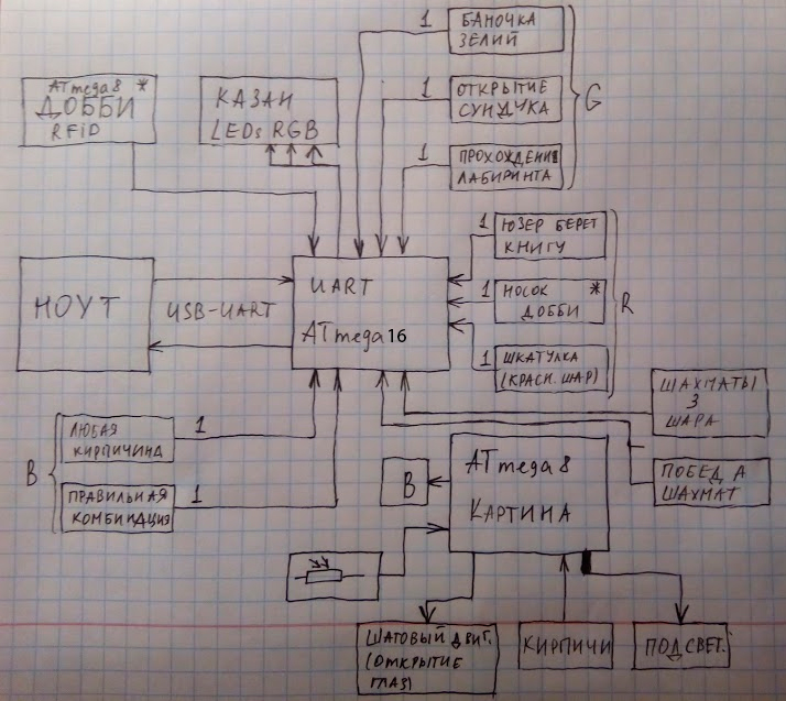
From the scheme you might think that the computer is the main one, but this is not quite so, it will take on the role of controlling and playing audio tracks, which, as you have already noticed from the previous article, we have a lot.
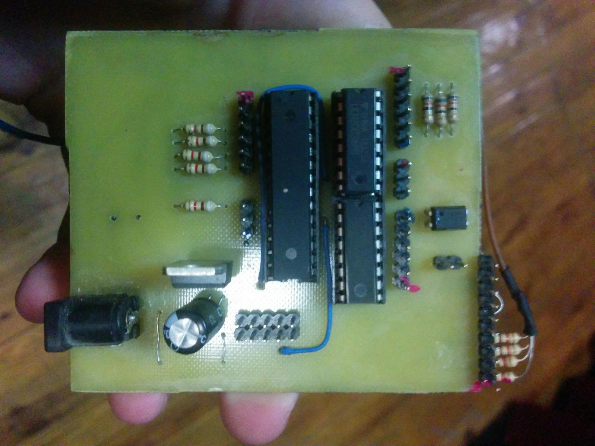
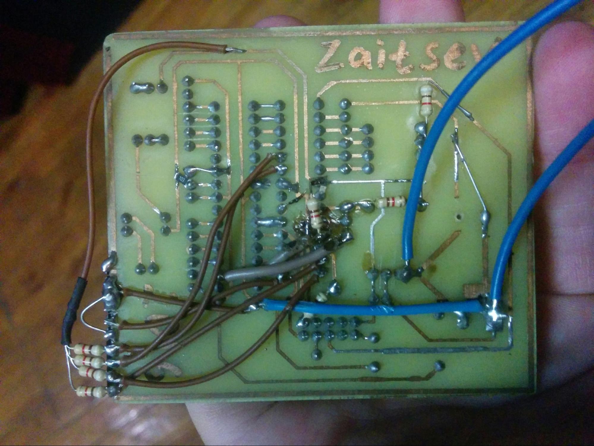
The Atmega16 microcontroller became the heart of the entire system (the only selection criterion was a sufficient amount of GPIO), which communicates with the program on a computer using the UART. All other devices are made on the Atmega8 microcontroller (great for the number of GPIO and has a reasonable price).
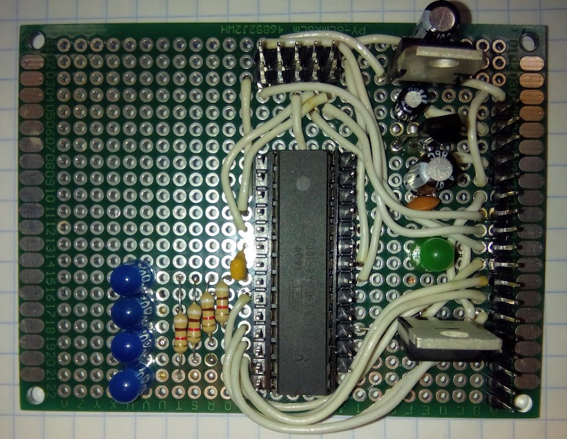
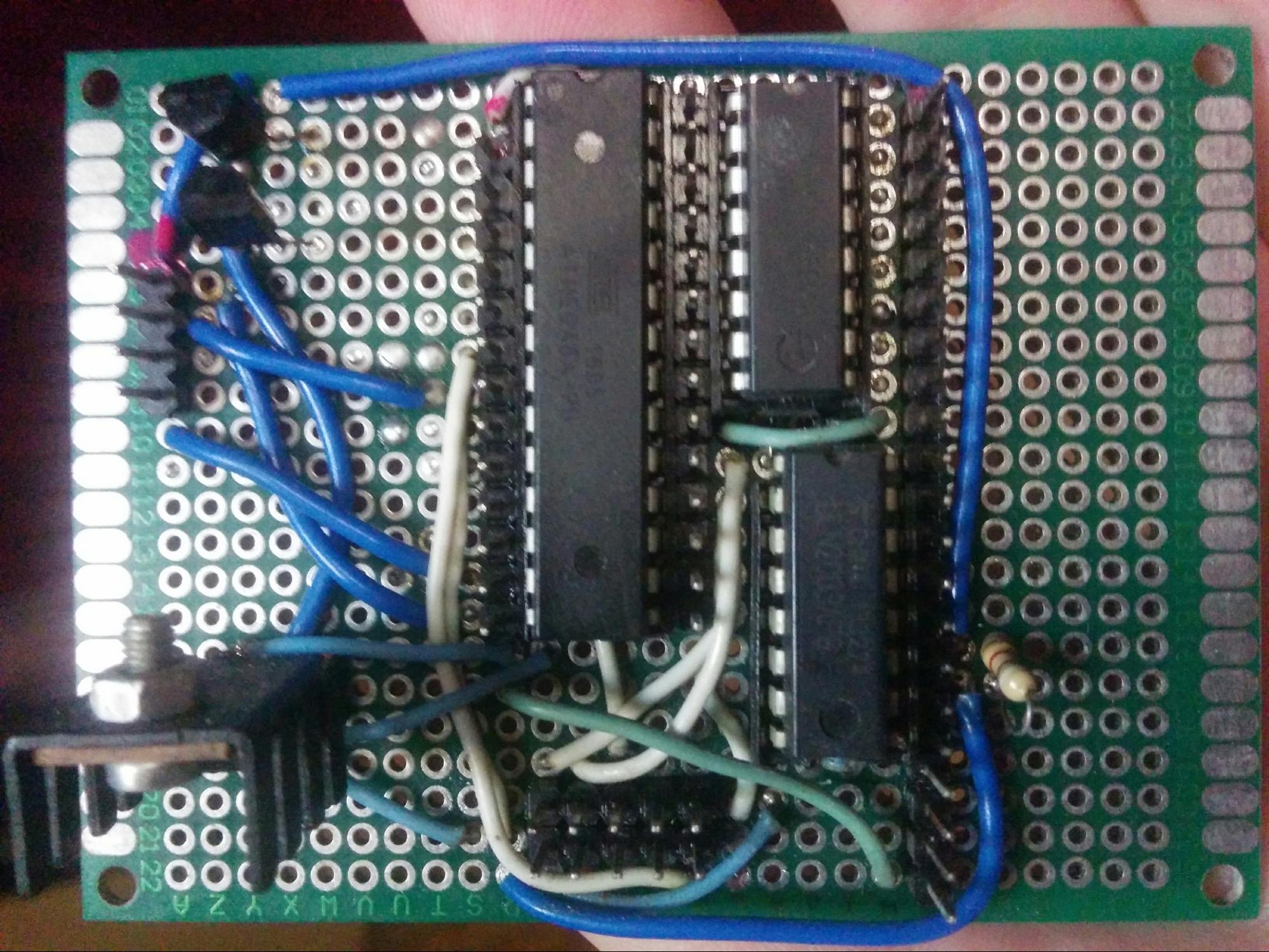
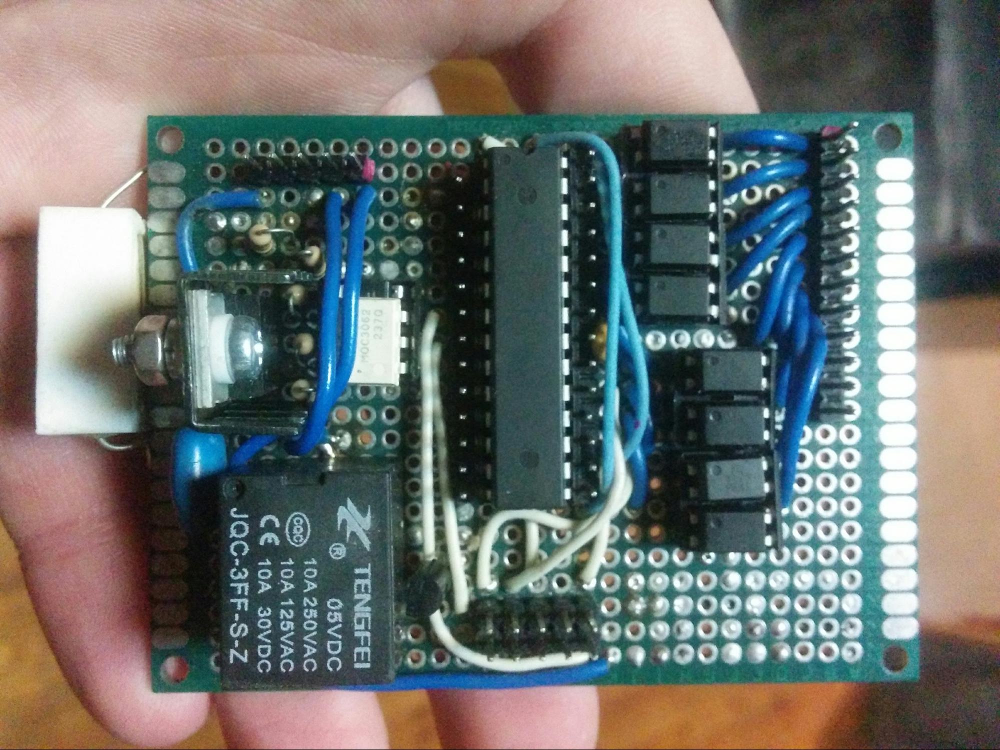
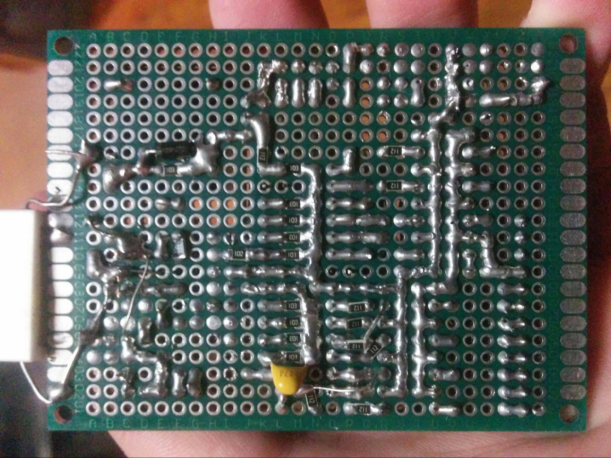
Most of the boards are soldered on the coolest two-sided layouts, respectively, all the details are in DIP packages. Part of the boards remained from the very beginning of the quest.
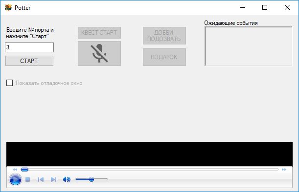
The main window of the program:
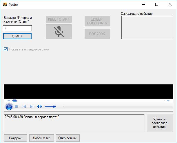
Extended window for abnormal situations:
Error window:

The main board only accepts (!) Discrete signals from other devices (through optocouplers, which can be seen in the photo), communicates with the computer, controls the LED in the bowl of memories.
The main magical weapon: wand
The magic wand is a little magic, it has a neodymium magnet embedded in the tip. He made her a kind grandfather-turner on wood for only $ 2. The main problem was to shove a magnet of maximum diameter, keeping the tip as thin as possible.

Now take a closer look at each device.
Red line
Book

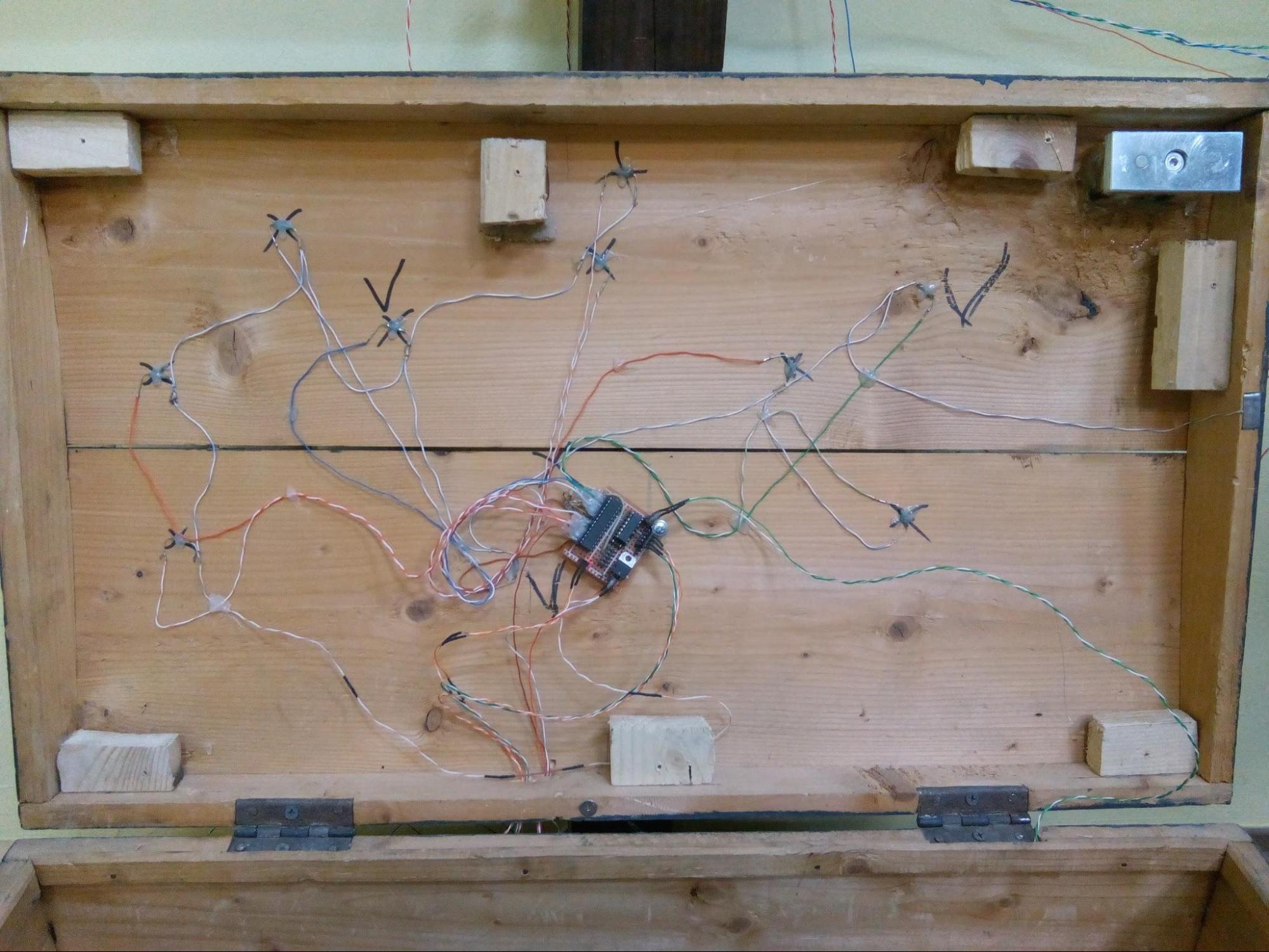
The audio event of the book is triggered by a switch that is mounted in the shelf. It is initially closed and to open it, you need to bring a wand with a magnet. The book is like a mini safe: it has batteries (Li-ion 3S), a reed switch and a transistor switch that controls the electromechanical latch (so as not to let all the current through the reed switch. At the same time, you can see a beautiful glow inside the reed switch, but it will not live long and the probability of “sticking” contacts). Everything is simple here - the wand is held up, the reed switch passes current, the transistor is open and the latch bolt is retracted. The insides of a sock safe look like this:
And the final form:
Dobby
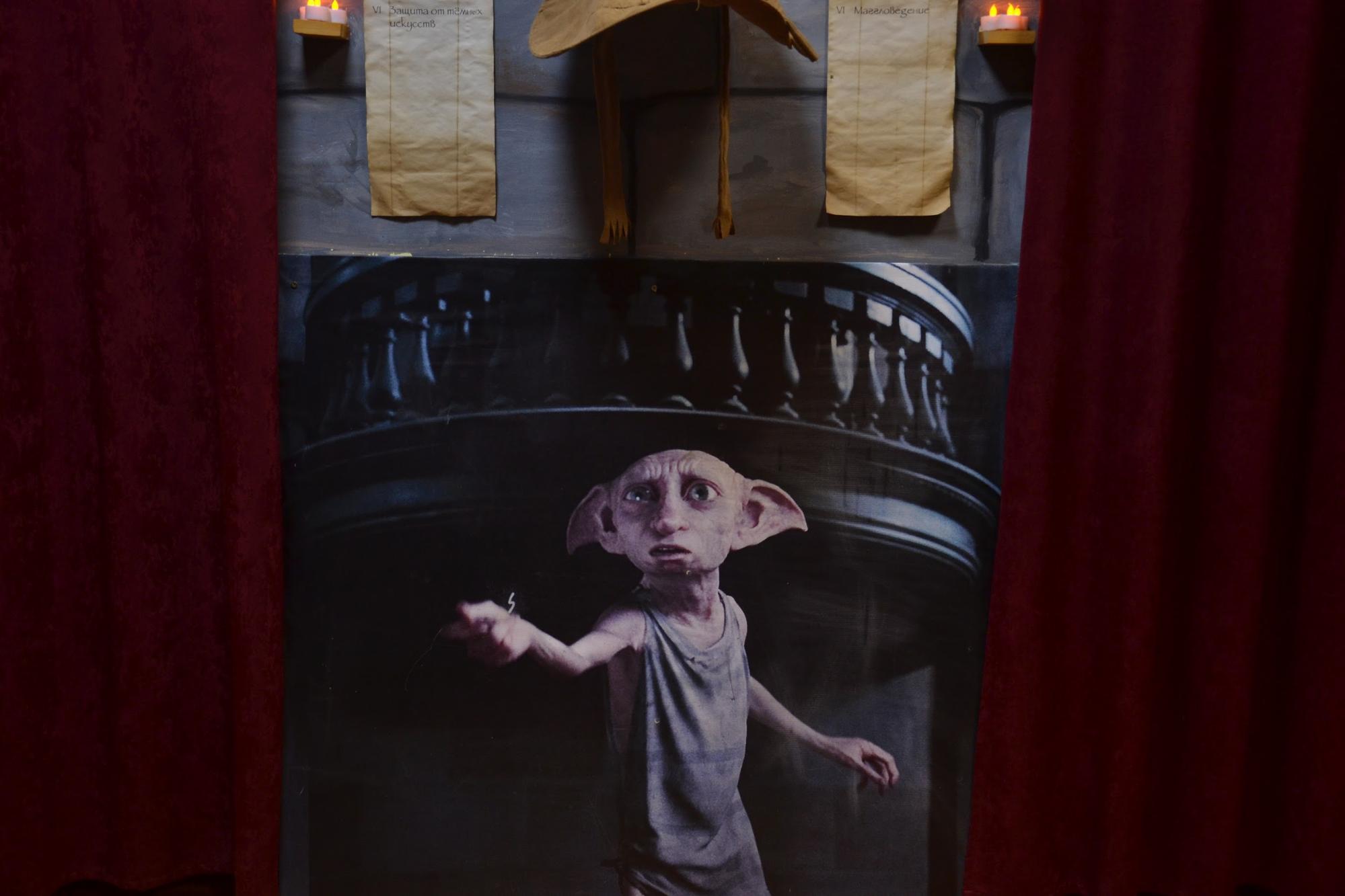
Because the task was to respond most interactively to the presentation of a sock to Dobby, the choice fell on RFID technology. To do this, I had to sew a small key chain in my sock (as from an intercom at the entrance) and put the same sign on the sock as Dobby’s on the palm of my hand. Behind the picture itself, Dobby is an RFID module.
The device is made on the Atmega8 microcontroller and the popular RC522 RFID module. After raising the sock (the triggering radius is up to 4 cm, it is just perfect), the field effect transistor opens the electromagnetic latch in the box and with the help of a spring the lid rises, the main board receives a signal and a red light illuminates in the bowl of memories.
Blue line
Fireplace
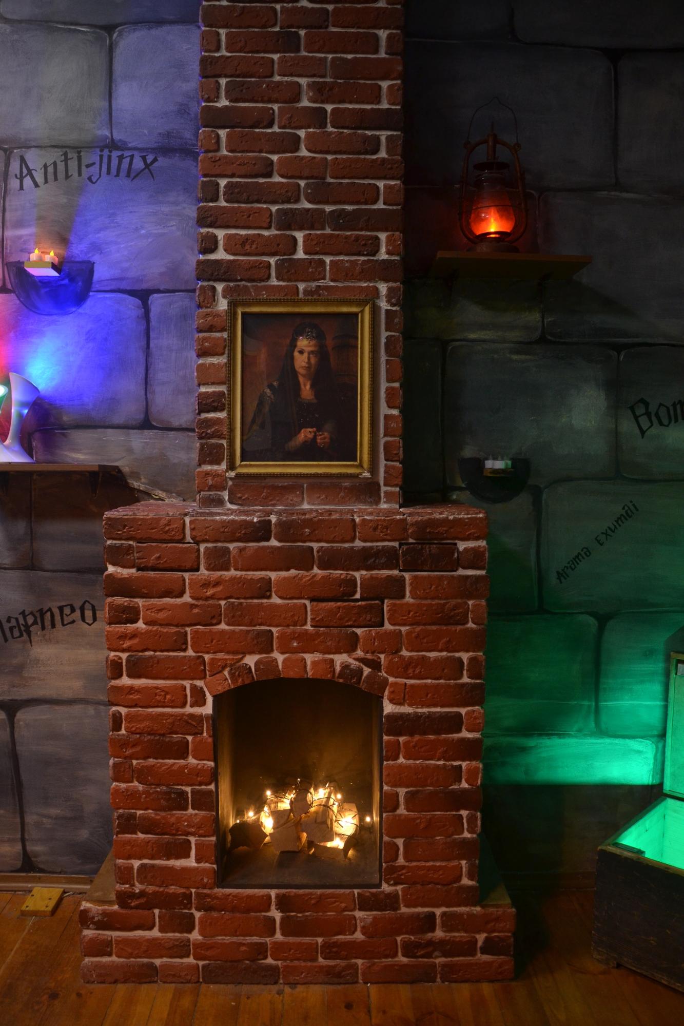
Fireplace, of course, fake. It is made of a profile and plasterboard, plastered with brick tiles.
Electronics assembled on the Atmega8. A limit switch is mounted in each brick and LED strip of blue color is connected. The bricks themselves sit on one side of the curtains, and on the other, a primitive guide with a return spring is made. When you first click on any brick, all the pushables (7 of them) are illuminated for 100ms and the picture is removed by using the stepper motor, the main card will go off, the memory will turn on and the blue light in the bowl of memories.
The stepper motor and the LED strip are controlled using the Darlington transistor assembly ULN2003 (for the curious, the theoretical part can be read here ).
Now each press on any brick inverts its state (one press - on, the next - off and so on in a circle), when you first click on any brick, the picture has an infrared sensor hidden: the IR LED shines, the radiation bounces off the approaching player and hits on the infrared transistor which using collective farm accurate resistor adjustments produce a discrete 0 or 1 output signal.
There is also a solution against parasitic illumination (especially important if users start to shine a lamp on the fireplace), another (disguised) is included in the main IR transistor circuit break, which simply turns off the microcontroller's response during illumination.
As soon as the IR sensor is triggered, the microcontroller also turns on the blinking of the desired combination, which you need to press (light) and, by the way, the pressing sequence also plays a role. Blinking the desired combination turns off all previously pressed bricks.
When the correct combination was pressed, the picture opens with a more electromechanical latch than in the caskets. For this, even had to put a rather large transformer only for this latch.
(In general, these latches are very weak, although at the peak they consume a lot of current. With their management, you need to be very careful if you give a current to it for more than 5 seconds, it can simply burn, this is how I burned one latch)


Green line
Casket
On the table there is an inconspicuous jar on the switch, if you raise it, the green light in the cauldron turns on and the box opens, in which there is a hint on the door.

(This is the same jar that is needed for Easter eggs with Dobby's jokes, which is described in the first article)
a door
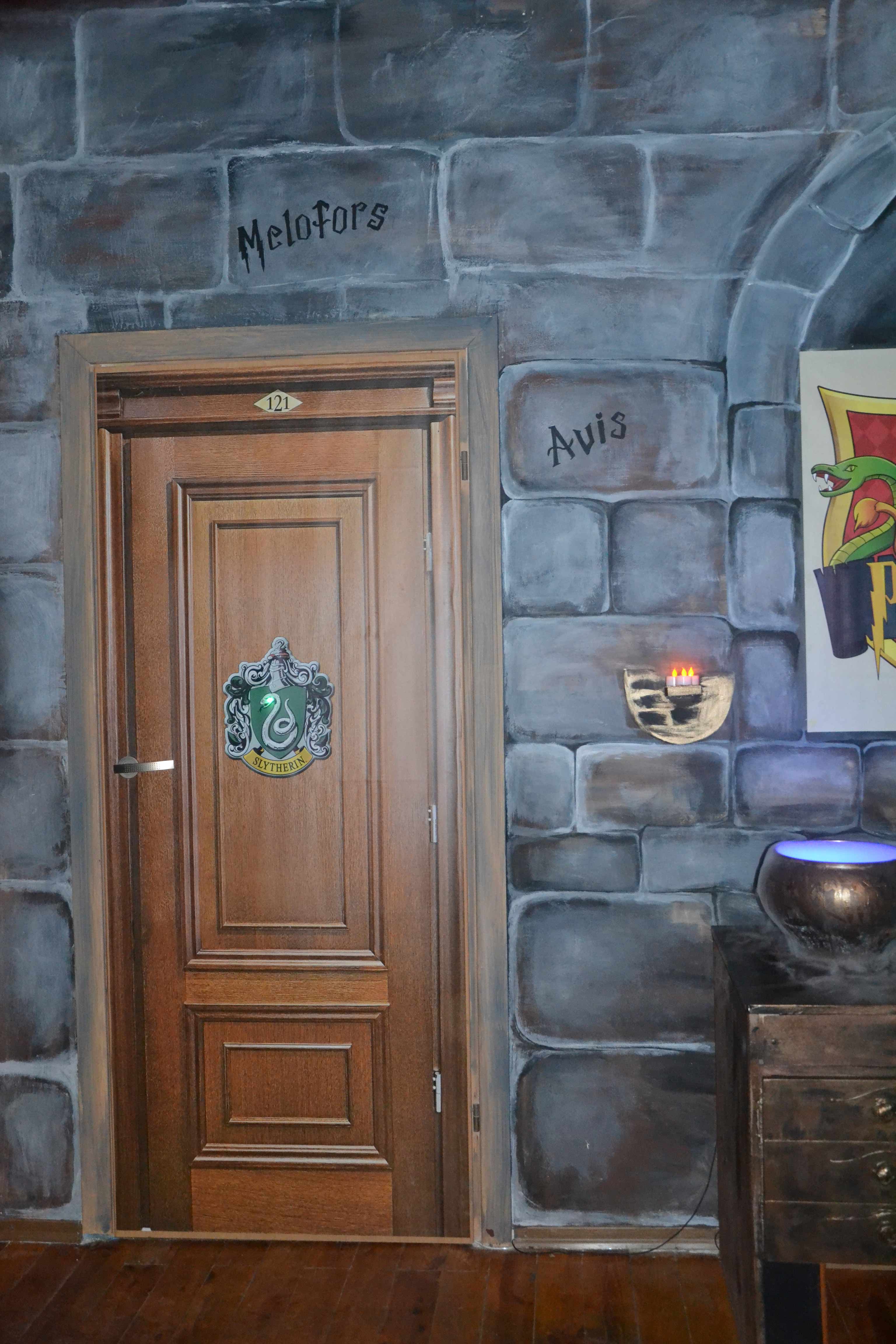
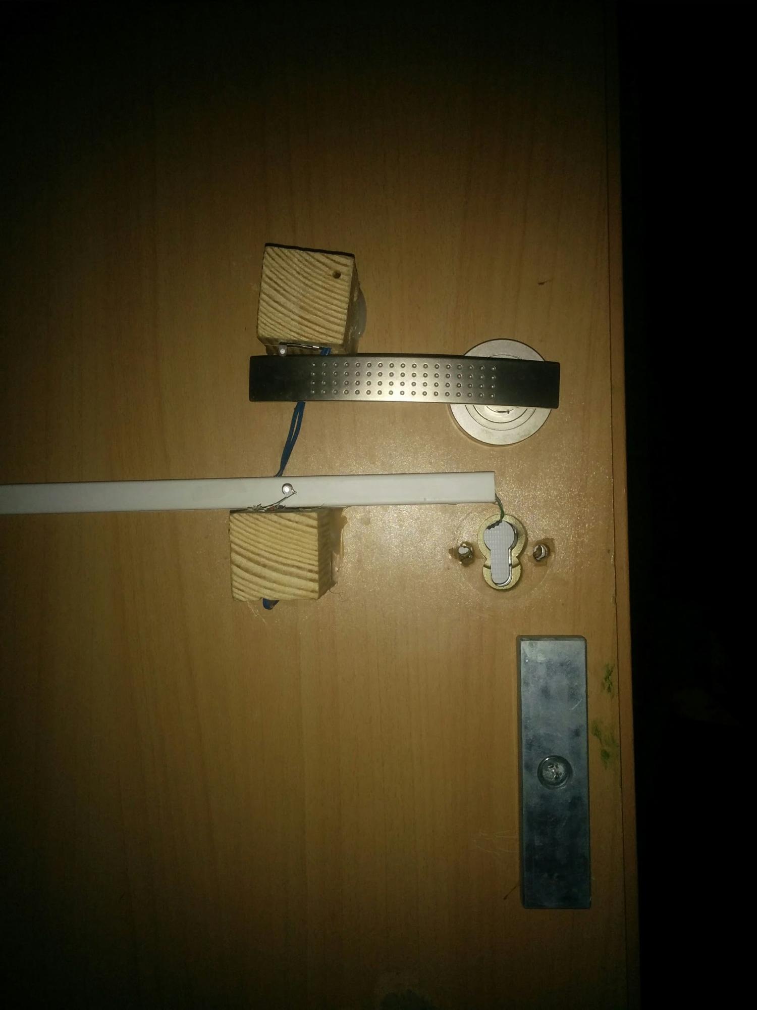
When you first press the handle down and up (for this you had to put 2 end switches on the back side of the door to respond to the full pressing of the handle), the snake on the door starts blinking.
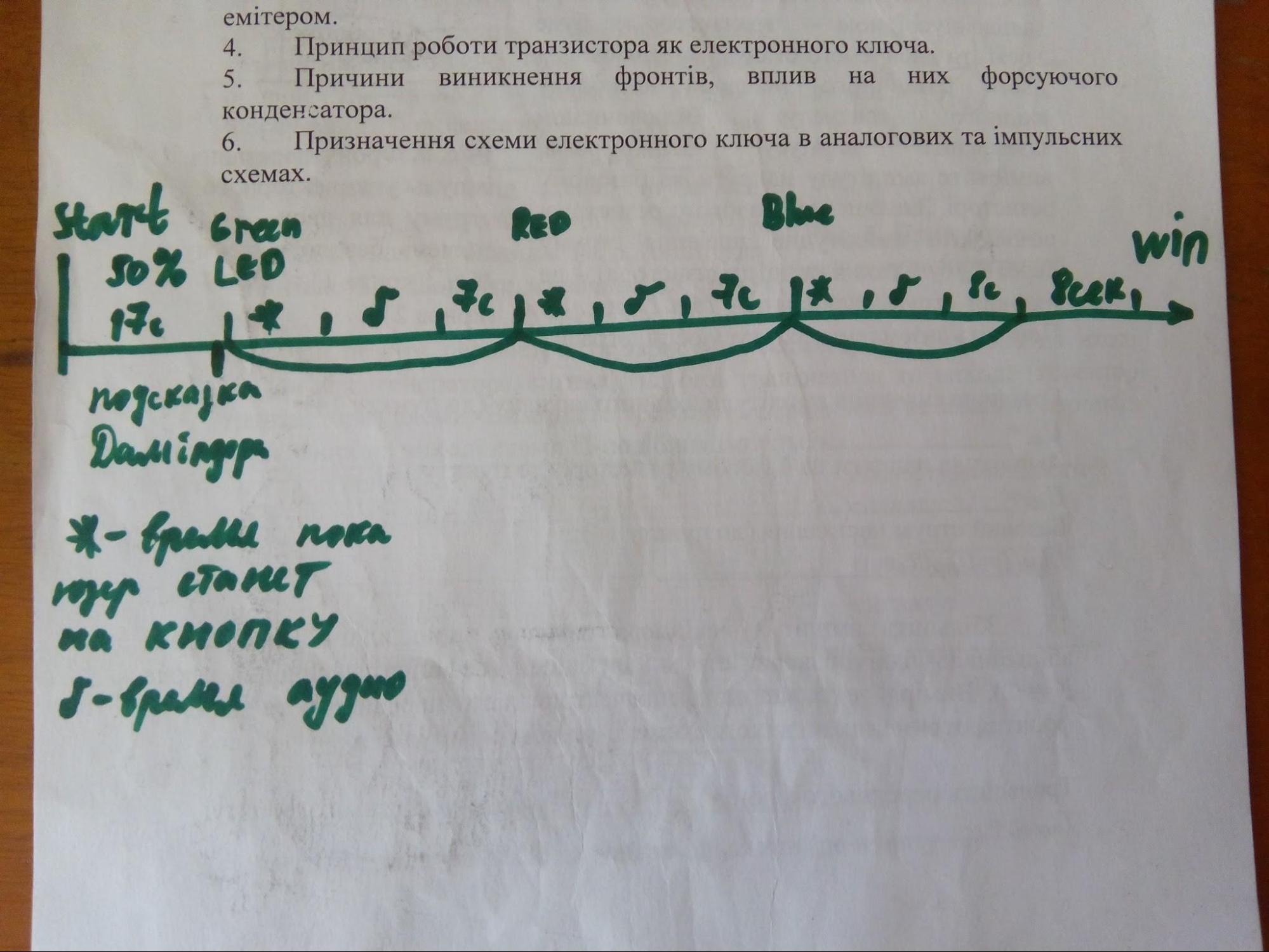
The correct algorithm for opening the door can be understood from the hint:
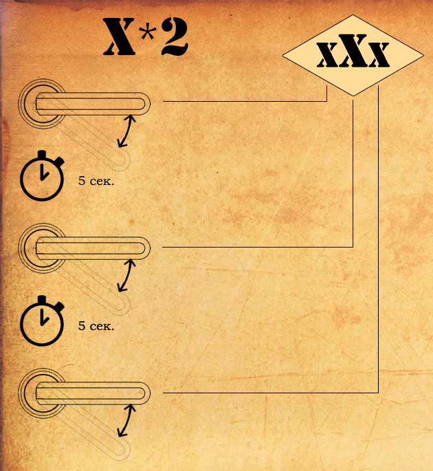
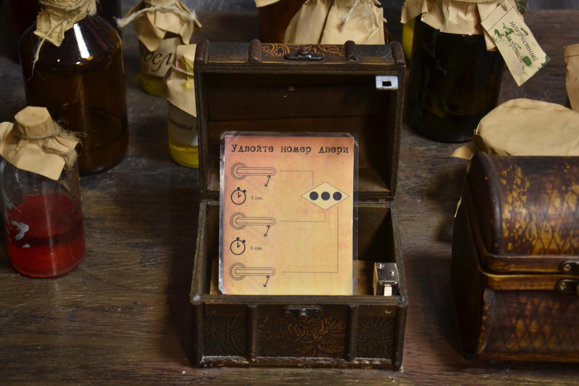
During pauses (5c), the microcontroller simply hangs in the delay, and the variable is incremented during the presses. Therefore, if you press on the handle for a long time and persistently, it will open as it is, by the way, some people opened the door in this way, not understanding how they did it. In order not to make a new board with a separate microcontroller for this simple task, several free pins were found on the maze board and everything was connected there.
Mirror Chest
10 magic symbols are applied on the lid of the chest, and the reed switches are glued from inside under them.
The user needs to bring the wand to 3 correct symbols (the sequence doesn’t play a role. The photos are ticked), however, in other drawings there are also reed switches, bringing the chopsticks to which cancels past presses, even if they were correct (so that it was impossible to open the chest all characters in a row). With the right choice of symbols, the electromagnet in the chest opens (in the chest stands the beloved Atmega8 and ULN2003). At this stage, a signal is sent to the board of the maze dial (a banal unit from a pin of one MK to a pin of the other through a transistor switch) and in the maze twirls begin to rotate.
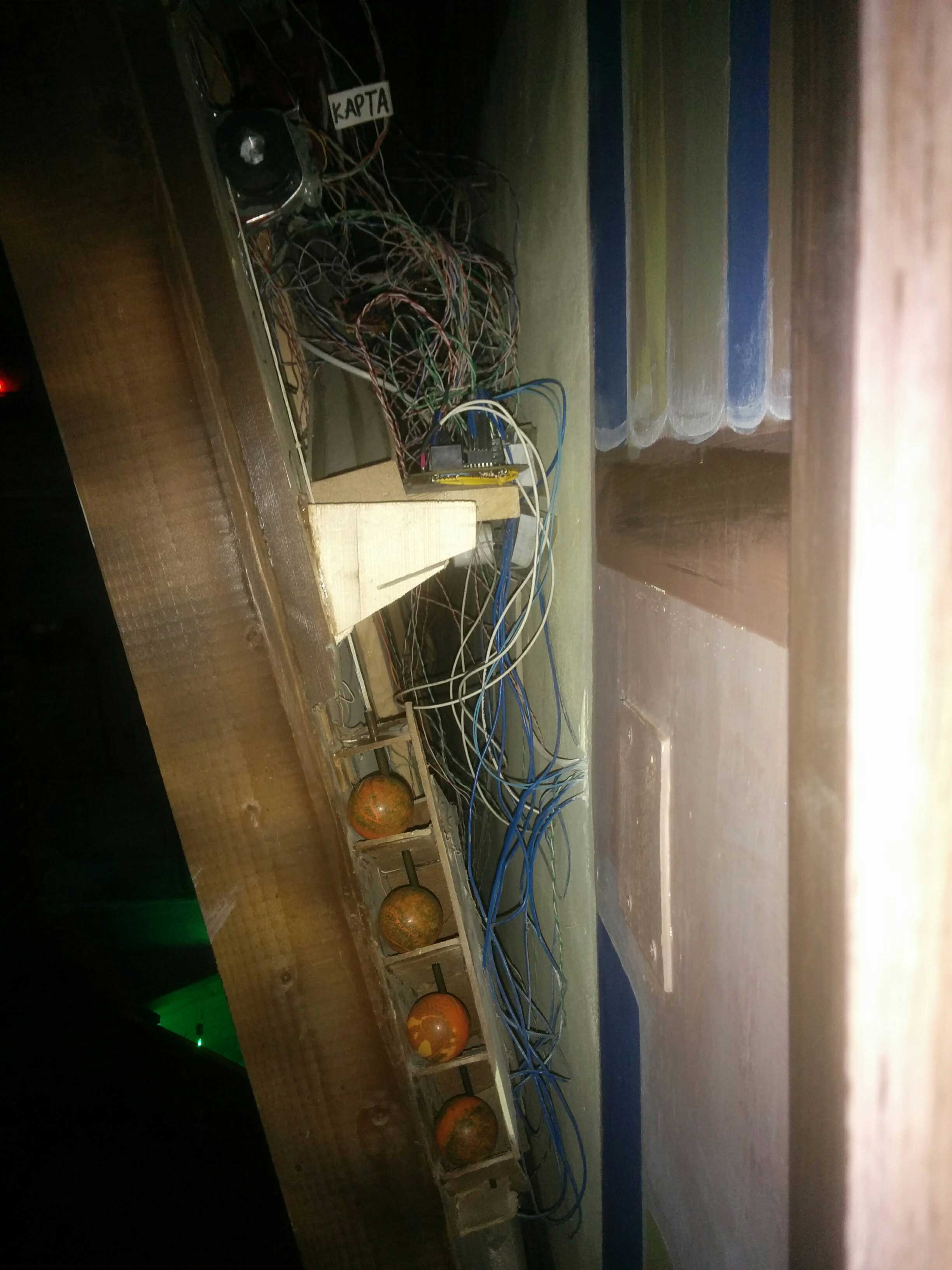
Labyrinth
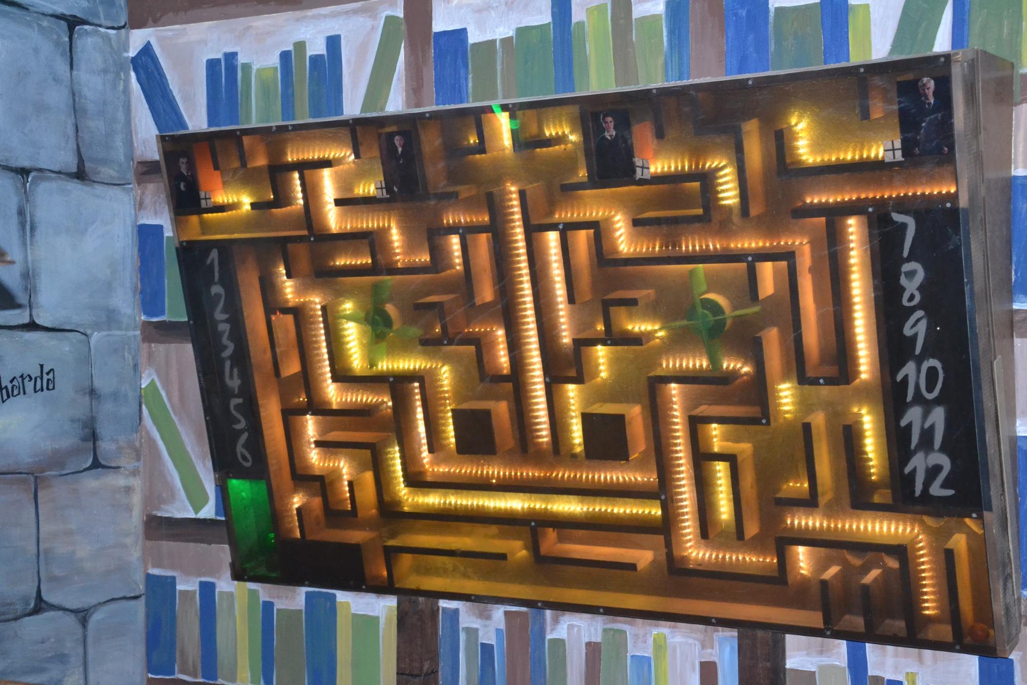
This enormous design, we sooooo underestimated. She took a lot of time and effort to create, but the result was that. The work of a “big black object on the wall” required a lot of GPIO (everything was done in the most primitive way - no multiplexers / demultiplexers, only hardcore!), So I had to split the device into functional nodes - the dial and the labyrinth itself. Each node is made on the same Atmega8.

In the labyrinth principle, everything is simple (although then it seemed not quite easy :)). A lot of problems brought the ball at the end of its path. Randomized interferences constantly interfered with the operation of the optocouplers.
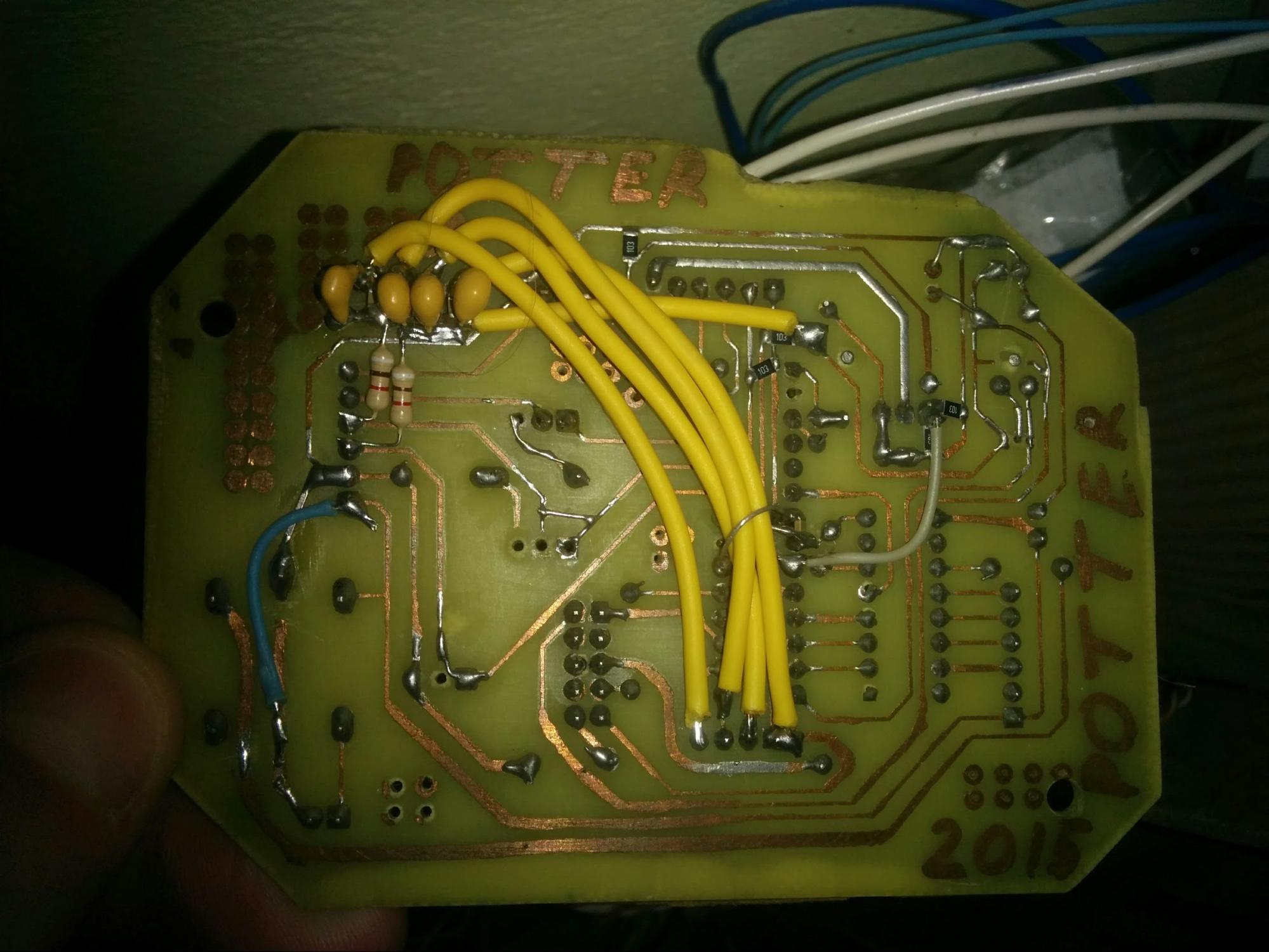
It was these yellow capacitors that helped solve the problem of the random operation of optocouplers.
At the end of the maze opens access to the green sphere. The system of providing access to it is made on the lock of the car door. (In terms of price / power, he is a monster!).
Initially it was not planned to issue 1 ball for the game, but I had to make adjustments at the final stage, since in the balls of the magnets, they can “stick together” and separate them very problematically, so in order to eliminate this probability in the game, it was decided to issue the balls in turns. Submission is carried out using a stepper motor and an improvised damper from the old spinning.
Unification of forces
Chess
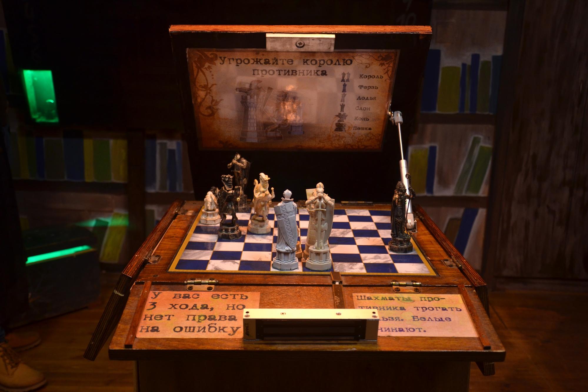
After much deliberation, the task with a single algorithm was thought out (under certain conditions, which are negotiated to the players). It remained to be small - to implement a system of chess movement and reaction to the actions of the players :)


The mechanism is made of studs and nuts M8, Chinese bearings and wood. A magnet is mounted in each figure with the help of which the mechanism moves them. The coupling of the motor with the pin is made from the component part of the glue gun, which we had consumables, due to the wildly increased consumption of silicone glue.
Who knows, the figures we took from the Harry Potter chess set, they still make different sounds, glow, etc. I could not leave these features just like that, moved these handkerchiefs under the board and it turned out that when they walk a horse, he laughs, and in the end you can hear the sound of a fallen king.
After the victory in chess, the cabinet door opens (opens quickly with the help of a gas furniture guide).
Before turning to the most interesting, I want to tell you about a cauldron (a cup of memories) and an intercom for the administrator to communicate with visitors during the game.
Chalice of memories
Let's start with the fact that this ten-liter aluminum cauldron was found in the garage in the grandfather, as an attribute of Soviet cuisine :) The idea to make a cup of memories from which to blow smoke (and in fact steam) hung in thoughts for a long time, but we reached the correct implementation a little bit later.
Ultrasonic humidifiers in the amount of 6 (!!!) pcs and with a total power of about 100 W became a fog former!

Alas, the photo has not been preserved, but the device is very simple, made according to the scheme:
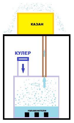
The dimensions were made so as to ideally place this system on the table (place for the boxes).
Intercom
My poor knowledge of analog circuitry did not allow me to solve this problem with a hitch. After long and unsuccessful attempts (but as it turned out later, the decision was quite close!) I asked my friend from Kherson to make me such a device.
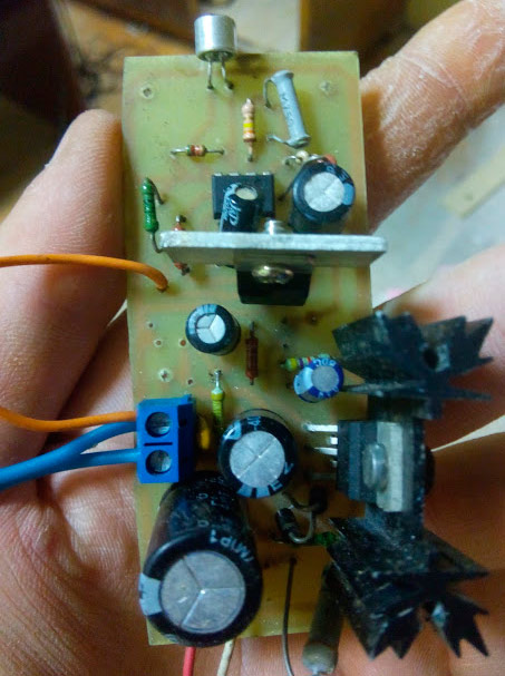
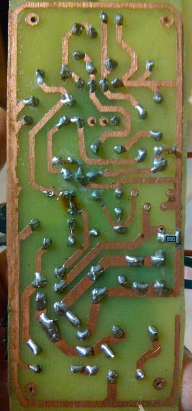
The preamplifier is made on the NE5532 low-noise operational amplifier, followed by the TDA2006.

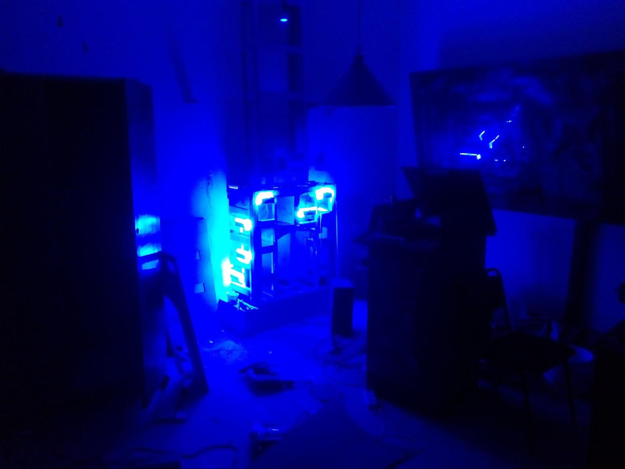
Finally, we move on to one of the most difficult systems in the room — the final battle with the Dark Lord!
The battle
The idea was to realize at least something like the “battle” of the player (Harry Potter) with Volan de Mort. For greater effect, wind was added (2 fans). We thought through many options, and then a friend suggested to me about the WS2812 addressable LEDs. It is now even the most lazy arduinschiki talk about what cool things they did, but then the WS2812 were less well known, but they became our salvation! Without them, to realize our idea was simply unreal!
5m of the LED strip were folded in half, and inside was stretched wire for the reed switch. The first 5m tapes were safely burned in an attempt to save on the power supply for the same tape :)
We started the development with setting timings:
Some troubles added the inclusion of fans. If you bring / remove the wand frequently, then the relay (initially tried to turn on the fans through the relay), the microcontroller simply demolished the tower. As a result, I learned about the ability to control the load 220V through optosimmistor. After that I do not use the relay :)
It is also worth mentioning that serious computing power (on the scale of Atmega8) was required to be given to the management of address LED strip. At first, the work of the tape was very hanging, we were tormented for a long time, we could not understand why. As a result, I had to find on the Internet a person who wrote the library for this tape and ask for help from him. The reason was simple: MK did not have time to execute the code in the interrupt handler, and as soon as we fixed it, everything worked fine!
→ Programs for microcontrollers
→ Programs for computers
According to our idea, this should be the last article, but we still want to tell you a lot of interesting things, so I want to announce the release of two more articles on how to make a real Hogwarts (1) and thrash out of the office (2) along with unrealized ideas.
It will be interesting!