Arrow LED-watch for teaching soldering SMD components
The last year in our hackspace, several projects are being developed in parallel, which from time to time give birth to this world of new glands, primarily educational ones.
In this article I will talk about one such interesting thing that we did some time ago. This is a SMD soldering training kit - LED watch. Under the cut a detailed description of the set, the reasons for the appearance, and video tutorial on SMD soldering!
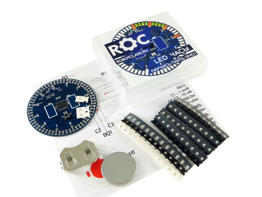
In general, we take ideas for our glands from the educational process, which constantly rages around us. This may be Wishlist our friendly teachers of circles, or the students themselves, their parents. Among the wishes, most occupy different sensors, power modules, controllers. Another part is training stands for sharpening skills of circuit assembly, soldering, and programming.
Teaching schoolchildren, students, and their mentors to surface mount is one of those universal wishes. And to realize it does not require a lot of imagination. The development of any skill is to repeat the same action. Until the hand starts to poke the soldering iron at exactly the right place at the right angle and with the right force. Until you start to see beauty at each point of your soldering.
For training skills need a suitable stand. You can buy from the Chinese board with a bunch of seats for SMD components, without any function. You can find more interesting sets, but sometimes too complicated for the first battle (the same POV globe).
We decided to make such a stand in the form of an analog watch with a bunch of SMD components, record a video tutorial for all of this, and teach our children at least technology of the past.
Translated from English, SMD is a surface mounted device, i.e. “surface mounted device”. Unlike the technologies that precede the next stage of miniaturization, SMD elements take up much less space. SMD allows you to make the device very compact. Just look at the motherboard of any smartphone to understand what is at stake.
SMD come in different sizes. Rectangular-shaped elements such as LEDs or resistors are measured by side lengths. For example, on Arduino, LEDs 0805 are installed. Translated from the inch to metric system, this corresponds to a size of 2 x 1.25 mm. And most ceramic capacitors on the same board have a size of 0603 = 1.6 x 0.8 mm.
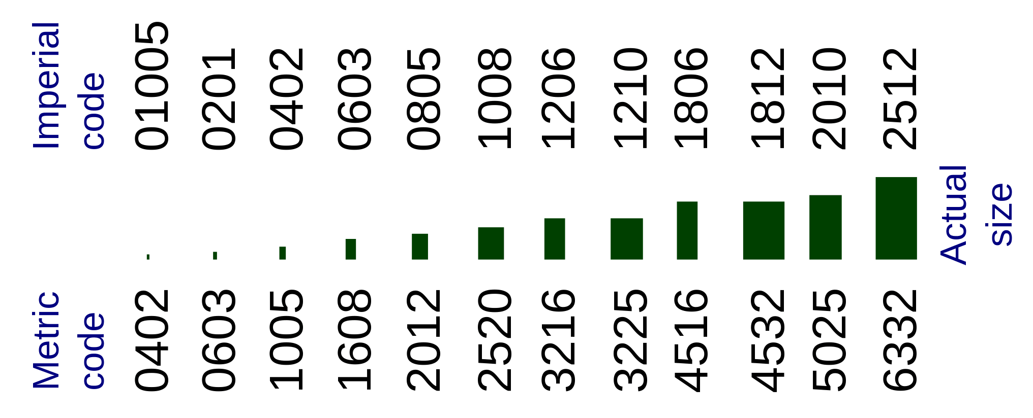
In conventional diodes, the dimensions are different. For example, the size of the SOD-123 diode corresponds to 3.68 x 1.17 x 1.60 mm. And here is an example of a three-legged transistor: SOT-323 = 2 x 1.25 x 0.95 mm. In general, there is a wide variety of types and sizes of SMD enclosures.
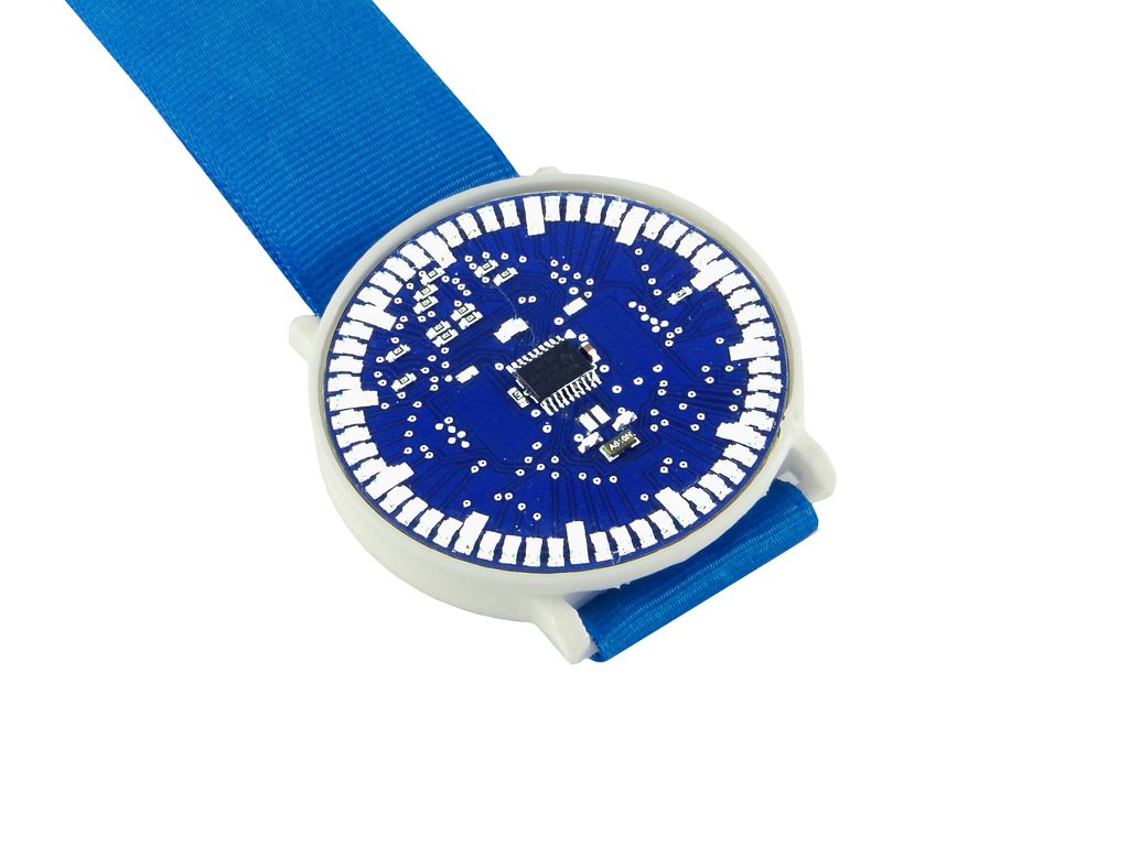
As it became clear, the kit contains SMD of different sizes and a printed circuit board, on which all this needs to be soldered. The board already has a microcontroller and a quartz resonator, which we did not venture to give separately (at least in this version).
The bottom side of the board is very similar to the positron brain:
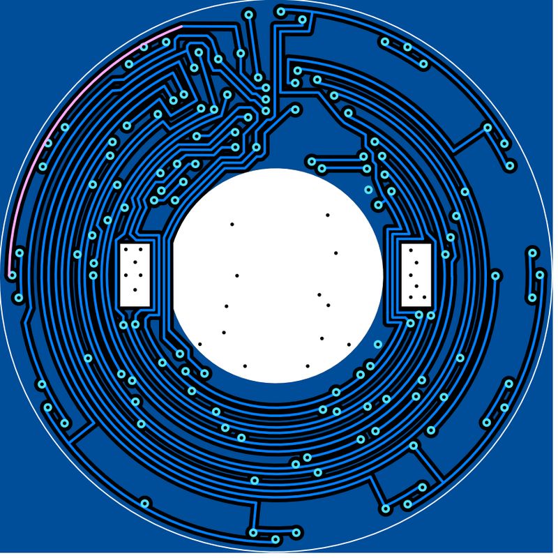
Top: The

heart of the clock is the MSP430G2553 microcontroller. The selection may seem exotic. However, the clock is not positioned as a stand for learning programming. We applied what was optimal in the circumstances.
To make the clock work, you need to mount 61 LEDs, some resistors and ceramic capacitors on the board. Training goes step by step, with gradual complication. First, you need to solder 12 of the largest LEDs 1206, then another 49, but already smaller - 0805. In the end, you will need to solder just a bit of the smallest resistors and capacitors 0603.
By putting everything together, you will get a working wrist LED clock with a virtual arrow!
The kit includes:
Now for the tool. In general, most schoolchildren are forced to solder Daddy's or, most likely, already 60-80 W grandfathers soldering irons with a thick sting. Skillfully, it is possible to solder SMD with such an apparatus, but this is a form of violence.
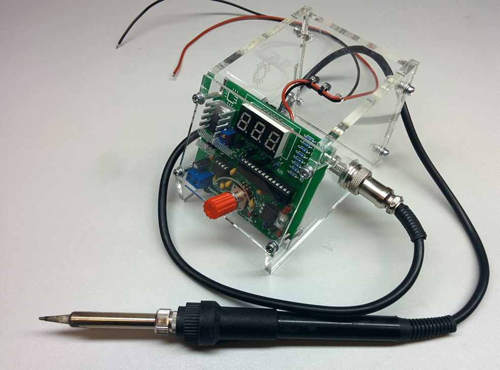
To switch from SMD installation, it is recommended to get a soldering station with a thin tip. It is possible the simplest Chinese, or here is such a DIY sample (of our good colleague): You will also need tweezers with thin and even lips. Tweezers generally deserve a separate post. Some careless people constantly strive to pick something up with sharp tweezers, from which his lips will bend and dull. I strongly recommend holding tweezers for SMD in a well-protected place!
The next need is solder and flux. Formally, you can use solder with flux and do not use anything more. But in practice, especially for a beginner, it is better to use a good liquid or gel flux. AmTech is perfect, but LTI-120 with a brush will do. Solder can be the most common, but thin: 0.5 - 0.8 mm with flux.
Instead of a pile of text, our best of the best in the manipulation of micro-objects ( Stepan Glushkov ) made a video tutorial on the basics of SMD soldering using the example of these LED hours.
Finally, that's what happens if you have enough patience.
Source codes of the program and Geber-files of the board can be downloaded on the RobotClass site .
In our unclassified laboratory RobotClass, other interesting kits are being prepared, including on soldering skills training. We will be happy to hear criticism!
In this article I will talk about one such interesting thing that we did some time ago. This is a SMD soldering training kit - LED watch. Under the cut a detailed description of the set, the reasons for the appearance, and video tutorial on SMD soldering!

In general, we take ideas for our glands from the educational process, which constantly rages around us. This may be Wishlist our friendly teachers of circles, or the students themselves, their parents. Among the wishes, most occupy different sensors, power modules, controllers. Another part is training stands for sharpening skills of circuit assembly, soldering, and programming.
Teaching schoolchildren, students, and their mentors to surface mount is one of those universal wishes. And to realize it does not require a lot of imagination. The development of any skill is to repeat the same action. Until the hand starts to poke the soldering iron at exactly the right place at the right angle and with the right force. Until you start to see beauty at each point of your soldering.
For training skills need a suitable stand. You can buy from the Chinese board with a bunch of seats for SMD components, without any function. You can find more interesting sets, but sometimes too complicated for the first battle (the same POV globe).
We decided to make such a stand in the form of an analog watch with a bunch of SMD components, record a video tutorial for all of this, and teach our children at least technology of the past.
For those who are not with us: what is SMD?
Translated from English, SMD is a surface mounted device, i.e. “surface mounted device”. Unlike the technologies that precede the next stage of miniaturization, SMD elements take up much less space. SMD allows you to make the device very compact. Just look at the motherboard of any smartphone to understand what is at stake.
SMD come in different sizes. Rectangular-shaped elements such as LEDs or resistors are measured by side lengths. For example, on Arduino, LEDs 0805 are installed. Translated from the inch to metric system, this corresponds to a size of 2 x 1.25 mm. And most ceramic capacitors on the same board have a size of 0603 = 1.6 x 0.8 mm.

In conventional diodes, the dimensions are different. For example, the size of the SOD-123 diode corresponds to 3.68 x 1.17 x 1.60 mm. And here is an example of a three-legged transistor: SOT-323 = 2 x 1.25 x 0.95 mm. In general, there is a wide variety of types and sizes of SMD enclosures.
LED Watch Set
As it became clear, the kit contains SMD of different sizes and a printed circuit board, on which all this needs to be soldered. The board already has a microcontroller and a quartz resonator, which we did not venture to give separately (at least in this version).
The bottom side of the board is very similar to the positron brain:

Top: The

heart of the clock is the MSP430G2553 microcontroller. The selection may seem exotic. However, the clock is not positioned as a stand for learning programming. We applied what was optimal in the circumstances.
To make the clock work, you need to mount 61 LEDs, some resistors and ceramic capacitors on the board. Training goes step by step, with gradual complication. First, you need to solder 12 of the largest LEDs 1206, then another 49, but already smaller - 0805. In the end, you will need to solder just a bit of the smallest resistors and capacitors 0603.
By putting everything together, you will get a working wrist LED clock with a virtual arrow!
The kit includes:
- printed circuit board with a pre-installed and already programmed microcontroller;
- LEDs size 1206 and 0805;
- size 0603 resistors;
- capacitors size 0603;
- fastening of the battery;
- CR2032 battery.
Now for the tool. In general, most schoolchildren are forced to solder Daddy's or, most likely, already 60-80 W grandfathers soldering irons with a thick sting. Skillfully, it is possible to solder SMD with such an apparatus, but this is a form of violence.
To switch from SMD installation, it is recommended to get a soldering station with a thin tip. It is possible the simplest Chinese, or here is such a DIY sample (of our good colleague): You will also need tweezers with thin and even lips. Tweezers generally deserve a separate post. Some careless people constantly strive to pick something up with sharp tweezers, from which his lips will bend and dull. I strongly recommend holding tweezers for SMD in a well-protected place!

The next need is solder and flux. Formally, you can use solder with flux and do not use anything more. But in practice, especially for a beginner, it is better to use a good liquid or gel flux. AmTech is perfect, but LTI-120 with a brush will do. Solder can be the most common, but thin: 0.5 - 0.8 mm with flux.
SMD video tutorial
Instead of a pile of text, our best of the best in the manipulation of micro-objects ( Stepan Glushkov ) made a video tutorial on the basics of SMD soldering using the example of these LED hours.
Demonstration of work
Finally, that's what happens if you have enough patience.

Source codes of the program and Geber-files of the board can be downloaded on the RobotClass site .
In our unclassified laboratory RobotClass, other interesting kits are being prepared, including on soldering skills training. We will be happy to hear criticism!
