Ethernet lamp for Continuous Integration and more
 Hello to all users! Not so long ago, the Amperka project was launched . Interest was noticeable, so we continue to develop. And this is our first corporate blog post.
 Today I want to share the experience of creating a gadget based on Arduino, which may be useful for you. And if it doesn’t turn out to be useful, I hope some aspects of working on the device will be interesting.
This gadget is a lamp that glows in different colors depending on the messages going to it on the local network. Why is this needed? Personally, as a member of a team of four programmers, I need this thing to indicate the operation of Continuous Integrationserver. The server, of course, is able to send notifications to e-mail and jabber when the assembly fails, but it is boring and not convenient: there is no way to look somewhere and instantly understand what is happening with the project: everything is in order, everything is bad, or right now it’s going assembly.
The problem is not new. I read several times how the people went hungry by screwing a traffic light, lava lamp and usb flasher to the computer. I wanted to do something simple that I could bring to the office, stick it in the hub and that’s it! And so that it works without a tambourine. Well, let's try! We need Arduino, an Ethernet Shield for it, a defective lamp from Leroy-Merlin, three LED strips of different colors, a handful of small things and a reserve of patience.
The device should work without settings, immediately, scooping up information from an ethernet hub. Thinking about how best to do this, I decided: let the lamp just get its IP through DHCP, and then listen to a specific port and catch UDP packets that tell it the color that needs to be lit. As they said last, so shine. And whoever will send them there, the lamp does not concern. If you do so, then the gadget can be used for anything, not only for the CI server.
Prototype
Let the device listen on port 7190 and catch packets of the form: “4 bytes header, 1 byte - any for future needs, 3 bytes RGB color”. And if there is no signal for 30 seconds, let it glow white: it will be possible to understand that something is wrong.
We sit down to write the firmware. And here is the first disappointment: the standard library for Arduino does not provide either DHCP or UDP. But Arduino would not be them, if not for the community. The necessary developments from enthusiasts were found quite quickly ( DHCP , UDP ). I will not clutter up this post with code. The entire source code for the wonder lamp firmware is open on Bitbucket . Here, the firmware itself and related utilities, which will be described later. If you're just wondering what the code looks like, start digging from the main app.cpp file. With a basic knowledge of C ++, the code should be clear.
To quickly test whether the lamp understands network packets, we will make a small script that accepts a color from the command line that needs to be broadcast and broadcast it, say, every second. Mmmm ... but what IP will the lamp be given? You can, of course, get confused and implement some kind of discovery-service to search for ethernet-lamps in the network, but it seems to me - this is too much. Then I remembered that there is a wonderful
thing IP-broadcast . The bottom line is: if you send a packet to IP 192.168.1. 255 , then all devices with an IP of the form 192.168.1.xxx will hear it.
The result is such a script .
With software sorted out, take on hardware. In the firmware, outputs 7, 8, 9 are used to control colors and it is assumed that red, green and white colors will be used. We
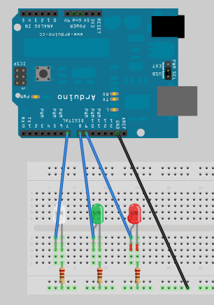
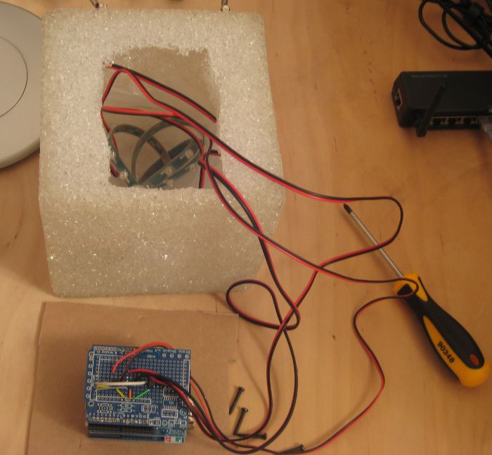
put together such a scheme: We flash Arduino. Nothing works! We fix, flash, try. We fix, flash, try. And so many times until the firmware code becomes debugged and does what is required of it. Success!
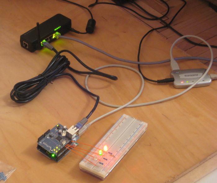
The photo shows a situation where packets are sent over the network with a request to glow in red and green.
More light
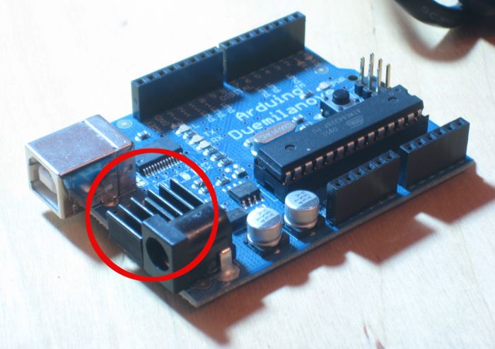
For the prototype, low-power 5mm LEDs were used. Weak for a geek lamp. But the LED strip for outdoor advertising is the thing that you need. But there is a small problem. It is assumed that 12 V will be supplied to the tape, and Arduno can only issue 5 on its paws.
They will not be enough even to somehow light the tape. If Arduino is powered by a separate power supply unit, not USB, it can be fed from 7.5 to 12 V. This voltage then passes through the voltage regulator on the Arduino itself to turn into native 5 V, but before that, the voltage can be taken from the Vin contact.
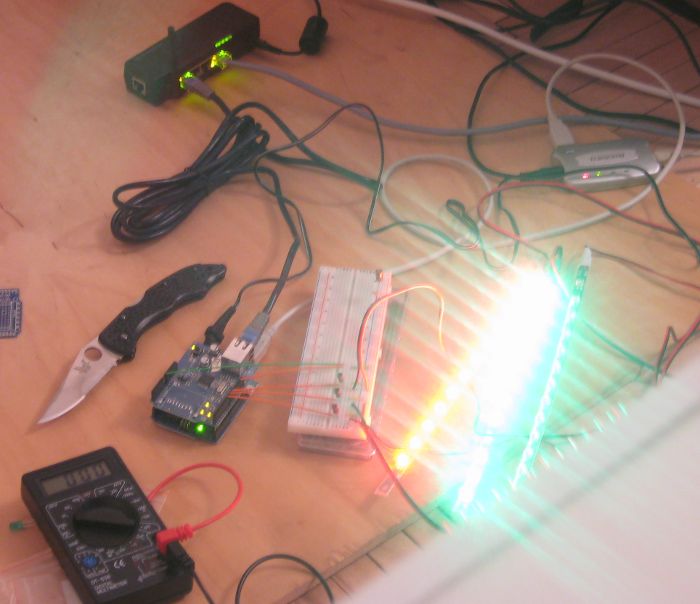
It is resolved. Vin will be fed to the tapes, and we will block / enable the flow of current using transistors:

Turn on! Drum roll ... Barbell! Does not shine! Ethernet shield, Arduino blinks with its bulbs, and the tapes are silent. I rang the whole scheme: everything seems to work. But no. I danced around for a long time, but without result. Leaving the whole structure connected, he left to make tea. And what was my surprise when I returned, I saw that the white ribbon is glowing. Thus, the device reported that the IP address was received, there is a connection, there were simply no UDP commands yet. Excellent! We send a command to turn on red. Drum roll ... Again the bar! As it was white, it remained.
After repeating the experiment a couple of times, I suspected that the Ethernet Shield lacked power. Yes, that is right. If, in addition to the external 12V power, connect USB, then everything works.
A couple of hours trying to understand why I stepped back and decided to continue: well, let USB be turned on. The gadget is stationary, "for yourself", and besides, there remains a loophole through which you can access the microcontroller without disassembling the lamp.
Leaving the device to work for a long time, I noticed that the voltage regulator on Arduino decently warmed up. You can’t hold a finger for a long time. Since I want the lamp to work around the clock, for every fireman, with the help of hot glue, I attached a small radiator to it
Packaging
All this construction now needs to be placed in the case. To do this, I bought a regular lamp made of incomprehensible soft material, similar to pieces of thick polyethylene glued together. So, we gutted the lamp: we take out all the native stuffing and send it to the bin

Together with the breadboard, putting this whole thing inside the lamp was problematic. This is not reliable. Therefore, from the breadboard we transfer the entire circuit to the circuit board. The quality of the board is quite suitable for Proto Shield. Solder the legs, install transistors, solder the wires. We call the payment received to make sure that where there is contact, there is, and where it is not needed, no. Everything seems to be fine. Putting the design together. It turns out here is such a sandwich:

Cross fingers, turn on. Works!
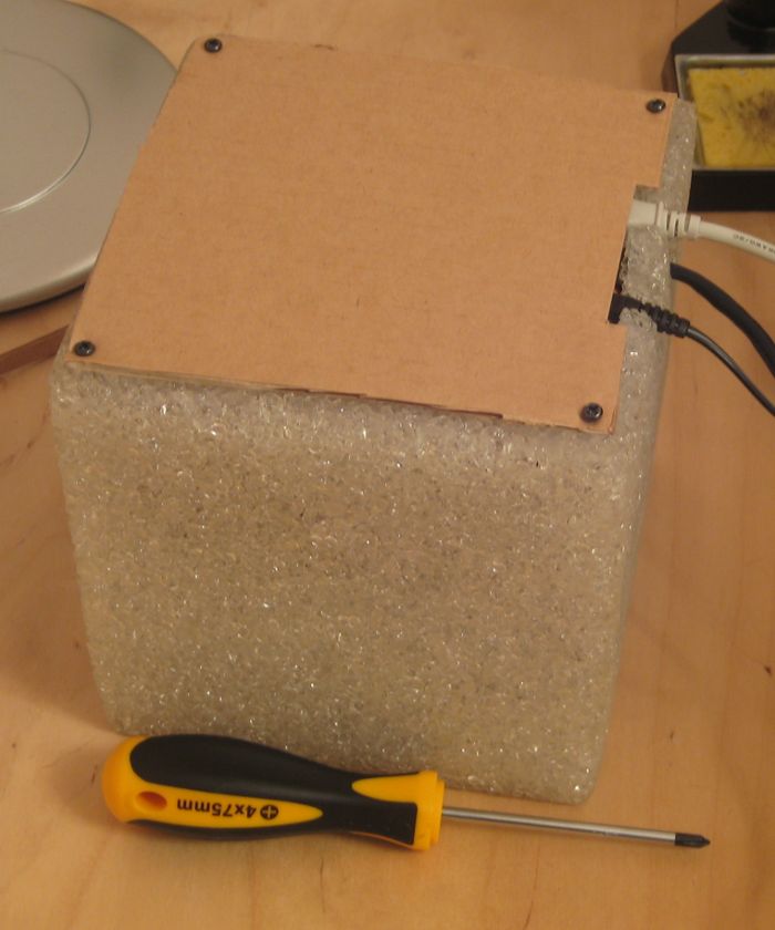
Now all the offal must be placed inside the cube. To make the glow more even, I confused the LED strips into a ball, fixed them with plastic clamps, and shoved a crumpled translucent plastic bag into the cube. For the lid, it was decided to use a square piece of
cardboard. Arduino is attached to it using double-sided tape.
Carefully close the lid and fix it on the 4 screws that used to hold the lamp's native filling
Integration with Team City
This is the system we use as a CI server. Now we need to make sure that on necessary events, through IP-broadcast, the server sends UDP packets that are understandable to the lamp. It would be nice to write a Java plug-in for Team City. I'll probably write it in the end. But now, so as not to
waste time studying the API, we’ll use the quick'n'dirty method: let’s have a script that once in X seconds will look at the Team City report web page and understand what state it is in.
The source code of the script is located there, next to the firmware. If you have Hudson, CruiseControl, yes anything - you can use a similar approach.
dress rehearsal
We create an intimate atmosphere for our lamp, make a simple project in Team City, cross our fingers, turn everything on and freeze with a feeling of complete satisfaction:


What happened and failed
It turned out to solve the problem: we have a lamp that shows the current state of the project.
In addition, the thing turned out to be completely independent and, if desired, it can notify you of different things: the level of traffic jams, the performance of a site, the presence of unread letters, etc.
It did not work out to make a completely simple device. Three wires protrude from the lamp. USB is clearly superfluous, but it was not possible to solve the power problem. Yes, and the food itself, maybe too much. After all, there is PoE (Power over Ethernet) technology. If you make more efforts, it seems to me that you can make
sure that only the twisted pair patch cord sticks out of the lamp.
The theme with USB-powered haunts me. Perhaps one of the experts can explain this behavior? I’ll tell you in advance what I tried to do to get around it:
- Add backup capacitors to Vin output
- Passed Vin through a separate voltage regulator, the output of which was applied to the +5 V contact of Arduino itself
- I tried the input voltage 7.5, 9 and 12 V
- Used a 1000 mA power supply
None of this helped. It is known that Arduino himself consumes no more than 50 mA; Ethernet Shield - 150 mA; one tape at 12 V - 45 mA. Any opinions?
And in general, how do you like the gadget?
UPD : Now, a person wrote on the store’s e-mail who apparently wrote his return address incorrectly - I can’t answer him, but he wrote the following:
didn’t forget the current-limiting resistors in the transistor bases ??? Without them, you can burn arduino ... Well, their absence can definitely be the reason for the increased current consumption, but with the transistor bases you shortened the port legs to the ground almost to the ground.
And he is right! And is it just as soon as I missed it? I thought that if there are resistors in the tape itself - everything is ok, but they are not in that part of the circuit. Thank you, good man!