April 12, 2010 at 14:12
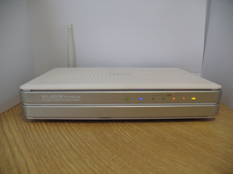
Hacking and modding ASUS WL500G Premium
So there was a time, and did a long time ago. Needless to say, this router is simply legendary and large communities of fans of this piece of iron have developed on the Internet . In this revision, the Lukey702 Soldering Station helped me a lot .
Let's start with hacking:
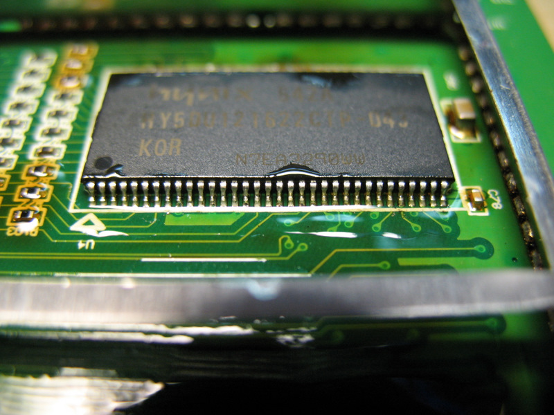
1. Installing 128MB memory. About it already on Habré is written, we will not stop, here is the result:
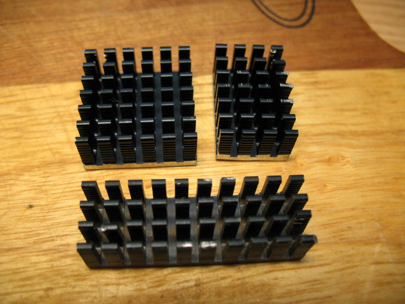
2. Installation of cooling radiators. We put the heatsinks on 2 chips, on Broadcom BCM5325EKQMG responsible for switching Fast Ethernet and on the Broadcom BCM4780 CPU (pictured is my first experimental router).

For this, I made the radiators myself, sawing Dremel so big:
To install (glue) the radiator, you need to apply a thermal interface to the chip (I always use KPT-8) and along the edges of the chip, with a toothpick “drop” a little bit of “Moment” glue (I use “Moment-Crystal”) and press the radiator . I do not recommend using ALSIL-5, as it does not provide such a good "thermal contact" as the usual KPT-8, and it is sold in stores 90% fake or already dried. I tried to buy this glue 3 times, I got “normal” only once, glued the necessary part and a week later the remaining glue dried, although it was tightly closed. I don’t get in touch with ALSIL-5 anymore and don’t want to get in touch, my method with Moment glue is much better!

To install the heat sink on the processor, you need to cut out the window in the cover-screen "Dremel" (sorry for the photo, it didn’t work right away, but I don’t really want to disassemble the device again)
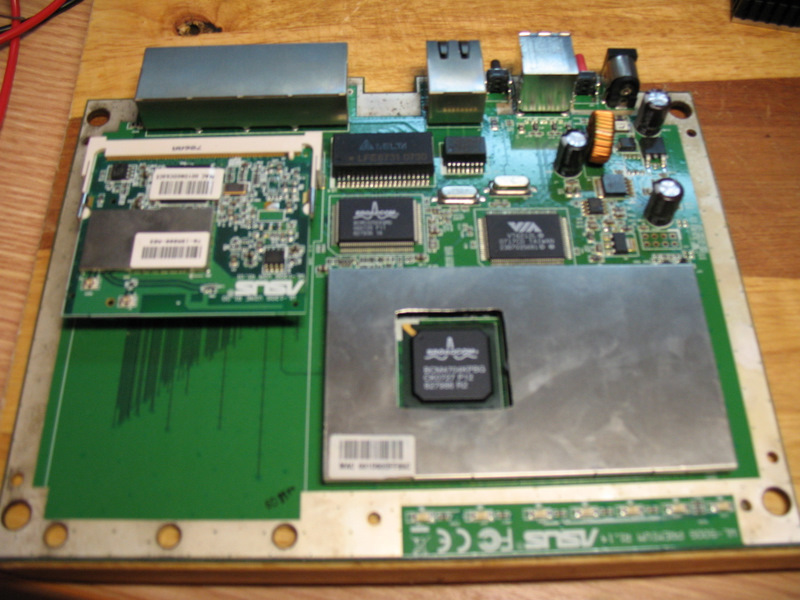
The radiators are glued, proceed to the next step ...
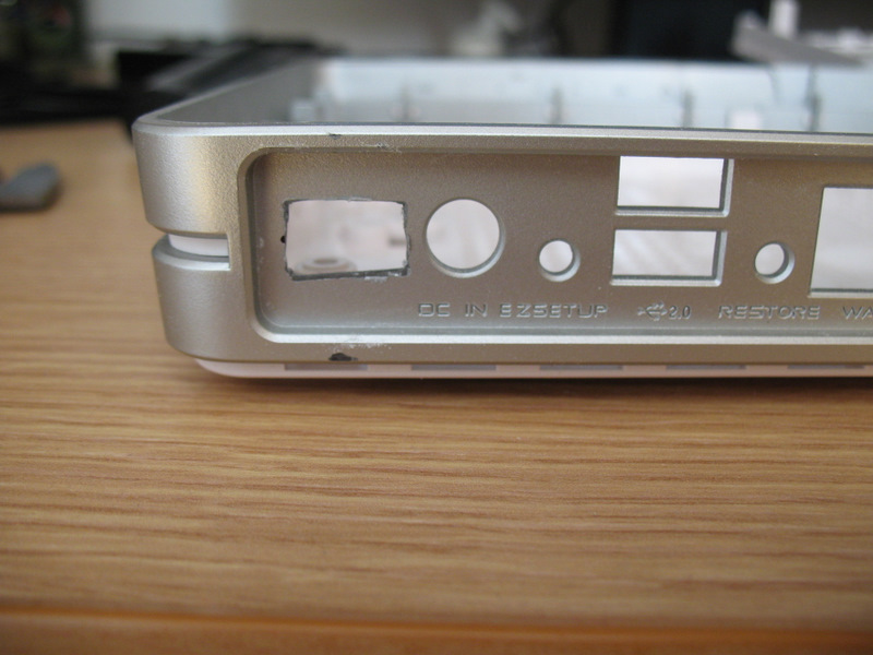
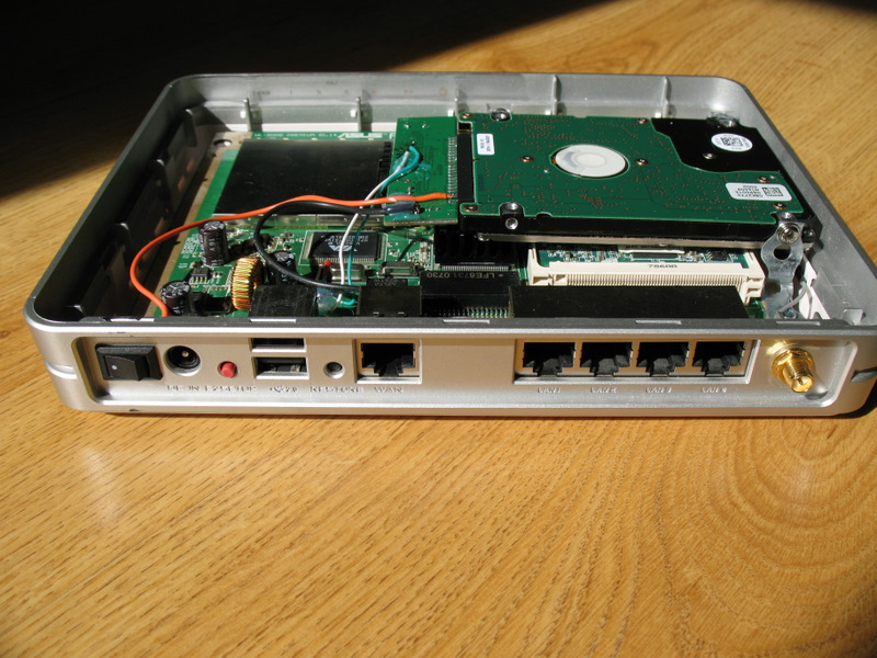
3. Cut out a hole for the HDD power switch in the case with "Dremel".
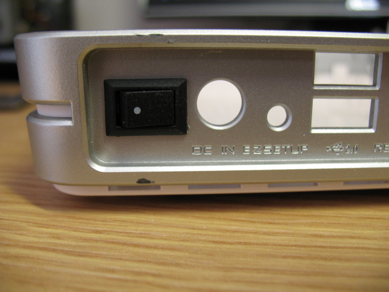
We put the switch
4. Installing the HDD inside the case.
We buy a USB-IDE / SATA adapter, or HDD BOX, disassemble, get a board, put it aside.
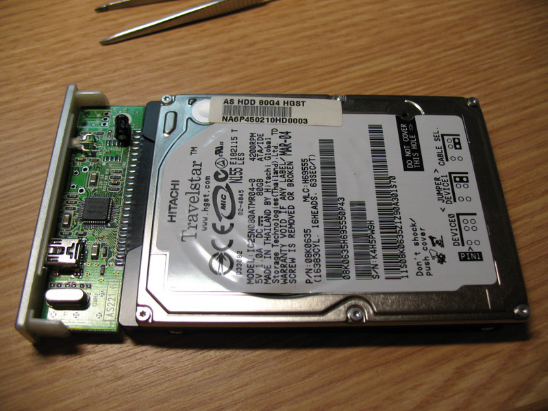
We buy a mounting tape in a hardware store, make brackets for a disk, try on installation in a case, and fasten everything with screws. Screwed to the "regular" holes on the board. ASUS engineers took care of us in advance and drilled holes in the board!

We solder the additional USB, the benefit of the PCI USB 2.0 Controller VIA VT6212 is 2 more undiluted free ports.

I unsoldered one for the disk.
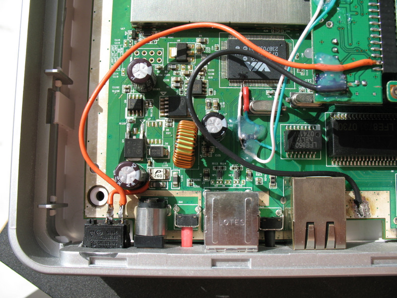
Under hotmelt adhesive, 2 SMD resistors in a 1206 by 15 kOhm housing, USB signal leads are pulled to ground.
We take + 5V power for the drive from the “polyswitch” to 2.6A, connected via a switch. Solder all the necessary wires to USB-IDE / SATA and get
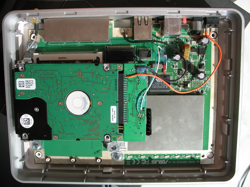
5. Install the cooler. We fasten the 6x6cm cooler to the cover with screws, the holes in the cover perfectly match the mounting holes of the cooler! We cut off the native connector, solder the BLS connector, tighten it into heat shrink (this is “mother”), solder PLS “pins” to the USB-IDE / SATA board (this is “father”). In the photo, the cooler is set to “blow”, it was subsequently turned upside down because the impeller abutted against an electrolytic capacitor mounted on the board. At the same time, we wrap the light guide with electrical tape in order to remove the parasitic illumination of the case from the inside by LEDs.

We have already started modding ...
6. We solder the dull red LEDs to multi-colored. They are needed in 1206 SMD cases, about 60 millikandels, so that the brightness is about the same. I took it: green on “POWER”, blue on “AIR”, native redheads left on “LAN”, yellow on “WAN”. It is better to solder the lights with two soldering irons at the same time, applying the sting to the contacts on both sides and shifting to the side, and even better with special forceps. The solder in the router is lead free and very refractory.

7. We cut off the “fake” antenna, the antenna itself occupies less than half the length of its body.
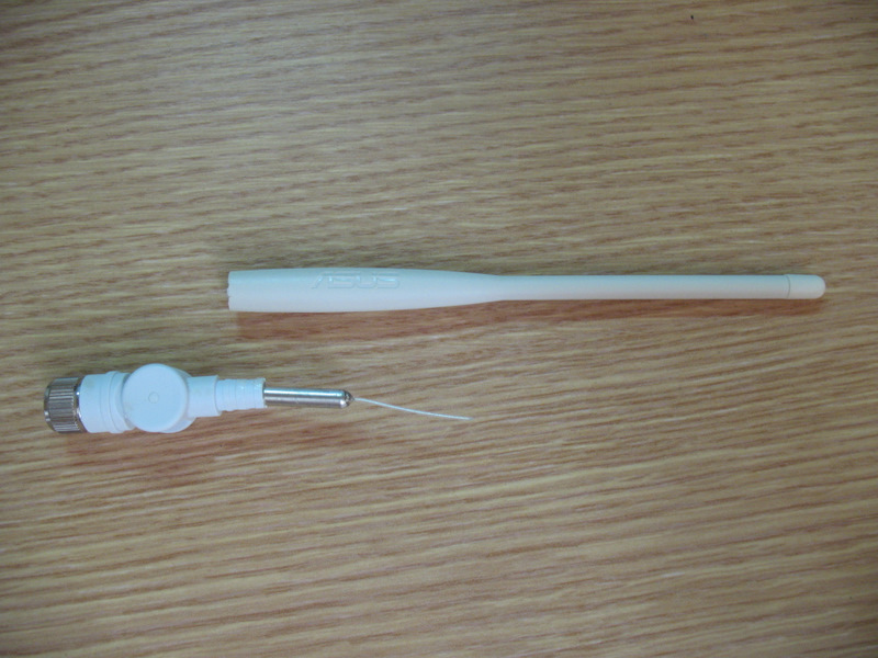
We cut off the cap, it is removed, you do not need to take it off, you just need to cut it off, cut out the middle part, glue the cap in the “joint”, we get a small neat antenna that no longer interferes.
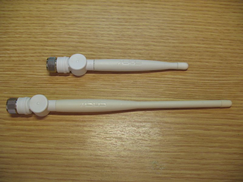
Before the final assembly, this turns out. We
collect everything and get such a handsome man.
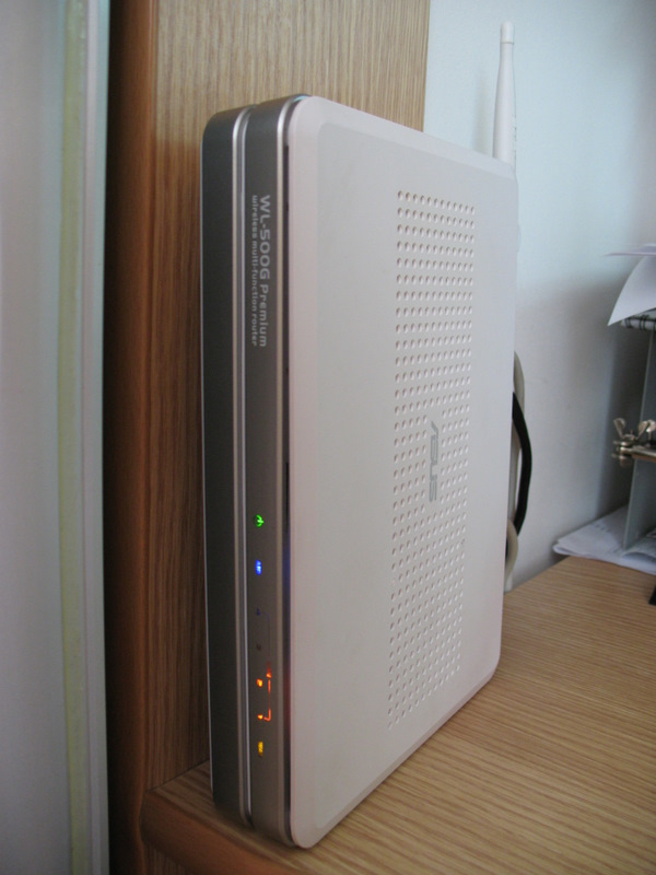
Next, we “overclock” the processor to 300 MHz (this is not exactly overclocking, this is its native frequency), install the necessary services on the router and enjoy life. I have installed “Dummy programs” , thanks to these guys and the community!
PS For whom this device does not work well or does not start at all, randomly blinking diodes, first of all, check the power supply !
Let's start with hacking:
1. Installing 128MB memory. About it already on Habré is written, we will not stop, here is the result:
2. Installation of cooling radiators. We put the heatsinks on 2 chips, on Broadcom BCM5325EKQMG responsible for switching Fast Ethernet and on the Broadcom BCM4780 CPU (pictured is my first experimental router).
For this, I made the radiators myself, sawing Dremel so big:
To install (glue) the radiator, you need to apply a thermal interface to the chip (I always use KPT-8) and along the edges of the chip, with a toothpick “drop” a little bit of “Moment” glue (I use “Moment-Crystal”) and press the radiator . I do not recommend using ALSIL-5, as it does not provide such a good "thermal contact" as the usual KPT-8, and it is sold in stores 90% fake or already dried. I tried to buy this glue 3 times, I got “normal” only once, glued the necessary part and a week later the remaining glue dried, although it was tightly closed. I don’t get in touch with ALSIL-5 anymore and don’t want to get in touch, my method with Moment glue is much better!
To install the heat sink on the processor, you need to cut out the window in the cover-screen "Dremel" (sorry for the photo, it didn’t work right away, but I don’t really want to disassemble the device again)
The radiators are glued, proceed to the next step ...
3. Cut out a hole for the HDD power switch in the case with "Dremel".
We put the switch
4. Installing the HDD inside the case.
We buy a USB-IDE / SATA adapter, or HDD BOX, disassemble, get a board, put it aside.
We buy a mounting tape in a hardware store, make brackets for a disk, try on installation in a case, and fasten everything with screws. Screwed to the "regular" holes on the board. ASUS engineers took care of us in advance and drilled holes in the board!
We solder the additional USB, the benefit of the PCI USB 2.0 Controller VIA VT6212 is 2 more undiluted free ports.
I unsoldered one for the disk.
Under hotmelt adhesive, 2 SMD resistors in a 1206 by 15 kOhm housing, USB signal leads are pulled to ground.
We take + 5V power for the drive from the “polyswitch” to 2.6A, connected via a switch. Solder all the necessary wires to USB-IDE / SATA and get
5. Install the cooler. We fasten the 6x6cm cooler to the cover with screws, the holes in the cover perfectly match the mounting holes of the cooler! We cut off the native connector, solder the BLS connector, tighten it into heat shrink (this is “mother”), solder PLS “pins” to the USB-IDE / SATA board (this is “father”). In the photo, the cooler is set to “blow”, it was subsequently turned upside down because the impeller abutted against an electrolytic capacitor mounted on the board. At the same time, we wrap the light guide with electrical tape in order to remove the parasitic illumination of the case from the inside by LEDs.
We have already started modding ...
6. We solder the dull red LEDs to multi-colored. They are needed in 1206 SMD cases, about 60 millikandels, so that the brightness is about the same. I took it: green on “POWER”, blue on “AIR”, native redheads left on “LAN”, yellow on “WAN”. It is better to solder the lights with two soldering irons at the same time, applying the sting to the contacts on both sides and shifting to the side, and even better with special forceps. The solder in the router is lead free and very refractory.
7. We cut off the “fake” antenna, the antenna itself occupies less than half the length of its body.
We cut off the cap, it is removed, you do not need to take it off, you just need to cut it off, cut out the middle part, glue the cap in the “joint”, we get a small neat antenna that no longer interferes.
Before the final assembly, this turns out. We
collect everything and get such a handsome man.
Next, we “overclock” the processor to 300 MHz (this is not exactly overclocking, this is its native frequency), install the necessary services on the router and enjoy life. I have installed “Dummy programs” , thanks to these guys and the community!
PS For whom this device does not work well or does not start at all, randomly blinking diodes, first of all, check the power supply !