Augmented reality glasses from the old Soviet calculator
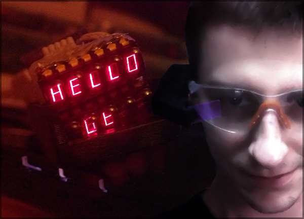
Glasses of augmented reality is unreal cool thing! The truth is still hard to say whether this is a necessary thing as a smartphone, or just an expensive toy. Consider an interesting project of smart glasses for professional use, which facilitate the work of an electrician / electronics engineer. Let's make it in the style of the good old DIY with arduines and 3d printers.
Anyone who has practiced a little electronics knows what a multimeter is and how to use it. Nothing too complicated - we take two probes, set the measurement mode, poke and watch the result on the display. Despite the simplicity, in professional practice there are often cases when there is a probe in each hand, and there is simply no place to put a measuring device and you have to exhaust in every possible way to attach it to anywhere. This makes a huge inconvenience in the work, and with due clumsiness and high voltages, also to bright fireworks.
Alain Mauer thought, why not show the result of measurements of a multimeter right before your eyes, using augmented reality technology like the one done in Google Glass.
He developed his own project of smart glasses, based on the Arduino Pro Micro controller, a small display with a diagonal of 0.66 inches (1.68 cm), as well as a bluetooth module.
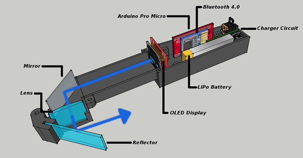
The device case is printed on a 3-d printer and all details are available for download on the project page .
However, as you may have guessed from the title of the article, there will not be a description of the assembly of parts according to the finished instructions, instead I will show how I assembled this device from what I found in my pile of electronic junk. And we start with a micro display.
In principle, the Chinese comrades sell such screens quite inexpensively, but the circus with Black Friday at that time made it clear that it would take a very long time to wait.
Therefore, having rummaged in the trash, I found the old Soviet electronics calculator B3-21 with quite good miniature eight-segment indicators.
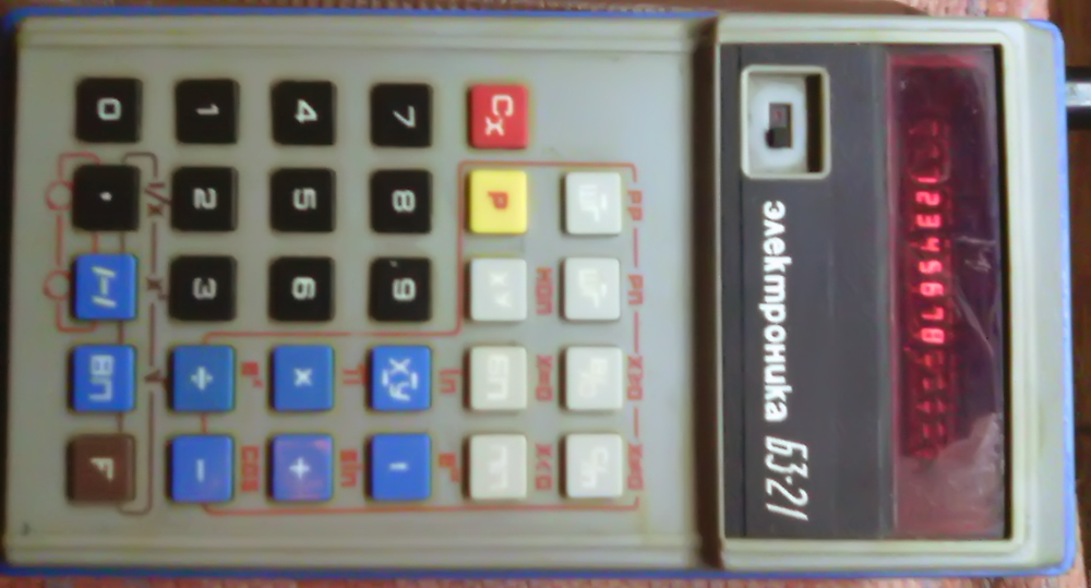
Stop! Hold your righteous anger and take your hands off the keyboard. I would not break such a rarity for the sake of indicators. A couple of years ago, I saved three such instances from the garbage. Two of them were more or less whole, I gave them to collectors. The latter was only a pitiful remnant in the form of a board with indicators, while the calculator’s brains themselves were located on another part, which the barbarians, along with the corps, shared somewhere.
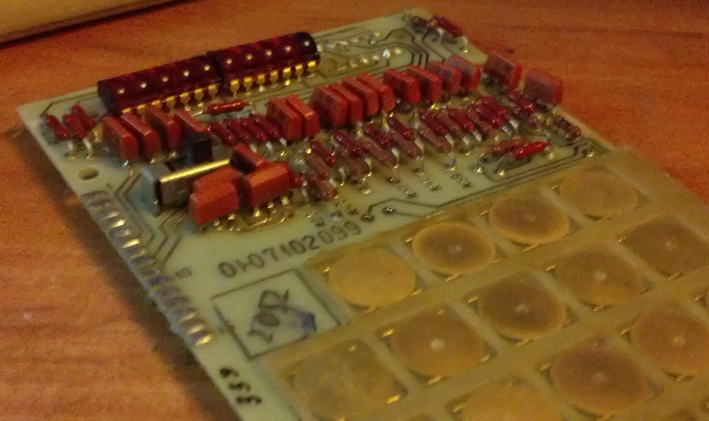
As can be seen from the photo, there were only three indicators in the calculator, and they were made in the DIP-14 package. Each indicator has five characters with seven segments in each + another dot. Carefully unsolder and plant on the breadboard. The design of the size goes quite a bit more of the microdisplay from the original project.
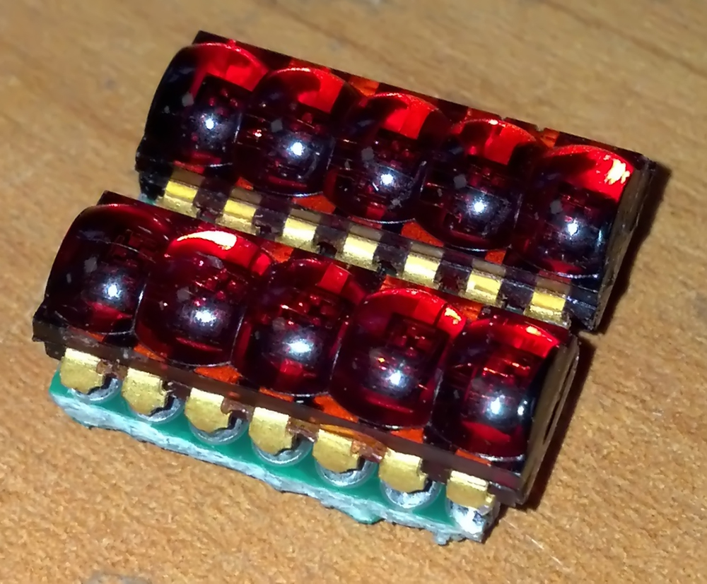
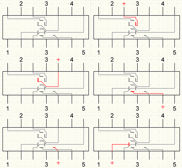
Since there is no documentation on these indicators during the day with fire, we use a little trick to determine the pinout. Many of the multimeters in dialing / resistance measurements give enough voltage to the probes to make the LEDs glow a little, or there are such indicators. Turning all the outputs in turn, we find the necessary anodes (+) and cathodes (-). The latter are labeled with the numbers responsible for each of the five characters.
Thus, to control two such indicators, you need a microcontroller and only 18 of its ports. Roll up the lip and use the shift registers 74HC595. Each of them has eight outputs, and only connects to the three ports of the controller. The simplest way to connect from the network:
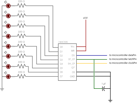
I added to the design of two of these in small packages. The first controls the segments, and the second controls the characters. There are more characters than register outputs, because the two extreme characters in the bottom row will not be used, which is basically not a problem, since I planned to display the measured value on the top line as digits, and for this, three characters are enough for this.
The code for displaying characters is a byte, each bit of which is responsible, in the case of the first register, for the segments being lit, and, in the case of the second, for the symbols being lit. Such bytes are also often represented in hexadecimal notation.
Illustrative example for indicator segments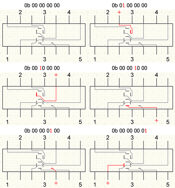
As a controller, I used the Chinese Arduino Nano. It is a little more than the Micro version and is also excellent in the original case.
We connect to arduinka and check the operation of indicators.
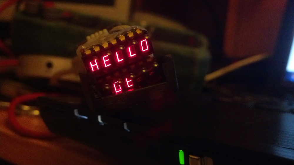
After a successful test, it is time to think about what this display will show.
In the original project, the author used the OWON B35T “smart” multimeter, which has a built-in Bluetooth interface and can send measurement results on it.
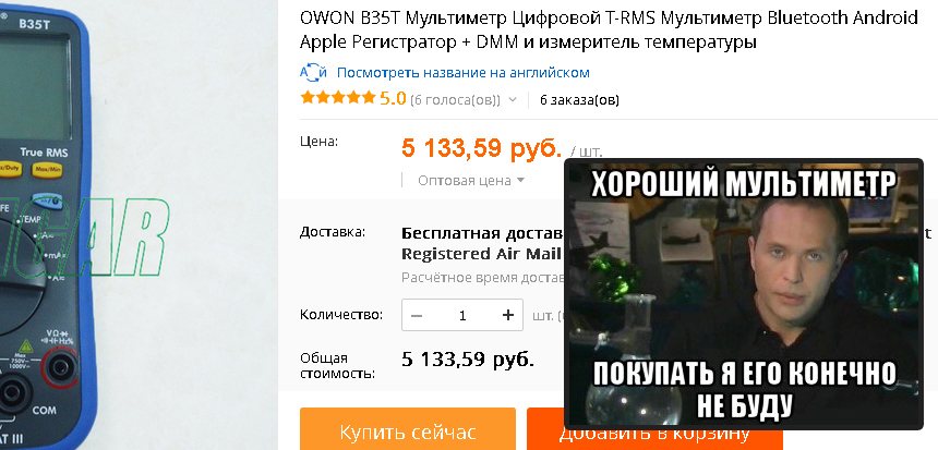
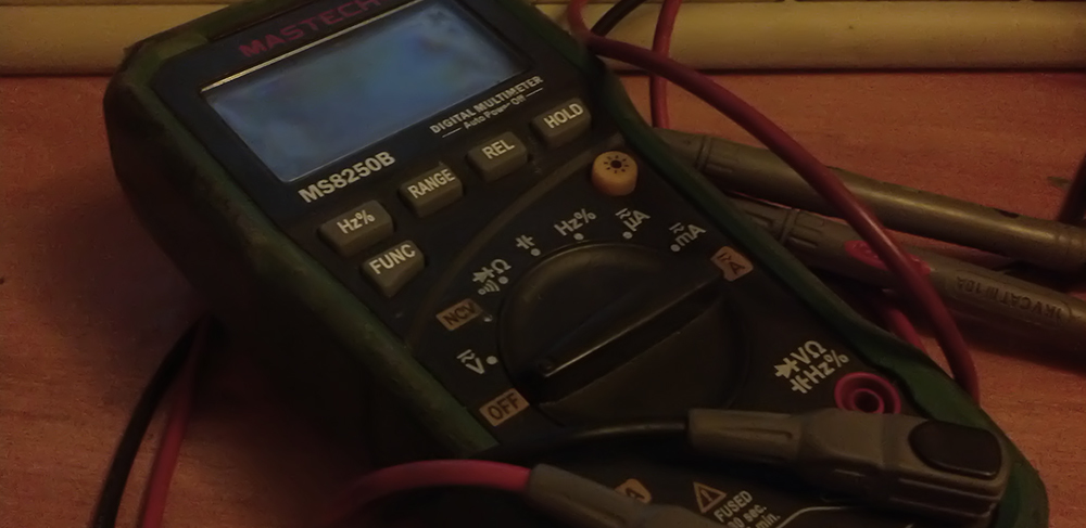
Instead of this slicker, we will pump the cheaper, battered in battles, the good old Mastech MS8250B, which nevertheless has a USB interface.
Reverse engineering this device and see that the interface is made on a separate board, which is optically isolated from the rest of the circuit. And here they used not the notorious optocouplers, but the real infrared pairs of light and photodiodes. The gap between them is such that you can certainly measure up to kilovolts without fear of burning your computer. You can see the CP2102 chip on the board, which is a UART → USB converter, which is a great success, since any Arduinka knows the UART protocol from the cradle.
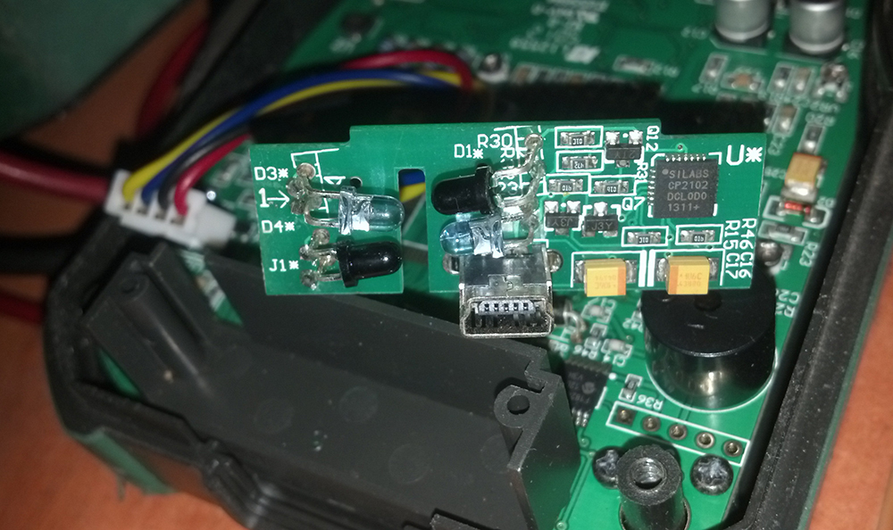
The principle of operation is simple and trivial, the CP2102 is powered by USB, the IR LED lights up at the same time, which lets the multimeter know that it is connected to a computer, after which the latter begins to blink merrily with its LED in response, thus sending measurement data . We connect this cartoon to the computer and use the ComPort Toolkit to see what it sends:
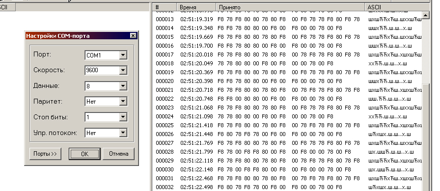
Yes, it seems like complete nonsense. Obviously, the Chinese comrades did not use the standard speed of 9600. Armed with a logic analyzer (Saleae-logic compatible) and look at the signal in more detail. Software from Saleae is so cool that it can automatically determine the speed of the UART along the length of the start bit.
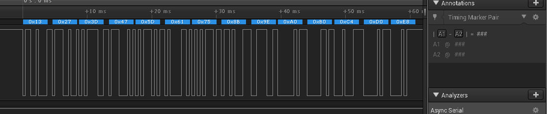
The analyzer clearly determined the speed in 2400. We set the correct speed in the terminal and look at the output by frantically clicking the multimeter modes to collect more different data.
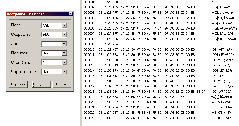
Well, some regularity has already appeared, although it is still not clear what he is sending.
hint
We draw attention to the senior digits of the numbers that make up the sequence 123456789ABCDE. They do not change even when switching modes of the device, and therefore are purely controlling in nature. The rest is data in some form.
I measured several different resistances, making a table for comparison.
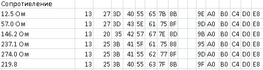
Having studied the table, I understood how the multimeter encodes the measurement data. You can think about this problem yourself, for the impatient here is the solution:
decision
Подсказка есть в первой части статьи, так как в мультиметре используются все те же сегментные символы для обозначения цифр, то и шлет он байты, описывающие какие сегменты активированы в шестнадцатиричной форме. Старшие разряды не несут информации, потому смотрим на младшие и одинаковые цифры в результатах измерения. Из этой таблицы становится ясно, что 0 например это 7D, а 2 это 5B. Таким образом, задача передачи еще более упрощается. Достаточно прочитать значения индикаторов мультиметра и зажечь наши в соответствии.
Подсказка есть в первой части статьи, так как в мультиметре используются все те же сегментные символы для обозначения цифр, то и шлет он байты, описывающие какие сегменты активированы в шестнадцатиричной форме. Старшие разряды не несут информации, потому смотрим на младшие и одинаковые цифры в результатах измерения. Из этой таблицы становится ясно, что 0 например это 7D, а 2 это 5B. Таким образом, задача передачи еще более упрощается. Достаточно прочитать значения индикаторов мультиметра и зажечь наши в соответствии.
It remains only to shove a controller into the multimeter case that will turn on the infrared LED, receive measurement data via the UART, and send it to the glasses. In this case, purely to test the technology, I put a large arduinka in there, since the little ones suddenly
run out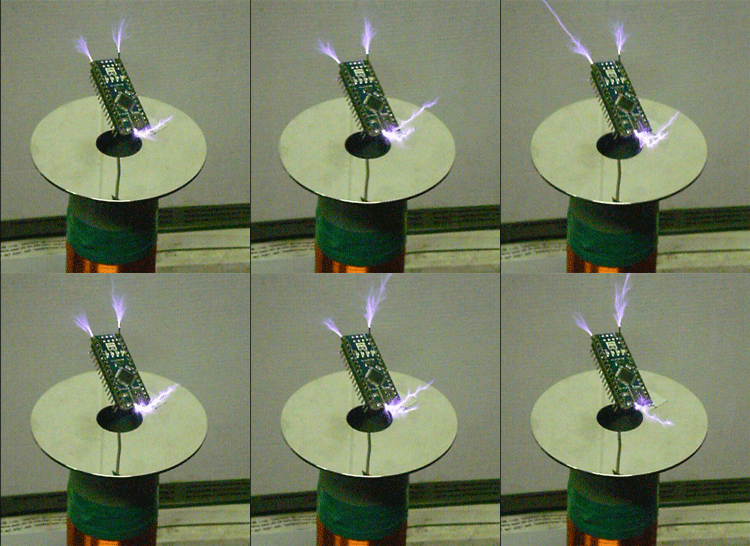
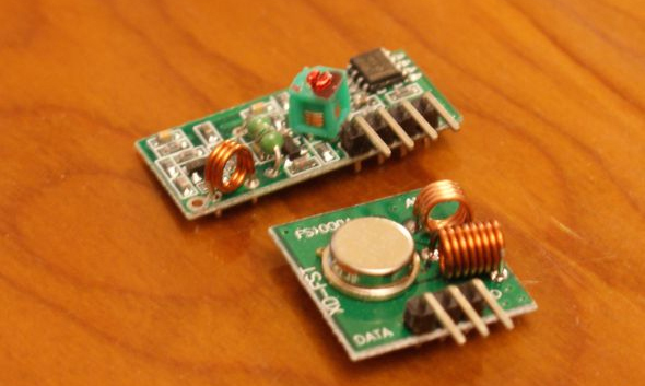
To connect the multimeter with glasses, I used cheap 433 MHz radio modules. Alas, this is the worst solution that you can think of, but this is the only thing that was at hand.
We assemble the display, controller, receiver and battery in a printed case
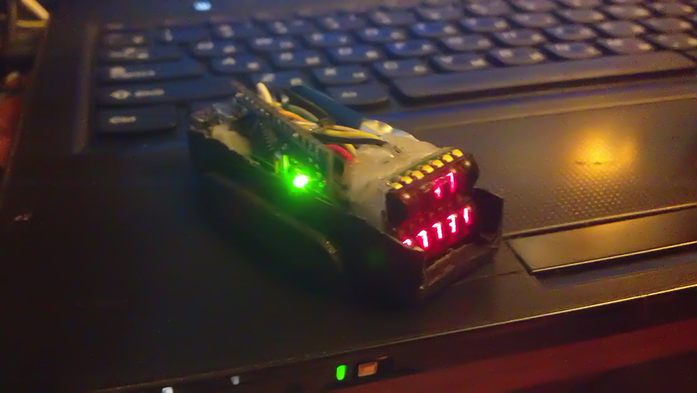
. We had to work with the optical part. Plastic mirror as the author in my area is not found. To wield a glass cutter, I am not a master, because despite all the superstitions, I broke a small mirror and ground a suitable fragment to the desired shape under a stream of water.
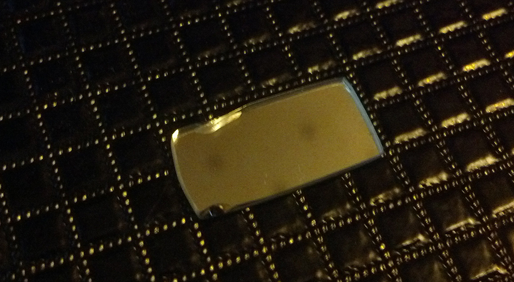
At this stage, I advise you to return to the beginning of the article and refresh the design of the device. The lens here plays a huge role - it focuses on the eye image from the display. From its type and position depends on how the focus of the eyes will be clearly visible numbers. Of course, I did not find the same lens, so I used the usual plastic one from a cheap monocular. In my case, I placed it between the mirror and the indicators, finding the best position in terms of focus. To make a reflector, I peeled the CD-ROM, wiped the data from it with a rag and just cut out a suitable piece. After assembly, we get the coveted device.
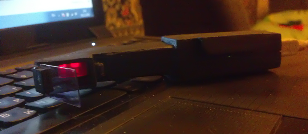
Due to the fact that the wrong lens is used, as well as the fact that the indicators are larger than the display in size, only four characters on the upper line can be seen on the reflector, and the lower line does not completely fall. In the photo, the camera transmits colors too brightly, in fact the numbers are much more faded.
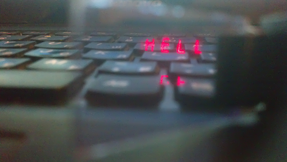
In general, the camera is quite problematic to take an image on the reflector, in addition, it always sees the numbers in focus, which of course is far from reality. Connect a multimeter and see how it works.
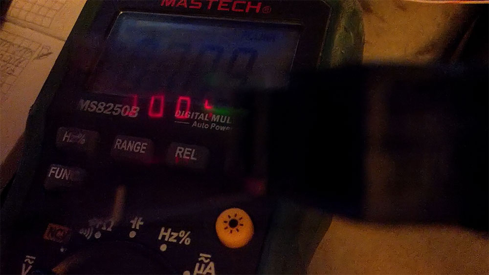
The camera is difficult to capture both lines, although the eye sees them. Working with the resulting device looks like this:
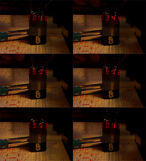
The measurement result is 6.73 volts. As we see, the engineers of the USSR who developed these LED indicators for some reason placed a point in such a not very comfortable position, which, however, again can be considered luck, since in the multimeter the point is completely to the left of the symbol. Well, however, this is a matter of habit.
Results
The device in my performance of course came out pretty kolkhoz, but even in this form its use was fascinating. Alas, the indicators from the old calculator turned out to be a mediocre version, since with normal lighting the numbers are almost invisible. Radio modules also do not advise: the transmitter will land the battery quickly, and the connection will still be so-so. Well, the main drawback, probably, of any augmented reality glasses is the focus. In order to have the effect that the image is superimposed over the object where the gaze is directed, proper focusing must be maintained. And the problem is that the eye constantly changes it, from which all the "magic" is lost.