Connect the joystick from Dendy to Raspberry pi
One day, after watching all kinds of “While everyone is playing,” I also wanted to play my Raspberry pi. And not just to play, but to play using a real device. Why in the passage of the metro for 150 rubles was bought a joystick from Dandy (well, not from dandy, but Shimbas Junior). Those who are interested in what came out of it can click on the button below. At the end of the article there will be a link to the proof.
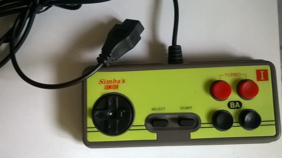
Our Chinese friends gathered it with a motto - there is no quality, but you hold on. Immediately, a native cable with a cross-section of 2 square meters of micron was discharged, and replaced with a cable from some industrial interface converter, inherited after the next commissioning operation, it just had 5 lived.
Before you make changes to the code, it was necessary to figure out how the gamepad itself works. The gamepad has a shift register. At the gamepad 5 wires - 2 - power, 3 information - Latch (Strobe), clock (Pulse) and data. When a logical unit is applied to the Latch, the state of the shift register inputs is saved, while at the output - data the button “A” is immediately available, and when the logical level changes on the clock line at the output - data, voltage levels corresponding to the state of the other seven buttons appear in a consistent way. The pressed button corresponds to - 0, not pressed - 1. And for the game everything is exactly the opposite, you need to do an inversion. The figure below shows a diagram of the gamepad.
Next came the choice of an emulator. The choice fell on an old fceu version 0.98.12, since it has excellent modularity and rather accurately emulates the console architecture, and it is written in C. This was followed by the choice of a library for working with GPIO, I chose bcm2835 from Mike McCauley, which is also written in C and has a good speed.
Since I am a noob in programming, I had to turn to one of the celebrities of the same “While everyone is playing”, with a request to comment on code sections. And poke his nose into those functions that are responsible for the transfer of the state of the buttons to the game. They explained to me in an accessible language, that yes how. And so, the input.c file is responsible for input emulation, and with it there will be major changes. There are several functions that are responsible for imitating a gamepad - FCEU_UpdateInput, ReadGP and DECLFW (4016), in fact, this is more important. In addition to input.c, I had to make changes to the files file.c and fceu.c. In the first case, there were errors in the file.c file, but this problem is googling, there is a patch for this file, and in the fceu.c file I added the initialization of the bcm2835 library to the int FCEUI_Initialize (void) function:
Before adding its header file
Now input.c, I also added the bcm2835 library header file (similar to fceu.c) and the <unistd.h> library header file, for working with usleep. Next, I announced the GPIO ports that will be involved:
In the void InitializeInput (void) function, I added the code in which I registered the operation mode of each GPIO port, and immediately reset the ports responsible for Latch (Strobe) and clock to 0.
Now to the functions:
And so DECLFW (4016) - is responsible for simulating the signal Latch (Strobe). As it was said, in order to read the state of the buttons it is necessary to apply for Latch - 1 for a while. There is a variable Laststrobe in which the last value written to this register is written. If Laststrobe was 0, then logical 1 is written, respectively, the GPIO pin, which is designated Latch, is also fed 1 and reset to 0 after 1 µs. And if Laststrobe was equal to 1, then this code section is ignored.
Well, now the joystick poll itself, void FCEU_UpdateInput (void) - this function reads data from the input drivers that were selected during emulator configuration, or when it is started by entering certain keys, for example - a gamepad, poverpad, a light gun, etc. ., all that could be connected to the console. In it, the bytes of the state of the buttons of the gamepads joy [0] ... joy [3] are formed, in an amount from 2 to 4, since it is possible to enable pribluda emulation to connect another 2 gamepads. Here in it there were major changes. Since I do not need to use the opportunity to work with 4 gamepads and receive data from other drivers, I threw out all the code and wrote my own:
And I immediately form two bytes, respectively, of the first and second joysticks. Since many games read the state of buttons from 2 ports at the same time, there is no concept of a priority port for them. But there are games for which such a concept exists - for example, everything is Mario, Kirby, Terminator 2, etc. That is, they read the state of the buttons only from the first port (in Mario for the first player, for the second only from the second), that is, from register 4016. It is also important to assign a zero value when calling this function, otherwise the previous value will be stored in them, and new will already be superimposed on them. In principle, it was possible to leave the byte for the second joystick equal to zero, but I made it so that there was an opportunity to play Mario together.
ReadGP - it already selects bits from bytes joy [0] ... joy [3], and the variable ret returns the state of a particular button to the game at the moment, the button number is set by the variable joy_readbit [w], where w is the port number of the joystick first or second. But in this function I did not make any changes. Left as is.
To compile successfully, in the Makefile (formed after the Configure command), which is located in the src directory, add -lbcm2835 -lm -lrt to the place where the dependencies on the libraries are written. Line:
And in general, everything worked. I left a reserve, if I suddenly decided to buy a second joystick to play together in the same tanchiki.
Our Chinese friends gathered it with a motto - there is no quality, but you hold on. Immediately, a native cable with a cross-section of 2 square meters of micron was discharged, and replaced with a cable from some industrial interface converter, inherited after the next commissioning operation, it just had 5 lived.
Before you make changes to the code, it was necessary to figure out how the gamepad itself works. The gamepad has a shift register. At the gamepad 5 wires - 2 - power, 3 information - Latch (Strobe), clock (Pulse) and data. When a logical unit is applied to the Latch, the state of the shift register inputs is saved, while at the output - data the button “A” is immediately available, and when the logical level changes on the clock line at the output - data, voltage levels corresponding to the state of the other seven buttons appear in a consistent way. The pressed button corresponds to - 0, not pressed - 1. And for the game everything is exactly the opposite, you need to do an inversion. The figure below shows a diagram of the gamepad.
Next came the choice of an emulator. The choice fell on an old fceu version 0.98.12, since it has excellent modularity and rather accurately emulates the console architecture, and it is written in C. This was followed by the choice of a library for working with GPIO, I chose bcm2835 from Mike McCauley, which is also written in C and has a good speed.
Since I am a noob in programming, I had to turn to one of the celebrities of the same “While everyone is playing”, with a request to comment on code sections. And poke his nose into those functions that are responsible for the transfer of the state of the buttons to the game. They explained to me in an accessible language, that yes how. And so, the input.c file is responsible for input emulation, and with it there will be major changes. There are several functions that are responsible for imitating a gamepad - FCEU_UpdateInput, ReadGP and DECLFW (4016), in fact, this is more important. In addition to input.c, I had to make changes to the files file.c and fceu.c. In the first case, there were errors in the file.c file, but this problem is googling, there is a patch for this file, and in the fceu.c file I added the initialization of the bcm2835 library to the int FCEUI_Initialize (void) function:
bcm2835_init();Before adding its header file
#include<bcm2835.h>Now input.c, I also added the bcm2835 library header file (similar to fceu.c) and the <unistd.h> library header file, for working with usleep. Next, I announced the GPIO ports that will be involved:
#define LATCH RPI_V2_GPIO_P1_11#define CLK RPI_V2_GPIO_P1_13#define DATA RPI_V2_GPIO_P1_15In the void InitializeInput (void) function, I added the code in which I registered the operation mode of each GPIO port, and immediately reset the ports responsible for Latch (Strobe) and clock to 0.
        bcm2835_gpio_fsel(LATCH, BCM2835_GPIO_FSEL_OUTP);
	bcm2835_gpio_fsel(CLK, BCM2835_GPIO_FSEL_OUTP);
	bcm2835_gpio_fsel(DATA, BCM2835_GPIO_FSEL_INPT);
	bcm2835_gpio_set_pud(DATA, BCM2835_GPIO_PUD_UP);
	bcm2835_gpio_write(CLK, LOW);
	bcm2835_gpio_write(LATCH, LOW);
Now to the functions:
And so DECLFW (4016) - is responsible for simulating the signal Latch (Strobe). As it was said, in order to read the state of the buttons it is necessary to apply for Latch - 1 for a while. There is a variable Laststrobe in which the last value written to this register is written. If Laststrobe was 0, then logical 1 is written, respectively, the GPIO pin, which is designated Latch, is also fed 1 and reset to 0 after 1 µs. And if Laststrobe was equal to 1, then this code section is ignored.
staticDECLFW(B4016){
	if (FCExp)
	if (FCExp->Write)
	FCExp->Write(V & 7);
	if (JPorts[0]->Write)
	JPorts[0]->Write(V & 1);
	if(JPorts[1]->Write)
        JPorts[1]->Write(V&1);
        if((LastStrobe&1) && (!(V&1)))
        {
	 /* This strobe code is just for convenience.  If it were
	    with the code in input / *.c, it would more accurately represent
	    what's really going on.  But who wants accuracy? ;)
	    Seriously, though, this shouldn't be a problem.
	 */if(JPorts[0]->Strobe)
	  JPorts[0]->Strobe(0);
	 	if(JPorts[1]->Strobe)
		JPorts[1]->Strobe(1);
	 if(FCExp)
	  if(FCExp->Strobe)
	   FCExp->Strobe();
	 }
	if (LastStrobe==0)
		{
		bcm2835_gpio_write(LATCH, HIGH);
		usleep(1);
		bcm2835_gpio_write(LATCH, LOW);
		}
	LastStrobe=V&0x1;
}
Well, now the joystick poll itself, void FCEU_UpdateInput (void) - this function reads data from the input drivers that were selected during emulator configuration, or when it is started by entering certain keys, for example - a gamepad, poverpad, a light gun, etc. ., all that could be connected to the console. In it, the bytes of the state of the buttons of the gamepads joy [0] ... joy [3] are formed, in an amount from 2 to 4, since it is possible to enable pribluda emulation to connect another 2 gamepads. Here in it there were major changes. Since I do not need to use the opportunity to work with 4 gamepads and receive data from other drivers, I threw out all the code and wrote my own:
    joy[0] = 0;
    joy[1] = 0;
    for (i = 0; i <= 7; i++)
	{
		joy[0] ^= bcm2835_gpio_lev(DATA) << i;
		joy[0] ^= (1 << i);
		joy[1] ^= bcm2835_gpio_lev(DATA) << i;
		joy[1] ^= (1 << i);
		bcm2835_gpio_write(CLK, HIGH);
		usleep(1);
		bcm2835_gpio_write(CLK, LOW);
		usleep(1);
	}
And I immediately form two bytes, respectively, of the first and second joysticks. Since many games read the state of buttons from 2 ports at the same time, there is no concept of a priority port for them. But there are games for which such a concept exists - for example, everything is Mario, Kirby, Terminator 2, etc. That is, they read the state of the buttons only from the first port (in Mario for the first player, for the second only from the second), that is, from register 4016. It is also important to assign a zero value when calling this function, otherwise the previous value will be stored in them, and new will already be superimposed on them. In principle, it was possible to leave the byte for the second joystick equal to zero, but I made it so that there was an opportunity to play Mario together.
ReadGP - it already selects bits from bytes joy [0] ... joy [3], and the variable ret returns the state of a particular button to the game at the moment, the button number is set by the variable joy_readbit [w], where w is the port number of the joystick first or second. But in this function I did not make any changes. Left as is.
To compile successfully, in the Makefile (formed after the Configure command), which is located in the src directory, add -lbcm2835 -lm -lrt to the place where the dependencies on the libraries are written. Line:
LIBS =And in general, everything worked. I left a reserve, if I suddenly decided to buy a second joystick to play together in the same tanchiki.
" Link to proof
" Used data from the site
"Special thanks to this person who helped to understand the code of the emulator