50 shades of stub * ADC and ADC with Microchip Microcontroller computer
- POIs - Peripherals Independent of the Core in Microchip microcontrollers, also known as CIP - Core Independent Peripheral.
Part 3
Previous articles [ 1 ] and [ 2 ] dealt with such parts of the (PNC) Microchip Independent Microcontroller (MC) Core Peripherals such as configurable logic cells and I / O ports with a new useful current limiting function.
Now consider the Analog-to-Digital Converter (ADC) and in particular the new ADC with post-calculator. As you probably already used to, new features of the periphery can help in the implementation of specific functions and simplify the code under the PIC microcontrollers.
Unlike the previous parts, this one will have a little more theory and a few less examples.
Content
- Overview of ADC capabilities
- Trigger trigger
- VHD, CVD, Double conversion
- Post-calculator, filtering, averaging
- Configuration Examples
- Autostart, filtering
- Autostart, CVD, averaging, interruption compared to thresholds
- Autostart, Differential CVD, Conversion Series, Averaging
- Results
Overview of ADC capabilities
ADC with full confidence can be called Peripheral Independent of the Core, since the ADC has a clocking option from the built-in RC generator and can perform the conversion in the Sleep energy conservation mode. But independence is not limited to this. Many PIC16F1xxx families have an ADC with the possibility of starting on events, and completely new PIC16F188xx families have also received a post-calculator.
Consider the possibilities of the ADC for example MK family PIC16F18855 / 75
ADC controllers of this family has:
- 8-bit Acquisition Timer
- Capacitive Voltage Divider (CVD) hardware support:
- 8-bit precharge timer
- Array of capacitors adjusting the capacity of the water economy department
- Guard Ring Output Driver
- Automatic repeat and sequencing:
- automated double conversion for CVD
- Two sets of result registers (result and previous result)
- Auto transform trigger
- Internal retrigger
- Possibilities of the calculator:
- Averaging and Low Pass Filter
- Comparison with the reference value
- 2-level threshold comparison
- Selectable interrupts
ADC with a post-calculator consists of several blocks (Fig. 1):

Fig. 1. The structure of the ADC with the computer in the PIC16F18855 family.
Trigger trigger ADC
Gone are the days when to start ADC measurement it was necessary to “manually” set the bit. Now, the ADC can be launched by the following events:
- external input;
- timers triggering (general purpose and SMT - 24-bit signal measurement timers);
- output of the comparison module and PWM;
- operation of the comparator;
- state change of inputs configured as interrupt due to state change;
- output logic cells;
- reading the measurement result of the ADC;
- change the channel number of the ADC.
VHR and CVD
The sampling / storage unit (VHR) received additional capabilities, mainly related to simplifying the determination of the capacity of the ADC connected to the input. First of all it helps in creating interfaces with capacitive (touch) buttons.
Microchip offers to determine the capacitance of the sensor using a capacitive voltage divider (Capacitive Voltage Divider, CVD).
The essence of the method is as follows. In the first step (see Fig. 2), the sensor input is connected to the "ground" (its capacity is discharged), and the ADC channel to the supply voltage, the capacity of the water economy department is charged.
Then the sensor input is connected to the VHD ADC, the charge is redistributed between the capacitance of the sensor and the VHD capacity. Then, the voltage measurement at the storage facility tank is measured.
| CVD entry control | CVD waveform |
|---|---|
 |  |
Fig. 2. Diagrams explaining capacitance measurement using a capacitive voltage divider.
Touching the sensor will change its capacitance, which means we will fix different steady-state values of the voltage at the storage facility capacitor.
To reduce the effect of induced noise on the sensor and / or operator, a differential CVD is used, consisting of two consecutive measurements using CVD, but in the second stage we invert the charges on the sensor and the water economy department (we charge the sensor to the supply voltage, and discharge the water consumption device, see .3)

Fig.3. Signal diagram with differential CVD.
Details about the capacitive sensors, the method of differential CVD and control of the protective conductor can be read by reference [2].
The new ADC with post calculator for support and automation of CVD has the following functions:
- precharge timer
- charge sequence control (desired polarity), measurement start;
- connection of additional internal tanks to the water economy department;
- two consecutive measurements;
- calculating the difference between two measured values;
- driver control "protective ring" (guard ring).
Thus, the ADC in automatic mode can perform a differential CVD and provide us with the finished result.
Post-Calculator Functions
The post calculator performs several functions.
Filtration
The ADC module can operate in one of five modes:
Basic mode. In this mode, the ADC can make one or two measurements, after each can be set interrupt flag.
Accumulation. For each measurement, the result is added to the battery and the measurement counter is incremented.
Averaging For each measurement, the result is added to the battery and the measurement counter is incremented. Upon reaching the specified number of repetitions, the result is divided and entered into the comparison module, and the next measurement will reset the counter to 1 and the battery value will be replaced with the result of the first measurement.
Queuing averaging. By launching the ADC, the battery and the measurement counter are cleaned and a series of measurements is performed a specified number of times, after which the result is divided and sent to the comparison module.
Low Pass Filter. Each measured value passes through the low-pass filter. Upon completion of a specified number of measurements, the result falls into the comparison module.
Error calculation
Upon completion of each calculation, the result is recorded until the end of the next measurement. It also calculates the difference between:
- current and previous measurement (first derivative of a single measurement);
- two results in CVD measurement mode (differential CVD is calculated);
- current result and constant (setpoint);
- current result and filtered value;
- current and previous filtered values (the first derivative of the filtered result);
- filtered value and constant (setpoint).
If you do not need to calculate the difference, you can choose to calculate the difference between a constant equal to zero.
Comparison with thresholds
The result of the error calculation is compared with the upper and lower thresholds. Additionally, an interrupt can be generated if:
- the error is less than the lower threshold;
- the error is greater than or equal to the lower threshold;
- the error lies between the thresholds;
- error outside the thresholds;
- the error is less than or equal to the upper threshold;
- error greater than the upper threshold;
- forming an interrupt regardless of the result of comparison with thresholds (this mode can be useful for fixing the very fact of comparison, that is, when, for example, you need to obtain filtering / averaging data after N-measurements, and not an interruption after each measurement).
ADC Configuration Examples
Autostart, Filtering
This example shows the ADC configuration in the Mplab Code Configurator (MCC) plugin for the following actions:
- Timer2 timer is set to fire once per 1 ms;
- The ADC is triggered by a timer. The ADC performs the pre-sampling and measurement, the result falls into the filter. After accumulation of 32 filtered measurements, a shift by 5 bits (division by 32) is made and an interrupt request is issued.
The program only needs to read the register filtered value from the interrupt.

Fig. 4. ADC settings with a calculator.

Fig. 5. Read raw and filtered data from the ADC.
Autostart, CVD, averaging, interruption compared to thresholds
This example is based on the implementation of the “ fast creation of a capacitive sensor ” from microchip.wikidot.com [5].
The following configuration is selected:
- Timer2 timer is set to fire every 10ms
- The ADC is triggered by the operation of the Timer 2 timer. The ADC measures by the CVD method and calculates the average value of 32 measurements. After performing 32 measurements and accumulating the result, the division by 32 (shift by 5) is performed, and if the total value lies outside the threshold values, then an interrupt request is generated, thus a “touch” and “release” of the touch button is reported (actually in this example, the interruption is generated every time, since the button is either pressed or not and does not have intermediate states))

Fig. 6. ADC settings for CVD.
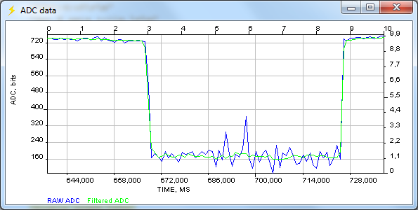
Fig.7. Reaction to touch the touch button with a single CVD.
Setting the threshold can give us an interruption not for each measurement / series of measurements with filtering, but at the touch of a “button”.
Autostart, Differential CVD, Conversion Series, Averaging
This example uses the following peripheral configuration:
- Timer2 timer is set to fire every 10ms
- The ADC is triggered by the timer triggering (see Figure 8, item 1). The ADC performs consecutive measurements by the differential CVD method (p.2) with a change in polarity (p.3), calculates the derivative (the difference between the 2nd CVD) (p.4), the ADC is set to calculate the average value (p.5) 32- x measurements (p.6). After performing 32 pairs of measurements and accumulating the result, the division by 32 (p.7) and the interrupt request (p.8) are performed, successive measurements are stopped (p.9) until the next trigger trigger (Timer2)
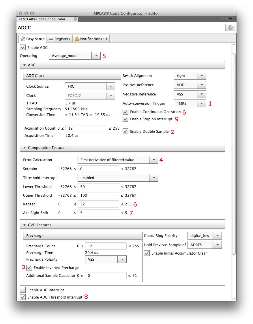
Fig. 8. ADC settings for the differential CVD option.

Fig. 9, Chart at the input of a differential CVD sensor
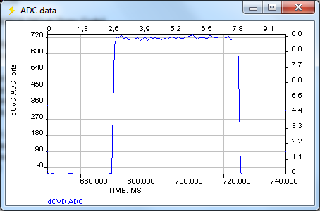
Fig.10. Touch Response with Differential CVD
From a comparison of CVD (Fig. 7) and differential CVD (Fig. 10), it is clear that the second one is distinguished by a more “pure” signal with a larger amplitude.
The entire described sequence of actions is carried out fully automatically and independently of the core - at this time, the MC can perform some other actions or be in the Sleep micro-consumption mode. By interruption, it remains to read the averaged value of the measurement result.
Results
We looked at another part of the Peripheral Independent of the Core - the ADC with the computer in Microchip microcontrollers. Some features, such as triggering on a trigger, or CVD are present in many PIC16F1xxx families, but a new “feature” - ADCC (ADC with a calculator) appeared in the PIC16F188xx family (PIC16F18855, etc.).
The periphery independent of the core is interesting in and of itself, but the possibility of synthesizing functional units, i.e. sharing of several peripheral modules for solving specific tasks. In this case, the clock frequency, speed, and bit depth of the core go into the background - the hardware performs specialized functions, and the core deals with software support for the product.
PS
Question to the readers. Is it worth it to spread the source code to the examples for some specific (cheap) demo board or from the descriptions and so everything is clear and code examples are not needed?
Literature:
- Configurable Logic Cells in PIC Controllers
- 50 shades of stub. I / O Ports
- Technology mTouch (tm). Creating capacitive keyboards, sensors and screens.
- PIC16 (L) F18855 / 75 Data Sheet. www.microchip.com