Testing multimeters and measurement errors
A study of the work of digital multimeters in the mode of an alternating current voltmeter , and a switch instrument. In normal and abnormal modes, on currents of various shapes - both of symmetrical polarity, and in the presence of a constant component.
Content of publication:
- Description of the instruments used, and their initial calibration
- Test for sinusoidal current of various frequencies
- Rectangular current test
- DC Rect Current Test
- Test with arbitrary waveforms, incl. pulsed
- Significant conclusion
- Voting
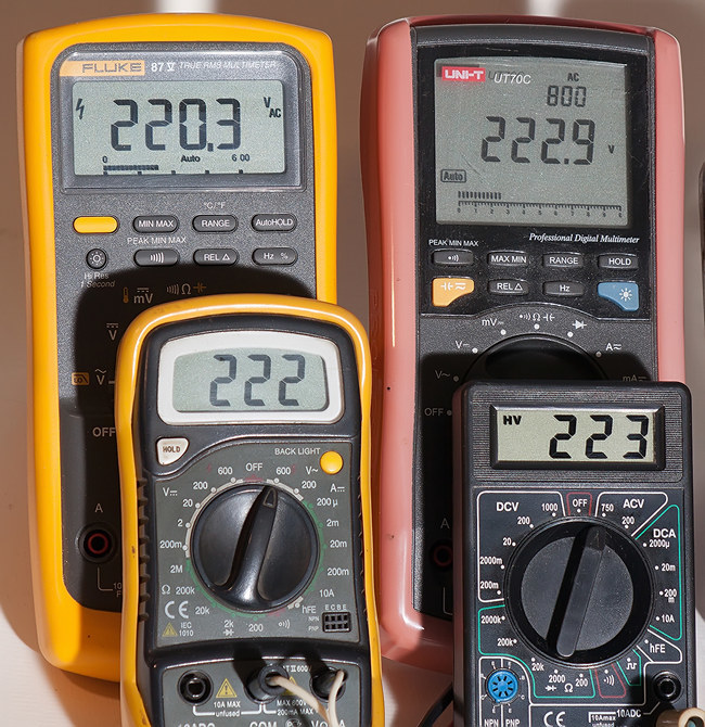
The list of experimental devices, all of them are connected in parallel: The
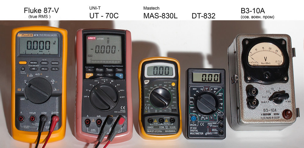
Fluke 87-V is a high-quality automatic multimeter capable of calculating the effective (rms) value of “true rms” of measured currents and voltages.
UT-70C - workhorse, dragged everywhere and everywhere. Released by the popular firm Uni-T, also automatic, but not “true rms”.
And the main characters of the study are the low-cost MAS-830L device from Mastech, and the completely rootless DT-832, which are usually filled with buckets for delivery. I rented them from different places to avoid possible glitches of a specific single instance.
Passport data of these devices per AC. stress
Fluke 87-V
Переменное напряжение 0.1 мВ — 1000 В
Разрешающая способность 1 мВ
Частоты до 20 кГц
Заявленная точность 0.7 % или 2 ед. мл. разряда
UT-70C
Переменное напряжение до 1000 В
Разрешающая способность 1 мВ
Частоты 40 — 400 Гц
Заявленная точность 1.5 % или 4 ед. мл. разряда
Mastech M830L
Переменное напряжение 0,1 В — 600 В
Разрешающая способность 10 мВ
Частоты 40 — 400 Гц
Заявленная точность 0.5 % или 2 ед. мл. разряда
DT 832
Переменное напряжение 0,1 В — 750 В
Разрешающая способность 0.1 В
Частоты 40 — 400 Гц
Заявленная точность 1.2 % или 10 ед. мл. разряда
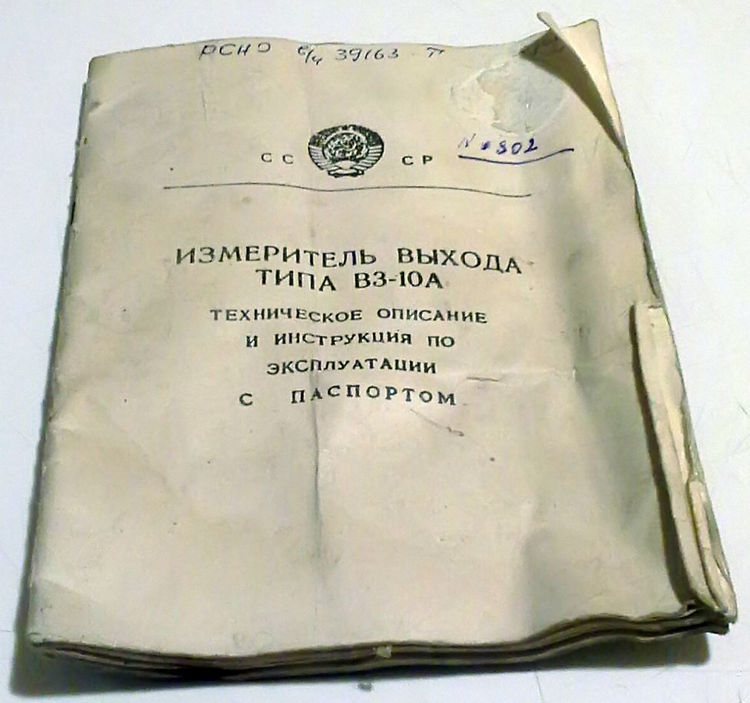
A switch-type voltmeter of alternating current B3-10A of Soviet production, released in 1969, also participates in the experiments . This is a good quality device. This copy slightly under-reads a few percent, but this will be repaired over time. In tests, it is used at the “3v” measurement limit.
More information about the voltmeter V3-10A can be found here.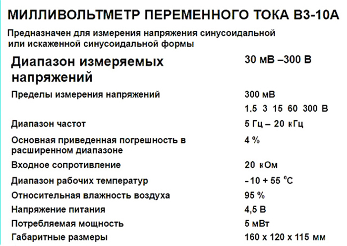
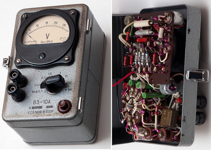
На принципиальной схеме цветом отмечено прохождение сигнала режиме измерения «3v».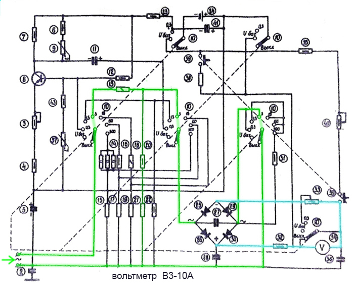
Как видите это обычный вольтметр с диодным выпрямителем. Правда сделан очень надежно, с применением высококачественных компонентов.
И данный экземпляр действительно с военки:
На принципиальной схеме цветом отмечено прохождение сигнала режиме измерения «3v».
Как видите это обычный вольтметр с диодным выпрямителем. Правда сделан очень надежно, с применением высококачественных компонентов.
И данный экземпляр действительно с военки:
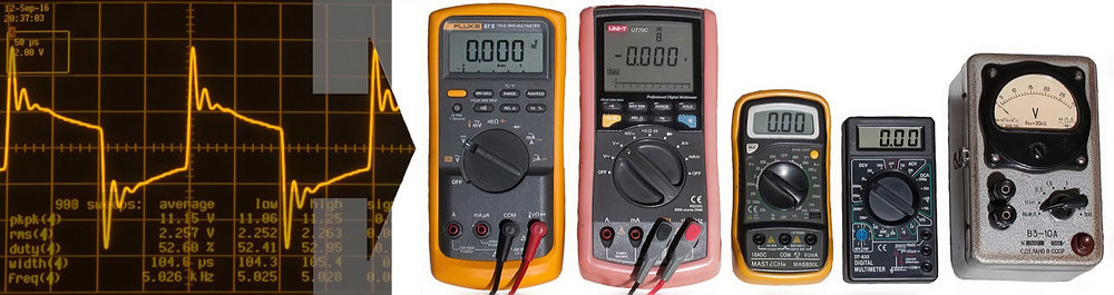
A visual monitor of the signals fed to the devices will be using a Lecroy 9354TM digital oscilloscope. It is also shaggy's, but it still works fine.
Oscilloscope appearance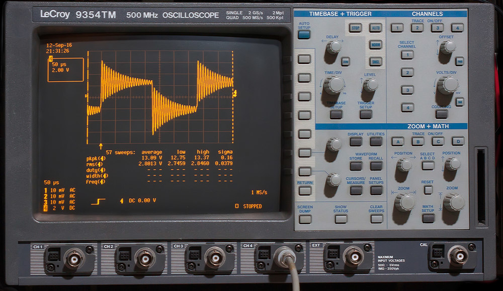
Under the waveform of the signal is the statistics of its parameters. The most interesting for this study are those that are highlighted in the photo:
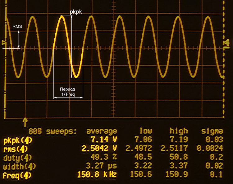
pkpk - full amplitude swing of the
RMS signal - root mean square
freq - frequency of the signal under study, or its pulses
In the average column, we observe the average value of the parameter, low and high - min. and max its values within the sample, sigma is the standard deviation. We will use only the data from the column average .
Calibration
We supply on digital multimeters 220 v from the socket. The switch voltmeter is disabled for now. he has not yet received post-purchase prophylaxis.
Also let's calibrate on the constant, including let's see what the gauge shows. Serving 2.5 v from the power supply. The oscilloscope is a bit overpriced - as it turned out compared to fluke.
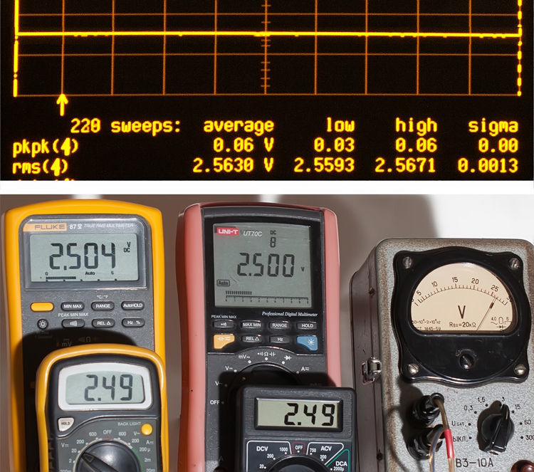
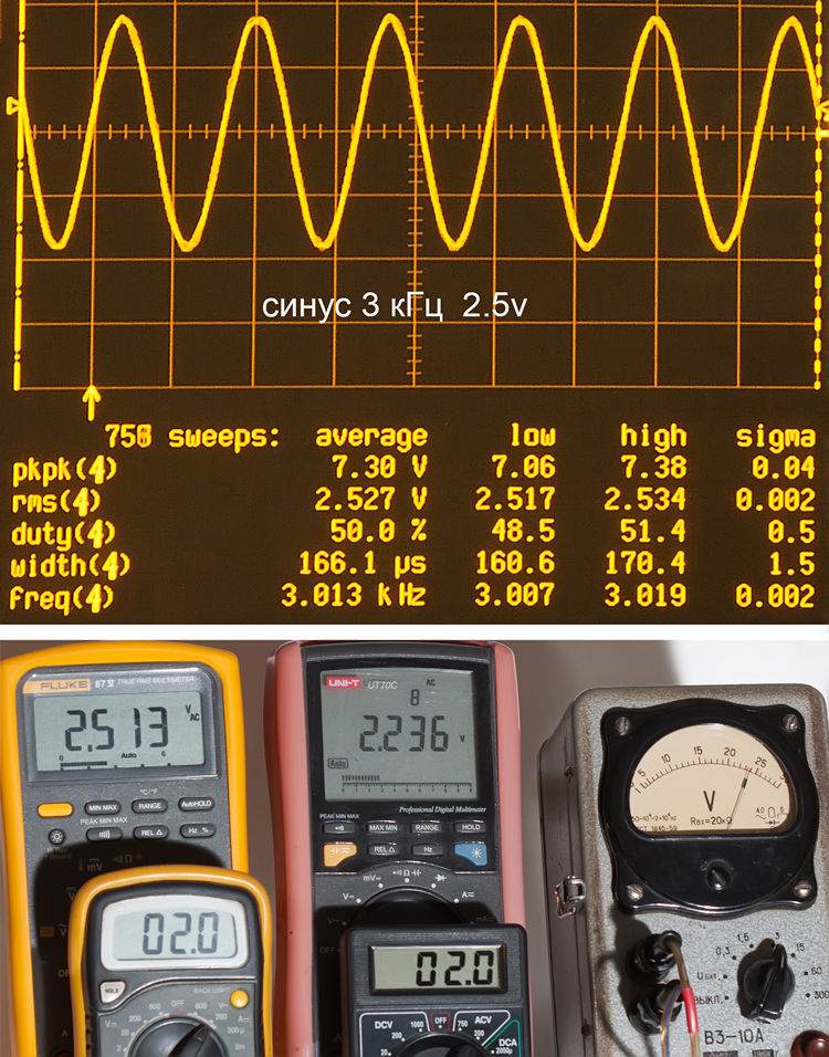
According to this template, all photos are organized in the future: first, the oscillogram, under it the readings of the instruments.
Now making sure that the devices are working, we start the tests. Signals are supplied from low-voltage GSS type G3-36A. Of course, he is not a digital camera, but even better is closer to real conditions.
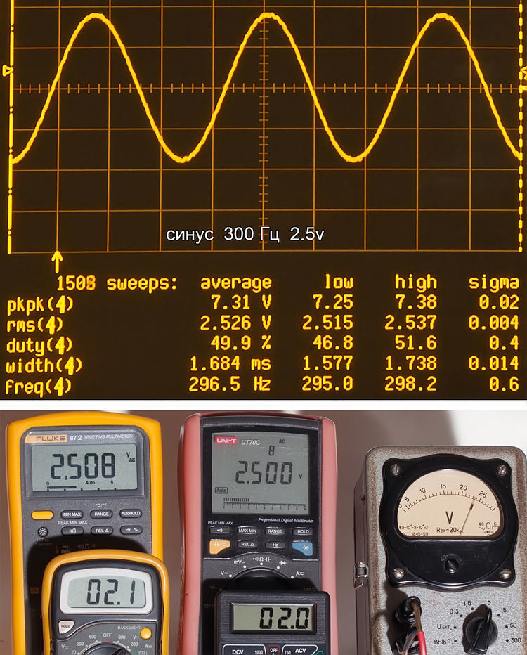
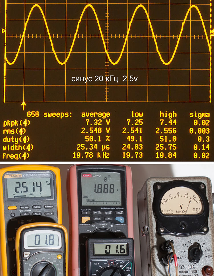
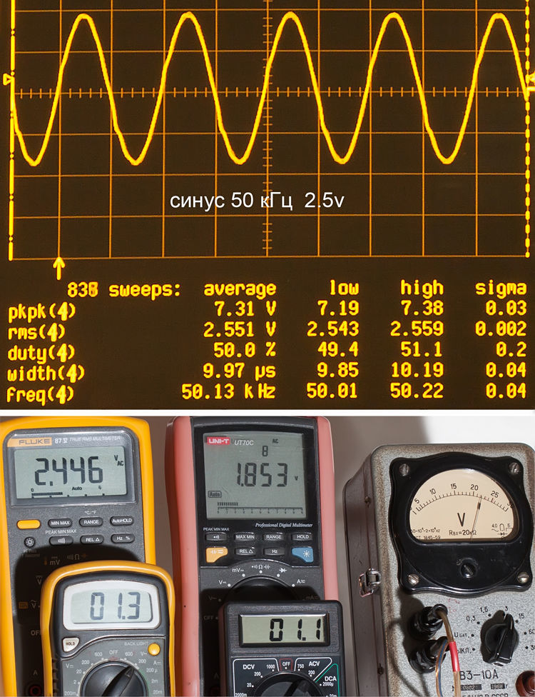
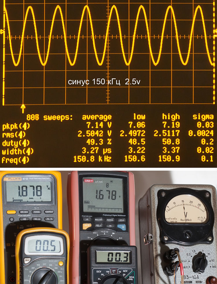
Sinusoidal alternating current of various frequencies We
supply 2.5 v at frequencies of 30 Hz, 300 Hz, 3 kHz, 20 kHz, 50 kHz, and 150 kHz.
Details under the cut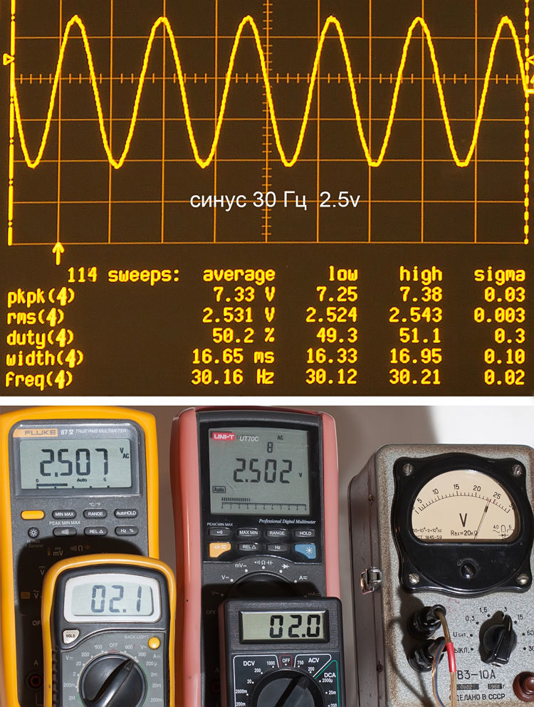
------------------------------------------------------------------------------
------------------------------------------------------------------------------
------------------------------------------------------------------------------
------------------------------------------------------------------------------
------------------------------------------------------------------------------
------------------------------------------------------------------------------
------------------------------------------------------------------------------
------------------------------------------------------------------------------
------------------------------------------------------------------------------
------------------------------------------------------------------------------
The first, strangely enough, began to merge UT70C starting from 3 kHz. At the same time, inexpensive multimeters slipped this barrier - unless of course they did not assume that from the very beginning their error was as much as 16% downward. At 20 kHz, their readings cannot even be called evaluative, so only Fluke and the switch are adequate. That passed 50 kHz is still about the case, but it is already meaningless to measure higher frequencies.
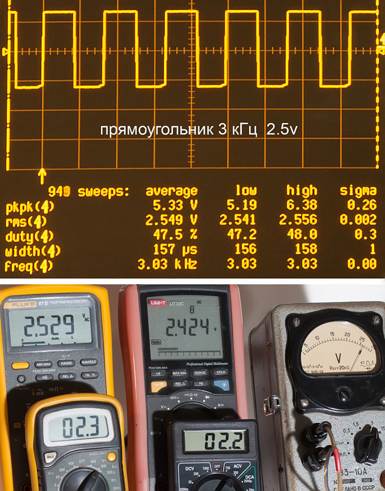
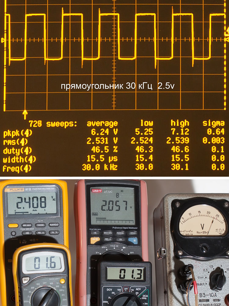
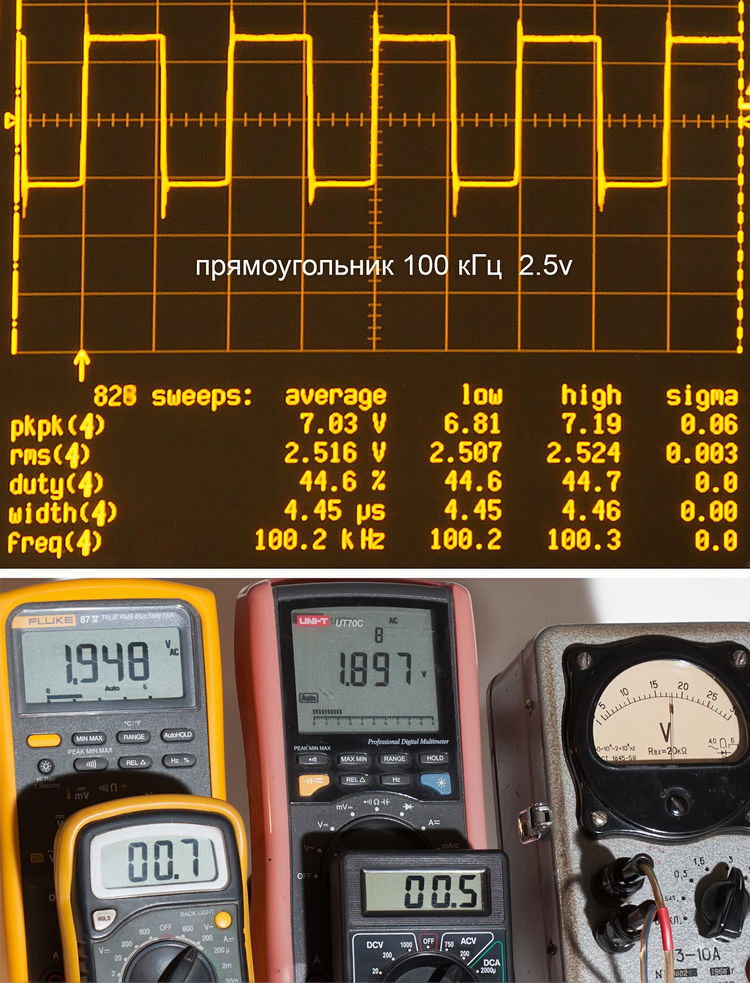
Rectangular test current
This mode, like all further ones, is non-standard for non-“true rms” devices, but we will still conduct research. We supply approximately 2.5 v of rectangular voltage at 30 Hz, 3 kHz, 30 kHz, and 100 kHz.
Details under the cut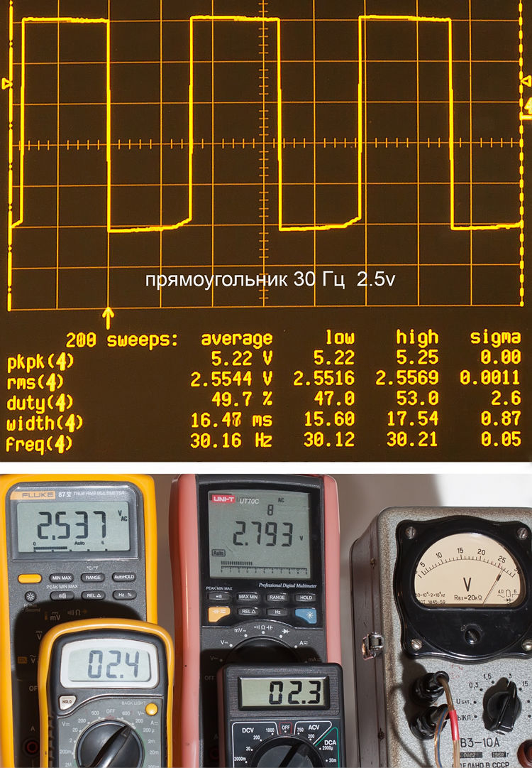
------------------------------------------------------------------------------
------------------------------------------------------------------------------
------------------------------------------------------------------------------
------------------------------------------------------------------------------
------------------------------------------------------------------------------
------------------------------------------------------------------------------
The readings of cheap multimeters have become more adequate at frequencies up to 3 kHz. But the UT70C at Hertz was a bit overstated, but leveled closer to the point at 3 kHz. Higher frequencies pulled only Fluk and arrow.
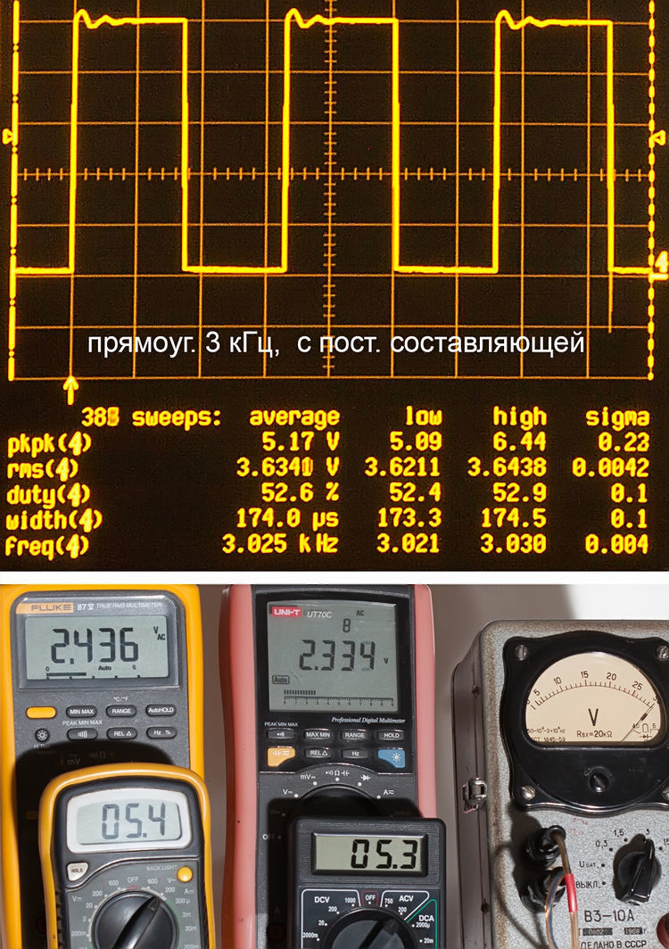
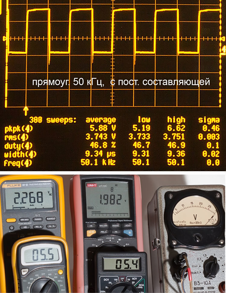
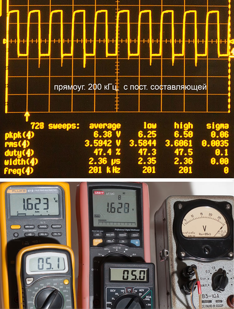
A rectangular signal with a constant component
Let's see how instruments behave at them at frequencies of 300 Hz, 3 kHz, 50 kHz, and 200 kHz.
Details under the cut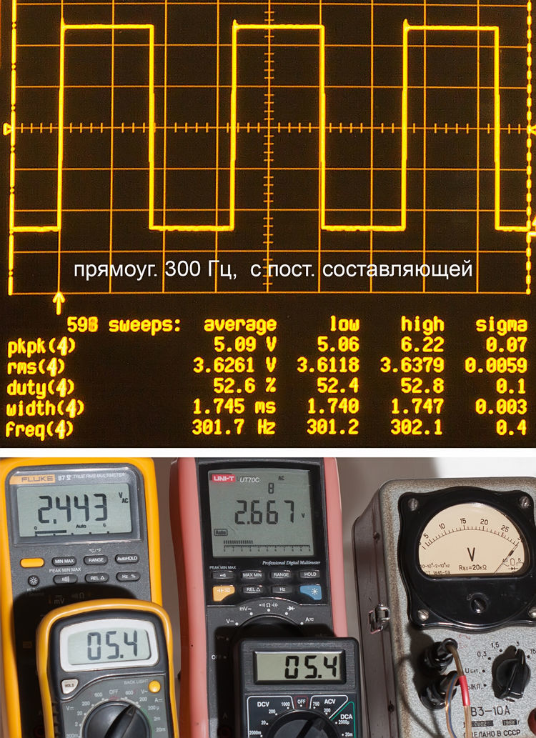
------------------------------------------------------------------------------
------------------------------------------------------------------------------
------------------------------------------------------------------------------
------------------------------------------------------------------------------
------------------------------------------------------------------------------
------------------------------------------------------------------------------
Inexpensive multimeters have shown themselves very effectively, for them the frequency barrier seems to have lost relevance. While normal devices to the last try to work the
send signals of complex shape,
which are obtained by distorting the rectangular voltage by coils and capacitors.
Details under the cut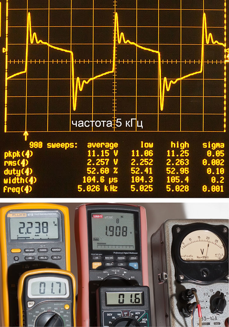
------------------------------------------------------------------------------
------------------------------------------------------------------------------
------------------------------------------------------------------------------
------------------------------------------------------------------------------
------------------------------------------------------------------------------
------------------------------------------------------------------------------
On the first signal with the main frequency of 5 kHz - adequate readings only for Fluk and the needle instrument.
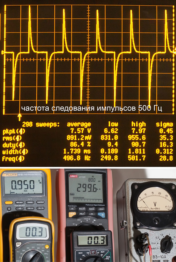
Short bipolar pulses normally digest Flück (and of course the oscilloscope too). But cheap devices practically do not see them. UT-70C gives an error of more than half the current value, and the arrow is also considerable.
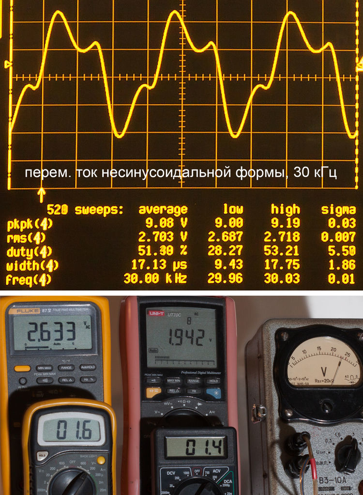
The third experiment at a frequency of 30 kHz is a better result than the previous one, but the error is nonetheless noticeable.
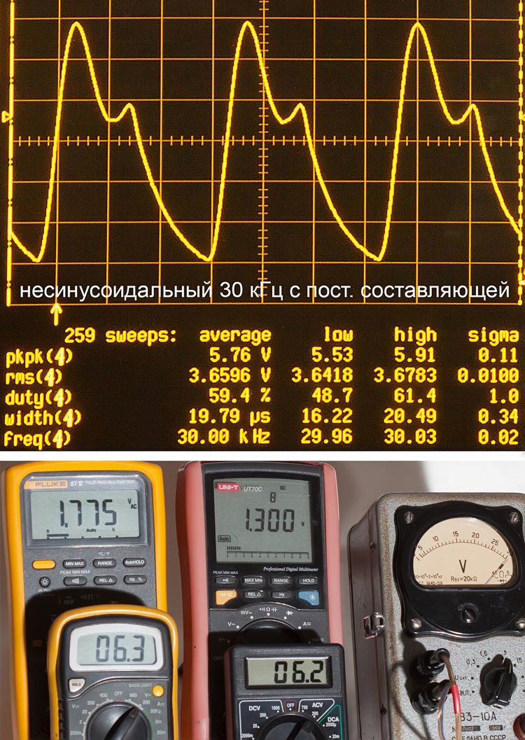
In the fourth experiment, a constant current was applied again. Cheap multimeters and this time gave an amplitude value, so even with some excess.
Upon completion of any research, it is necessary to draw a conclusion.
In this case, it can be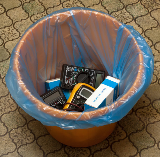
Updated: I will add two comments from readers,
clarifying the paradox of this article
Всем критикующим «измеряли не тем, не так и не то»: статья, ИМХО, является продолжением цикла про строителей сверхъединичных генераторов и как раз и призвана показать, что все эти гении от физики и электротехники, пользуясь дешевыми мультиметрами, измеряют сферического коня в вакууме, а не реальную картину в своих генераторах.
Это не сравнительный обзор тестеров, это обзор тестеров применительно именно к вечнякам, когда подобными тестерами пытаются измерять что-то на мегагерцовых частотах (или постоянку со сложными высокочастотными выбросами).

Да, но это ясно только тем кто читал эти предыдущие статьи. Даже не столько сами статьи, сколько комментарии к ним.
Для тех кто не читал и открывает эту статью это выглядит именно как простой сравнительный тест мультиметров, и как вывод что «вот этим китайским г… пользоваться вообще нельзя», покупайте все Флюки а всему остальному место в мусорном ведре. Хотя вывод как раз из всех проведенных тестов можно совсем другой(противоположный) сделать — для своей области применения дешевые китайские тестеры даже на удивление адекватны — дают ровно то что заявлено производителями и сколько заплачено (с учетом цены даже пожалуй больше чем можно ожидать за такую цену)…
Всем критикующим «измеряли не тем, не так и не то»: статья, ИМХО, является продолжением цикла про строителей сверхъединичных генераторов и как раз и призвана показать, что все эти гении от физики и электротехники, пользуясь дешевыми мультиметрами, измеряют сферического коня в вакууме, а не реальную картину в своих генераторах.
Это не сравнительный обзор тестеров, это обзор тестеров применительно именно к вечнякам, когда подобными тестерами пытаются измерять что-то на мегагерцовых частотах (или постоянку со сложными высокочастотными выбросами).
Да, но это ясно только тем кто читал эти предыдущие статьи. Даже не столько сами статьи, сколько комментарии к ним.
Для тех кто не читал и открывает эту статью это выглядит именно как простой сравнительный тест мультиметров, и как вывод что «вот этим китайским г… пользоваться вообще нельзя», покупайте все Флюки а всему остальному место в мусорном ведре. Хотя вывод как раз из всех проведенных тестов можно совсем другой(противоположный) сделать — для своей области применения дешевые китайские тестеры даже на удивление адекватны — дают ровно то что заявлено производителями и сколько заплачено (с учетом цены даже пожалуй больше чем можно ожидать за такую цену)…
Only registered users can participate in the survey. Sign in , please.