The smart REDMOND Smart plug SkyPlug RSP-100S (Part 2). The main drawback of the outlet and its elimination
So, finally, I “finished off” the second part of the Redmond SkyPlug RSP-100S Smart Socket.
As I told in the first part - the article “Smart Redmond SkyPlug RSP-100S socket. Analysis of the design and circuit of electrical principle. Identifying flaws, ” I had to draw a diagram of this outlet in order to finalize it. I didn’t really like another one, in my opinion, the main drawback of this smart outlet, which I didn’t talk about in the first part. In general, I like to modify something, my colleagues at work even joke that if something is not finished by me, then this is something that is not mine. :)
So, we will announce this disadvantage, and this, if many have not guessed, looking at the scheme, is the absence of an autonomous power source. The fact is that the nRF51822 IC has a real-time clock, and they work, i.e. time is counted only when there is power from the network, because There is no internal power source, neither a battery, nor a battery, nor even an ionistor. This means that if a power outage occurs, even for a short time, the clock will be reset and previously stored on / off programs will become irrelevant. Using a smart outlet, I almost immediately drew attention to this shortcoming, and gave it great importance, because electricity in my city is cut off often. Especially often there are shutdowns during a thunder-storm, etc. And another disadvantage is that the socket does not save the current state,
I once had to leave home for a couple of weeks, and I asked one wonderful person to come to my house to feed aquarium fish. And one day, she calls me and says that the lighting does not burn in the aquarium. I asked to see if the clock on the microwave oven showed time, to which I received the answer — no, and this is my power outage indicator. I immediately realized that there was a power outage, and when the power supply was restored, the smart socket did not turn on, because it did not provide for the storage of the latter state in the firmware. But even if the state was kept, then due to the lack of exact time, this state could be irrelevant, for example, if the electricity was turned off during the day and restored in the deep night, when lighting in the same aquarium is no longer required. Here the idea arose to modify the smart socket and introduce some kind of self-contained power source into it. To do this, I needed to find out the principle of operation and, as a result, to know the electrical concept of the smart socket: what are the supply voltages, what components, what Bluetooth controller, where are the on / off programs stored and where the time and days of the week go, and dates. The countdown of all logic in the outlet should have been built in, since the on / off programs via the smartphone are set by the day of the week and for a certain time, and the Bluetooth connection with the smartphone is not always supported and, therefore, the smart socket has no constant time and program synchronization. As a result of the work done, described in the first part, I determined that the on / off programs are stored in the memory of the Bluetooth controller itself and it also has a real-time clock, and the clock is synchronized when the smart socket is connected via Bluetooth to a smartphone, i.e. time is taken from the smartphone at each connection.
As a result, it became clear that protection against loss of electricity in the electric lighting network, at least for a couple of hours, is necessary, and this can be solved only by introducing the above described devices: battery, battery or ionistor.
1 SEARCH FOR AUTONOMOUS POWER SUPPLY
To begin, I decided to try the simplest - the ionistor, because this device does not need to enter any charging schemes, and it is enough to connect it in parallel to the power supply terminals of the Bluetooth controller, and the ionistor would be charged from the power source to the voltage of this source. I soldered to pins 1 and 4 of the footprint for the XP1 plug (I remind you that this plug is not on the board, but there is space for it and holes, the extreme terminals of which 1 and 4 are pins connected to the power supply of the Bluetooth controller, and there must be present voltage 3.3 V). The ionistor was charged to the power supply voltage of the Bluetooth controller, but after disconnecting the smart outlet from the mains, the ionistor was discharged in about a minute. The accumulated energy of the ionistor was not enough to maintain power for a couple of hours, because There are cases of power outages for 1 - 2 hours. I must say that I put the ionistor not very large capacity, only 0.33 F, because the larger capacitance of the ionistors was already fairly decent in size and it would not be easy to insert them into the outlet. And, as practice has shown, even if you put the ionistor at 1.0 F, it would also not be enough for as long as we would like, but, of course, it would be quite suitable for short-term power outages.
After the ionistor, there was a thought to put something like a lithium battery, the type as on computers - CR2032, but not that size, but smaller - CR1620. But, this idea almost immediately dropped out, because the battery is short-lived - it will quickly set down and cannot be charged, and it is also difficult to connect it - soldering the conductors to it is not a good idea, because You can overheat and it will fail. I did not find small-sized batteries with welded leads in my city, but even if I did, I had to disassemble the socket each time, or put them outside, which would increase the size of the smart socket and the aesthetic appearance would be lost.
When I was looking for ionistors and batteries, I noticed small Li-Pol batteries in one of the radio shops in the storefront, in the form of a rectangular parallelepiped and, importantly, suitable, in my opinion, dimensions. The store had batteries with a capacity of 20, 40, 65 and 100 mAh. I then figured that it seemed to be the most suitable for 65 mA • h in overall dimensions, but I still had to look inside the outlet and evaluate the space under the battery so as not to be disappointed by buying the wrong one, and the price is rather big: from 200 up to 350 rubles and, as for evil, 65 mA • h - the most expensive.
2 PROCESSING OF AUTONOMOUS POWER SUPPLY ON THE BASIS OF THE BATTERY
Since it was decided to put the battery, now there was a problem in applying the charging circuit of this battery and organizing the power supply from it to the Bluetooth controller chip, since the operating voltage on it is 3.6 V, according to the datasheet, and a fully charged Li-Pol battery produces a voltage of 4.2 V. A small current is required to charge the battery, especially with such a small capacity, and it was necessary to make a charge circuit with current limitation . Immediately came to mind the scheme on the IC TP4056. Ready-made handkerchiefs - chargers for Li-Ion batteries, based on this chip, I ordered a well-known site not so long ago, and when they arrived, they were not immediately used, and they were safely sent to the box, where they waited for their fate. They did not have to wait long for at least one of them. The board looks like the photo below, there is an IC TP4056, mode indication LEDs and the rest of the strapping. Although this chip is for Li-Ion batteries, but I think it will do for Li-Pol too.

Figure 1 - Battery charge controller based on IC TP4056
According to the description on the seller’s website, this instance is designed for a charging current of 1 A, this is explained by the applied resistor nominal value installed between the common wire (IN-) and output 2 of the chip, in the photo this resistor is below - 1.2 kOhm, which is according to the datasheet According to the datasheet, in which a table of charge currents was given depending on the resistor rating, I could not find a resistor that would give a charge current of less than 130 mA, which is twice the battery capacity, and the batteries are usually charged with a current not more than 0.2 from C (where C is the capacity of the battery). In this case, I assumed that the battery with a capacity of 65 mA • h is suitable for me, i.e. C = 65 mA • h, from where we determine the charge current 13 mA. To provide such a current limit, it was necessary to choose a resistor between the common wire and the output 2 of the chip. According to the existing resistor ratings and the corresponding currents, I made a graph, on which I conditionally continued the line in the direction of increasing the resistor resistance and approximately determined the required rating at the required current, I chose a resistance of 62 kΩ. Then, according to the datasheet, the resistor going from the power source to the IC 4040 power output (pin 4) should be from 0.2 to 0.5 ohms, but since the board was a 0 ohm resistor (jumper), I decided to follow the datasheet and from the available small surface resistors, I found one for 1 Ohm and two for 1.5 Ohm, soldered them all in parallel and thereby gained resistance of about 0.43 Ohm. Honestly, I don’t know why, this resistor, judging by the circuit, this resistor is not a shunt, but perhaps it is in case of a short circuit in the battery to limit the current. on which I conditionally continued the line in the direction of increasing the resistance of the resistor and approximately determined the required nominal value at the required current, I chose the resistance of 62 kΩ. Then, according to the datasheet, the resistor going from the power source to the IC 4040 power output (pin 4) should be from 0.2 to 0.5 ohms, but since the board was a 0 ohm resistor (jumper), I decided to follow the datasheet and from the available small surface resistors, I found one for 1 Ohm and two for 1.5 Ohm, soldered them all in parallel and thereby gained resistance of about 0.43 Ohm. Honestly, I don’t know why, this resistor, judging by the circuit, this resistor is not a shunt, but perhaps it is in case of a short circuit in the battery to limit the current. on which I conditionally continued the line in the direction of increasing the resistance of the resistor and approximately determined the required nominal value at the required current, I chose the resistance of 62 kΩ. Then, according to the datasheet, the resistor going from the power source to the IC 4040 power output (pin 4) should be from 0.2 to 0.5 ohms, but since the board was a 0 ohm resistor (jumper), I decided to follow the datasheet and from the available small surface resistors, I found one for 1 Ohm and two for 1.5 Ohm, soldered them all in parallel and thereby gained resistance of about 0.43 Ohm. Honestly, I don’t know why, this resistor, judging by the circuit, this resistor is not a shunt, but perhaps it is in case of a short circuit in the battery to limit the current. According to the datasheet, the resistor going from the power supply to the IC 4040 power output (pin 4) should be from 0.2 to 0.5 ohms, but since the board was equipped with a 0 ohm resistor (jumper), I decided to follow the datasheet and existing small surface resistors found one for 1 ohm and two for 1.5 ohm, soldered them all in parallel and thereby gained a resistance of about 0.43 ohms. Honestly, I don’t know why, this resistor, judging by the circuit, this resistor is not a shunt, but perhaps it is in case of a short circuit in the battery to limit the current. According to the datasheet, the resistor going from the power supply to the IC 4040 power output (pin 4) should be from 0.2 to 0.5 ohms, but since the board was equipped with a 0 ohm resistor (jumper), I decided to follow the datasheet and existing small surface resistors found one for 1 ohm and two for 1.5 ohm, soldered them all in parallel and thereby gained a resistance of about 0.43 ohms. Honestly, I don’t know why, this resistor, judging by the circuit, this resistor is not a shunt, but perhaps it is in case of a short circuit in the battery to limit the current. I soldered them all in parallel and thereby gained a resistance of about 0.43 ohms. Honestly, I don’t know why, this resistor, judging by the circuit, this resistor is not a shunt, but perhaps it is in case of a short circuit in the battery to limit the current. I soldered them all in parallel and thereby gained a resistance of about 0.43 ohms. Honestly, I don’t know why, this resistor, judging by the circuit, this resistor is not a shunt, but perhaps it is in case of a short circuit in the battery to limit the current.
Now that the resistors were picked up and soldered, it was necessary to cut off the excess charge from the charge controller card, namely the area where the mini-USB connector was soldered, this area would not allow the board to be inserted into the place provided for it in the case, and if it was cut off, then The board is clearly placed where I determined it. So, dismantle the mini-USB socket, so that it is more convenient to cut off the excess with metal scissors. Below in the picture you can see what the board looks like after the revision.

Figure 2 - Modified battery charge controller
And here you can see where you can place the charge controller board in the smart socket box:

Figure 3 - Placement of the battery charge controller in the smart socket box
Then, the following problem occurred. Now you need to power the charge controller with something, because the transformerless power source of the smart socket was designed for 12 V, in the mode when the relay is off, and the TP4056 charge controller, according to the datasheet, is powered by no more than 8 V. , and it was necessary to lower the voltage to ensure proper operation of the TP4056. But it is best to feed on 5 V, because This is a more common voltage, and besides, there was a mini-USB socket on the board, which meant power supply from 5 V. The simplest and small-sized one I could think of to get 5 V was to install a linear stabilizer in the SOT-23 or SOT-89 package, because load currents (charging) will not exceed 100 mA, which is usually designed for such small-sized stabilizers. From the existing arsenal, there was a L78L05ABUTR microcircuit in the SOT-89 package, which I decided to use, but it had to be put somewhere and mounted on a small piece to solder - you could break the conclusions, and there was a risk to close something Because there is not so much free space on the smart socket board. Therefore, quickly made a handkerchief for this chip, which also provided for the installation of ceramic capacitors.

Figure 4 - Linear voltage regulator at 5 V
Now that there was a charge controller and power supply board for the charge controller, I was able to estimate the place of their installation, and now I could see where one of the attracted batteries would stand. I visited that store again, looked at everything again, and still chose the one that was 65 mAh, you can see it in the picture below.

Figure 5 - Li-Pol battery LP451124
3 ASSEMBLY OF AUTONOMOUS POWER SYSTEM
Now there is a battery, charge circuit, voltage regulator for the charge circuit, connect it all in the appropriate sequence and get the design as in the picture below.

Figure 6 - Battery with charge controller
We check this assembly in work. We supply a voltage of slightly more than 5 V to the stabilizer and look at the voltage at the output of the stabilizer and then on the battery. In my case, everything worked right away, a charge current came to the battery, and a red LED was on. Having a little endured and controlling the charge current, I concluded that the loading was slow, that it would be necessary to increase the charge current. I looked again at the datasheet on the battery and it was said that the standard charge current of this battery was 0.5 • C, which corresponds to a current of 27.5 mA. Then I reduced the resistance of the resistor, which sets the charge current to 47 kΩ, with the result that the battery is charged faster and the green LED on the controller lights up, indicating the end of charge.
There is a battery, charge controller and voltage regulator for the charge controller, now we need to consider the power supply of the nRF51822 Bluetooth controller, so as not to exceed the 3.6 V supply voltage, and even better not exceed 3.0 - 3.3 V, at which the manufacturer guarantees normal operation. To do this, the simplest and most compact one can think of is to apply voltage from the battery through two series-connected diodes of type 1N4148, on which 0.5-0.6 V falls on each, eventually we get a voltage of 3.0-3 after the diodes , 2 V, which is permissible for the operation of the IC nRF51822. Also, the diodes will not allow the battery to discharge when the voltage is present in the network, the output of the linear stabilizer DD1 in the composition of the native smart socket circuit will have a voltage of 3.3 V, as a result, the diodes will close and the voltage will not flow to the battery and also the voltage from the battery will not flow to nRF51822 during the presence of voltage in the network. Even in the datasheet on nRF51822 it is said that the minimum operating voltage is 1.8 V, which, when the battery is discharged to 2.8 - 3 V, will allow us to support the operation of the nRF51822 in the absence of electricity in the network, which means that the real-time clock will not reset to this time will be maintained in the "On" or "Off" state - as before the power outage, and this state will be maintained until the program is triggered, if the time comes, if it has been set, or until the battery is dead.
4 CIRCUIT ELECTRIC PRINCIPAL CLEVER SOCKETS WITH AUTONOMOUS POWER
We build a new basic electrical circuitry of a modified smart socket, an independent power source based on a Li-Pol battery. The scheme is shown in the figure below.

Figure 7 - Circuit
diagram of the final smart socket design On the diagram, the additional diodes of type 1N4148 have reference numerals D1 and D2, for convenience of searching, are also outlined with a dashed line within the A1 board.
5 INSTALLATION OF AUTONOMOUS POWER SUPPLY SYSTEM ON THE BASIS OF THE BATTERY. ASSEMBLY OF A NEW CONSTRUCTION OF A SMART SOCKET
According to the scheme, additional diodes should be installed on the smart socket board, then install the battery, charge controller and stabilizer in the smart socket case to the designated places and unsolder all inputs and outputs.
We put the charge controller and stabilizer as shown in the picture below. The charge controller board is simply inserted into the space between the stand under the screw and the protrusion of the socket under the plug, it is inserted there relatively tightly - it does not hang out and does not pop up, and we put the voltage regulator board for the controller on the hot-melt glue with the elements towards the socket. You can also see that I have half-glued the grounding bracket with heat-resistant tape, for which it will become clear below.
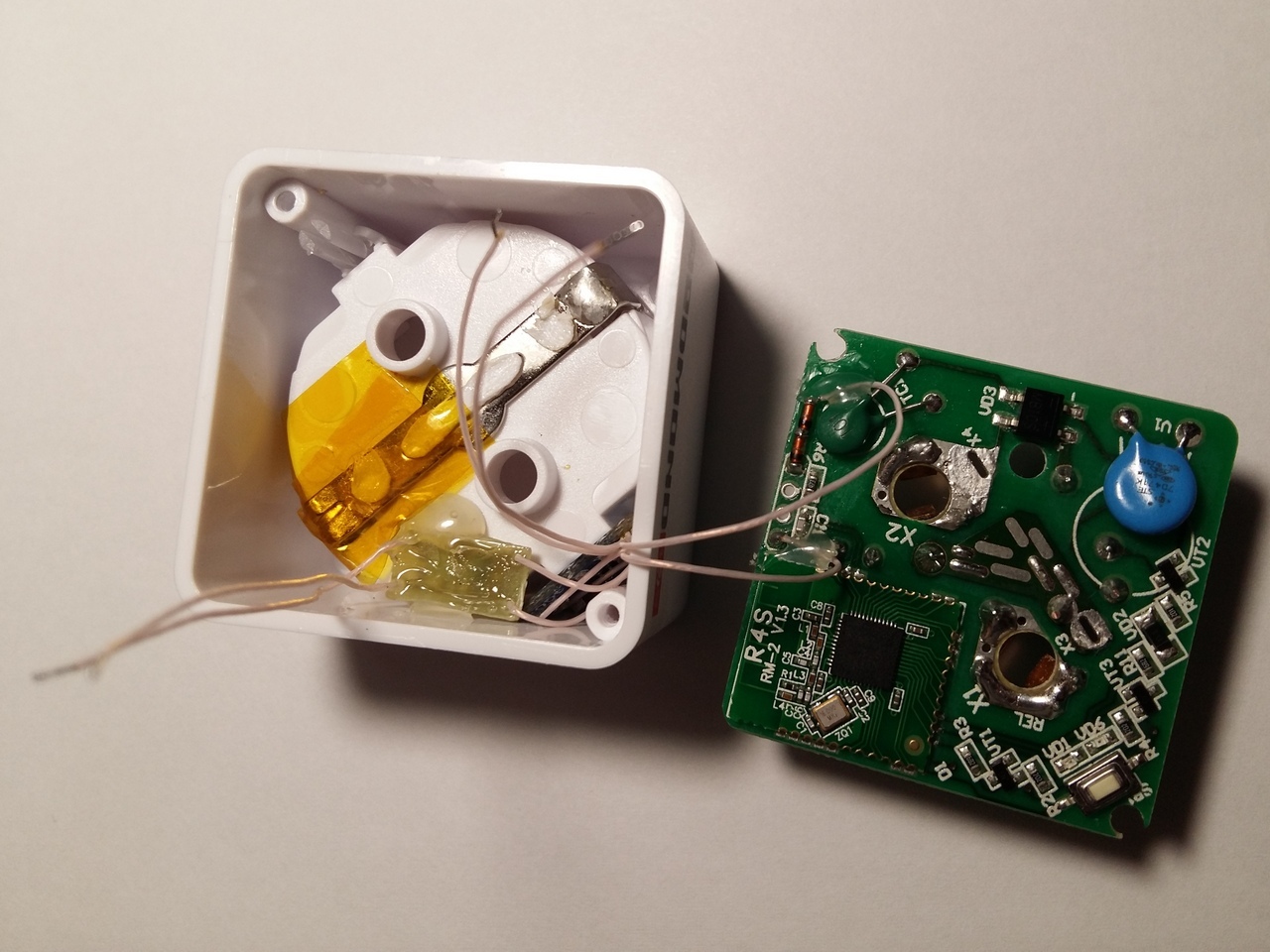
Figure 8 - Installation of the charge controller
Install the battery in place, as shown in the photo below:

Figure 9 - Install the battery
The picture shows that the battery is installed in the opening of one of the corners of the outlet housing on one side of the grounding bracket. To isolate this bracket, I pasted over two layers of heat-resistant tape, first, it isolates the battery leads, and secondly, there will be additional phase and ground insulation, since unbound phase voltage present on battery. Conductors of the corresponding polarity, which run from the charge controller board, are soldered to the battery terminals, and the conductors go from the charge controller board to power the Bluetooth controller through the diodes to the socket board, as shown in the circuit diagram. I insulated the terminals of the battery with soldered conductors with a shrink tube, while bending the terminals and part of the shell gently without sharp movements at 90 ° to the base of the socket where the grounding bracket is installed.
Unsoldering of the power supply circuits of the stabilizer and the battery output, as well as the installation of additional diodes D1 and D2 can be made as shown in the photo below.

Figure 10 - Wiring of battery circuits and additional diodes
Such installation of the battery, charge controller and voltage regulator for the charge controller allows you to easily assemble an outlet, i.e. the battery and additional boards after assembly do not interfere at all with the main board: nothing rests or touches. But still, for reliability, I insulated with heat-resistant tape the place of soldering the ground wire going to the load grounding clip from the network grounding clip. And you should also pay attention to the flexible conductors, which during assembly must be refilled so that they do not cross the contact holes for the power supply plug. Perhaps, as in my case, you need to grab them somewhere with hot melt. By the way, I used the MGTF-0.12 wire as conductors, it is quite strong for high-voltage breakdown and the insulation does not melt when soldering.

Figure 11 - Packaging of conductors around the outlet holes
After mounting the battery, I noticed that the bracket that grounds the load, if you insert the load plug into the smart socket, will be strongly pressed against the battery, which can damage or short-circuit the battery, so this bracket modify, namely bend, as shown in the photo below.

Figure 12 - Molding of the grounding bracket contacts
Of course, it is possible to completely remove this bracket, but it is safer with the ground if you have a three-wire power grid.
6 INSPECTION OF WORK AND CONDUCTING OF PRELIMINARY TESTS OF THE DEVELOPED SMART SOCKET
As a result, after the work done and the assembly, we have a smarter outlet, i.e. less dependent on a power outage, with a battery and a battery charge controller on board, and even through the case you can see the glow of the charge controller LEDs, the red one is charging, the green one is over.

Figure 13 - Charge mode indication
After assembly, a test was carried out, charging was carried out, over time, a green LED illuminated, indicating that the charge was completed, the real-time clock considered “On” / “Off”, respectively, is also supported, but if it were not for one “but”. As it turned out, during the power failure there was an “On” state, that is, the VT2 transistor remained open, after the electricity was restored in the network, the socket turned on in the previous state and you can see that the VD6 “On” LED is on, but since the transistor is open, then the moment of power supply, the current from the diode bridge output immediately goes through the relay coil and transistor, as a result, the capacitor does not have time to charge up to 12 V and the voltage is immediately drawn down to 5 - 6 V, which was not enough to guarantee the relay to operate. Happened,
7 ADDITIONAL INTRODUCTION OF CHANGES IN THE POWER SUPPLY OF A SMART SOCKET. FINAL TESTS
I began to find out what kind of ballast capacitors C3 and C5 were used in this outlet, so that, if possible, find the same ones and add them. Measured their capacity, received about 0.47 microfarad each, for a total of about 1 microfarad. But it is not possible to measure the voltage, but judging by the size of the capacitors and the mains voltage, it should have been approximately 400 to 500 V. In the typical sizes of these capacitors there is a voltage of 500 V for such capacitances, but according to the information found on the Murata website similar capacitorsAt voltages of about 220 V, the capacitance of these capacitors is significantly lower than their nominal value at low voltages. From here it became clear why these capacitors do not provide sufficient power so that there is no significant voltage drop at the output of this power source. And then there was added a battery charge circuit, which also took some current, about 10 - 20 mA, until the battery is charged. Since such capacitors do not perform well at high voltages, I decided to try to find a small-sized metal-foil capacitor, at least 400 V and with a less or less normal capacity. I began to dig in the old boards of various devices and found on one of the boards a small-sized imported metal-foil capacitor of 450 V and a capacity of 0.47 microfarad.

Figure 14 - 450 V metal-film capacitor - 0.47 microfarad.
Vypayal this capacitor, examined the board smart socket, and it turned out that for him there is a very suitable place.

Figure 15 - Checking the possibility of placing an additional capacitor The
capacitor came up in height and thickness across that place as in the picture above, and it was decided to use it - solder parallel to the ballast capacitors C3 and C5, and it can be fixed with hot melt adhesive.
I soldered the MGTF-0.2 wires to the terminals of the capacitor, insulated the pestle with the rations of wires with a heat shrink tube and additionally with hot melt adhesive. Then the capacitor stuck to the relay with hot melt and soldered the conductors parallel to the capacitor C3.

Figure 16 - Installation of additional ballast condenser
After installing this capacitor, I immediately checked the operability of the smart socket in this way, namely, in the “On” state, inserted this outlet into the network, as a result of which the relay worked, the contacts closed, the voltage on the C4 capacitor was set at about 9 V, which was enough to start the relay and to work the other bodies of the outlet. Of course, with such a voltage, the current consumption of the coil is higher and, therefore, the power consumption of the socket increased, I measured it with a digital wattmeter, the idling power was 2.2 watts. You can try to optimize and try to further reduce the voltage to a level at which the relay will operate reliably and the current consumption will be minimal, but at this stage I did not bother, the main thing is that now the outlet with autonomous power, therefore, the clock will not stray when the mains voltage drops, until the battery sits down and the state is “On” or “Off”. Also, an experiment was conducted on battery life, which was 10 - 11 hours, which is quite enough, because Electricity for such or more time is rarely turned off.
8 TOTAL schematic circuit diagram SMART OUTLET self-powered
And after all the modifications, the final circuit smart outlet is as follows:

Figure 17 - schematic circuit diagram smart sockets with battery
In this scheme, the additional ballast capacitor, the parallel capacitors C3 and C5, designated as Cb and dashed.
That's all, the second outlet, perhaps, somehow I will finish the same way. Criticism and possibly additional recommendations are welcome.
Thanks for attention!
As I told in the first part - the article “Smart Redmond SkyPlug RSP-100S socket. Analysis of the design and circuit of electrical principle. Identifying flaws, ” I had to draw a diagram of this outlet in order to finalize it. I didn’t really like another one, in my opinion, the main drawback of this smart outlet, which I didn’t talk about in the first part. In general, I like to modify something, my colleagues at work even joke that if something is not finished by me, then this is something that is not mine. :)
So, we will announce this disadvantage, and this, if many have not guessed, looking at the scheme, is the absence of an autonomous power source. The fact is that the nRF51822 IC has a real-time clock, and they work, i.e. time is counted only when there is power from the network, because There is no internal power source, neither a battery, nor a battery, nor even an ionistor. This means that if a power outage occurs, even for a short time, the clock will be reset and previously stored on / off programs will become irrelevant. Using a smart outlet, I almost immediately drew attention to this shortcoming, and gave it great importance, because electricity in my city is cut off often. Especially often there are shutdowns during a thunder-storm, etc. And another disadvantage is that the socket does not save the current state,
I once had to leave home for a couple of weeks, and I asked one wonderful person to come to my house to feed aquarium fish. And one day, she calls me and says that the lighting does not burn in the aquarium. I asked to see if the clock on the microwave oven showed time, to which I received the answer — no, and this is my power outage indicator. I immediately realized that there was a power outage, and when the power supply was restored, the smart socket did not turn on, because it did not provide for the storage of the latter state in the firmware. But even if the state was kept, then due to the lack of exact time, this state could be irrelevant, for example, if the electricity was turned off during the day and restored in the deep night, when lighting in the same aquarium is no longer required. Here the idea arose to modify the smart socket and introduce some kind of self-contained power source into it. To do this, I needed to find out the principle of operation and, as a result, to know the electrical concept of the smart socket: what are the supply voltages, what components, what Bluetooth controller, where are the on / off programs stored and where the time and days of the week go, and dates. The countdown of all logic in the outlet should have been built in, since the on / off programs via the smartphone are set by the day of the week and for a certain time, and the Bluetooth connection with the smartphone is not always supported and, therefore, the smart socket has no constant time and program synchronization. As a result of the work done, described in the first part, I determined that the on / off programs are stored in the memory of the Bluetooth controller itself and it also has a real-time clock, and the clock is synchronized when the smart socket is connected via Bluetooth to a smartphone, i.e. time is taken from the smartphone at each connection.
As a result, it became clear that protection against loss of electricity in the electric lighting network, at least for a couple of hours, is necessary, and this can be solved only by introducing the above described devices: battery, battery or ionistor.
1 SEARCH FOR AUTONOMOUS POWER SUPPLY
To begin, I decided to try the simplest - the ionistor, because this device does not need to enter any charging schemes, and it is enough to connect it in parallel to the power supply terminals of the Bluetooth controller, and the ionistor would be charged from the power source to the voltage of this source. I soldered to pins 1 and 4 of the footprint for the XP1 plug (I remind you that this plug is not on the board, but there is space for it and holes, the extreme terminals of which 1 and 4 are pins connected to the power supply of the Bluetooth controller, and there must be present voltage 3.3 V). The ionistor was charged to the power supply voltage of the Bluetooth controller, but after disconnecting the smart outlet from the mains, the ionistor was discharged in about a minute. The accumulated energy of the ionistor was not enough to maintain power for a couple of hours, because There are cases of power outages for 1 - 2 hours. I must say that I put the ionistor not very large capacity, only 0.33 F, because the larger capacitance of the ionistors was already fairly decent in size and it would not be easy to insert them into the outlet. And, as practice has shown, even if you put the ionistor at 1.0 F, it would also not be enough for as long as we would like, but, of course, it would be quite suitable for short-term power outages.
After the ionistor, there was a thought to put something like a lithium battery, the type as on computers - CR2032, but not that size, but smaller - CR1620. But, this idea almost immediately dropped out, because the battery is short-lived - it will quickly set down and cannot be charged, and it is also difficult to connect it - soldering the conductors to it is not a good idea, because You can overheat and it will fail. I did not find small-sized batteries with welded leads in my city, but even if I did, I had to disassemble the socket each time, or put them outside, which would increase the size of the smart socket and the aesthetic appearance would be lost.
When I was looking for ionistors and batteries, I noticed small Li-Pol batteries in one of the radio shops in the storefront, in the form of a rectangular parallelepiped and, importantly, suitable, in my opinion, dimensions. The store had batteries with a capacity of 20, 40, 65 and 100 mAh. I then figured that it seemed to be the most suitable for 65 mA • h in overall dimensions, but I still had to look inside the outlet and evaluate the space under the battery so as not to be disappointed by buying the wrong one, and the price is rather big: from 200 up to 350 rubles and, as for evil, 65 mA • h - the most expensive.
2 PROCESSING OF AUTONOMOUS POWER SUPPLY ON THE BASIS OF THE BATTERY
Since it was decided to put the battery, now there was a problem in applying the charging circuit of this battery and organizing the power supply from it to the Bluetooth controller chip, since the operating voltage on it is 3.6 V, according to the datasheet, and a fully charged Li-Pol battery produces a voltage of 4.2 V. A small current is required to charge the battery, especially with such a small capacity, and it was necessary to make a charge circuit with current limitation . Immediately came to mind the scheme on the IC TP4056. Ready-made handkerchiefs - chargers for Li-Ion batteries, based on this chip, I ordered a well-known site not so long ago, and when they arrived, they were not immediately used, and they were safely sent to the box, where they waited for their fate. They did not have to wait long for at least one of them. The board looks like the photo below, there is an IC TP4056, mode indication LEDs and the rest of the strapping. Although this chip is for Li-Ion batteries, but I think it will do for Li-Pol too.
Figure 1 - Battery charge controller based on IC TP4056
According to the description on the seller’s website, this instance is designed for a charging current of 1 A, this is explained by the applied resistor nominal value installed between the common wire (IN-) and output 2 of the chip, in the photo this resistor is below - 1.2 kOhm, which is according to the datasheet According to the datasheet, in which a table of charge currents was given depending on the resistor rating, I could not find a resistor that would give a charge current of less than 130 mA, which is twice the battery capacity, and the batteries are usually charged with a current not more than 0.2 from C (where C is the capacity of the battery). In this case, I assumed that the battery with a capacity of 65 mA • h is suitable for me, i.e. C = 65 mA • h, from where we determine the charge current 13 mA. To provide such a current limit, it was necessary to choose a resistor between the common wire and the output 2 of the chip. According to the existing resistor ratings and the corresponding currents, I made a graph, on which I conditionally continued the line in the direction of increasing the resistor resistance and approximately determined the required rating at the required current, I chose a resistance of 62 kΩ. Then, according to the datasheet, the resistor going from the power source to the IC 4040 power output (pin 4) should be from 0.2 to 0.5 ohms, but since the board was a 0 ohm resistor (jumper), I decided to follow the datasheet and from the available small surface resistors, I found one for 1 Ohm and two for 1.5 Ohm, soldered them all in parallel and thereby gained resistance of about 0.43 Ohm. Honestly, I don’t know why, this resistor, judging by the circuit, this resistor is not a shunt, but perhaps it is in case of a short circuit in the battery to limit the current. on which I conditionally continued the line in the direction of increasing the resistance of the resistor and approximately determined the required nominal value at the required current, I chose the resistance of 62 kΩ. Then, according to the datasheet, the resistor going from the power source to the IC 4040 power output (pin 4) should be from 0.2 to 0.5 ohms, but since the board was a 0 ohm resistor (jumper), I decided to follow the datasheet and from the available small surface resistors, I found one for 1 Ohm and two for 1.5 Ohm, soldered them all in parallel and thereby gained resistance of about 0.43 Ohm. Honestly, I don’t know why, this resistor, judging by the circuit, this resistor is not a shunt, but perhaps it is in case of a short circuit in the battery to limit the current. on which I conditionally continued the line in the direction of increasing the resistance of the resistor and approximately determined the required nominal value at the required current, I chose the resistance of 62 kΩ. Then, according to the datasheet, the resistor going from the power source to the IC 4040 power output (pin 4) should be from 0.2 to 0.5 ohms, but since the board was a 0 ohm resistor (jumper), I decided to follow the datasheet and from the available small surface resistors, I found one for 1 Ohm and two for 1.5 Ohm, soldered them all in parallel and thereby gained resistance of about 0.43 Ohm. Honestly, I don’t know why, this resistor, judging by the circuit, this resistor is not a shunt, but perhaps it is in case of a short circuit in the battery to limit the current. According to the datasheet, the resistor going from the power supply to the IC 4040 power output (pin 4) should be from 0.2 to 0.5 ohms, but since the board was equipped with a 0 ohm resistor (jumper), I decided to follow the datasheet and existing small surface resistors found one for 1 ohm and two for 1.5 ohm, soldered them all in parallel and thereby gained a resistance of about 0.43 ohms. Honestly, I don’t know why, this resistor, judging by the circuit, this resistor is not a shunt, but perhaps it is in case of a short circuit in the battery to limit the current. According to the datasheet, the resistor going from the power supply to the IC 4040 power output (pin 4) should be from 0.2 to 0.5 ohms, but since the board was equipped with a 0 ohm resistor (jumper), I decided to follow the datasheet and existing small surface resistors found one for 1 ohm and two for 1.5 ohm, soldered them all in parallel and thereby gained a resistance of about 0.43 ohms. Honestly, I don’t know why, this resistor, judging by the circuit, this resistor is not a shunt, but perhaps it is in case of a short circuit in the battery to limit the current. I soldered them all in parallel and thereby gained a resistance of about 0.43 ohms. Honestly, I don’t know why, this resistor, judging by the circuit, this resistor is not a shunt, but perhaps it is in case of a short circuit in the battery to limit the current. I soldered them all in parallel and thereby gained a resistance of about 0.43 ohms. Honestly, I don’t know why, this resistor, judging by the circuit, this resistor is not a shunt, but perhaps it is in case of a short circuit in the battery to limit the current.
Now that the resistors were picked up and soldered, it was necessary to cut off the excess charge from the charge controller card, namely the area where the mini-USB connector was soldered, this area would not allow the board to be inserted into the place provided for it in the case, and if it was cut off, then The board is clearly placed where I determined it. So, dismantle the mini-USB socket, so that it is more convenient to cut off the excess with metal scissors. Below in the picture you can see what the board looks like after the revision.
Figure 2 - Modified battery charge controller
And here you can see where you can place the charge controller board in the smart socket box:
Figure 3 - Placement of the battery charge controller in the smart socket box
Then, the following problem occurred. Now you need to power the charge controller with something, because the transformerless power source of the smart socket was designed for 12 V, in the mode when the relay is off, and the TP4056 charge controller, according to the datasheet, is powered by no more than 8 V. , and it was necessary to lower the voltage to ensure proper operation of the TP4056. But it is best to feed on 5 V, because This is a more common voltage, and besides, there was a mini-USB socket on the board, which meant power supply from 5 V. The simplest and small-sized one I could think of to get 5 V was to install a linear stabilizer in the SOT-23 or SOT-89 package, because load currents (charging) will not exceed 100 mA, which is usually designed for such small-sized stabilizers. From the existing arsenal, there was a L78L05ABUTR microcircuit in the SOT-89 package, which I decided to use, but it had to be put somewhere and mounted on a small piece to solder - you could break the conclusions, and there was a risk to close something Because there is not so much free space on the smart socket board. Therefore, quickly made a handkerchief for this chip, which also provided for the installation of ceramic capacitors.
Figure 4 - Linear voltage regulator at 5 V
Now that there was a charge controller and power supply board for the charge controller, I was able to estimate the place of their installation, and now I could see where one of the attracted batteries would stand. I visited that store again, looked at everything again, and still chose the one that was 65 mAh, you can see it in the picture below.
Figure 5 - Li-Pol battery LP451124
3 ASSEMBLY OF AUTONOMOUS POWER SYSTEM
Now there is a battery, charge circuit, voltage regulator for the charge circuit, connect it all in the appropriate sequence and get the design as in the picture below.
Figure 6 - Battery with charge controller
We check this assembly in work. We supply a voltage of slightly more than 5 V to the stabilizer and look at the voltage at the output of the stabilizer and then on the battery. In my case, everything worked right away, a charge current came to the battery, and a red LED was on. Having a little endured and controlling the charge current, I concluded that the loading was slow, that it would be necessary to increase the charge current. I looked again at the datasheet on the battery and it was said that the standard charge current of this battery was 0.5 • C, which corresponds to a current of 27.5 mA. Then I reduced the resistance of the resistor, which sets the charge current to 47 kΩ, with the result that the battery is charged faster and the green LED on the controller lights up, indicating the end of charge.
There is a battery, charge controller and voltage regulator for the charge controller, now we need to consider the power supply of the nRF51822 Bluetooth controller, so as not to exceed the 3.6 V supply voltage, and even better not exceed 3.0 - 3.3 V, at which the manufacturer guarantees normal operation. To do this, the simplest and most compact one can think of is to apply voltage from the battery through two series-connected diodes of type 1N4148, on which 0.5-0.6 V falls on each, eventually we get a voltage of 3.0-3 after the diodes , 2 V, which is permissible for the operation of the IC nRF51822. Also, the diodes will not allow the battery to discharge when the voltage is present in the network, the output of the linear stabilizer DD1 in the composition of the native smart socket circuit will have a voltage of 3.3 V, as a result, the diodes will close and the voltage will not flow to the battery and also the voltage from the battery will not flow to nRF51822 during the presence of voltage in the network. Even in the datasheet on nRF51822 it is said that the minimum operating voltage is 1.8 V, which, when the battery is discharged to 2.8 - 3 V, will allow us to support the operation of the nRF51822 in the absence of electricity in the network, which means that the real-time clock will not reset to this time will be maintained in the "On" or "Off" state - as before the power outage, and this state will be maintained until the program is triggered, if the time comes, if it has been set, or until the battery is dead.
4 CIRCUIT ELECTRIC PRINCIPAL CLEVER SOCKETS WITH AUTONOMOUS POWER
We build a new basic electrical circuitry of a modified smart socket, an independent power source based on a Li-Pol battery. The scheme is shown in the figure below.
Figure 7 - Circuit
diagram of the final smart socket design On the diagram, the additional diodes of type 1N4148 have reference numerals D1 and D2, for convenience of searching, are also outlined with a dashed line within the A1 board.
5 INSTALLATION OF AUTONOMOUS POWER SUPPLY SYSTEM ON THE BASIS OF THE BATTERY. ASSEMBLY OF A NEW CONSTRUCTION OF A SMART SOCKET
According to the scheme, additional diodes should be installed on the smart socket board, then install the battery, charge controller and stabilizer in the smart socket case to the designated places and unsolder all inputs and outputs.
We put the charge controller and stabilizer as shown in the picture below. The charge controller board is simply inserted into the space between the stand under the screw and the protrusion of the socket under the plug, it is inserted there relatively tightly - it does not hang out and does not pop up, and we put the voltage regulator board for the controller on the hot-melt glue with the elements towards the socket. You can also see that I have half-glued the grounding bracket with heat-resistant tape, for which it will become clear below.
Figure 8 - Installation of the charge controller
Install the battery in place, as shown in the photo below:
Figure 9 - Install the battery
The picture shows that the battery is installed in the opening of one of the corners of the outlet housing on one side of the grounding bracket. To isolate this bracket, I pasted over two layers of heat-resistant tape, first, it isolates the battery leads, and secondly, there will be additional phase and ground insulation, since unbound phase voltage present on battery. Conductors of the corresponding polarity, which run from the charge controller board, are soldered to the battery terminals, and the conductors go from the charge controller board to power the Bluetooth controller through the diodes to the socket board, as shown in the circuit diagram. I insulated the terminals of the battery with soldered conductors with a shrink tube, while bending the terminals and part of the shell gently without sharp movements at 90 ° to the base of the socket where the grounding bracket is installed.
Unsoldering of the power supply circuits of the stabilizer and the battery output, as well as the installation of additional diodes D1 and D2 can be made as shown in the photo below.
Figure 10 - Wiring of battery circuits and additional diodes
Such installation of the battery, charge controller and voltage regulator for the charge controller allows you to easily assemble an outlet, i.e. the battery and additional boards after assembly do not interfere at all with the main board: nothing rests or touches. But still, for reliability, I insulated with heat-resistant tape the place of soldering the ground wire going to the load grounding clip from the network grounding clip. And you should also pay attention to the flexible conductors, which during assembly must be refilled so that they do not cross the contact holes for the power supply plug. Perhaps, as in my case, you need to grab them somewhere with hot melt. By the way, I used the MGTF-0.12 wire as conductors, it is quite strong for high-voltage breakdown and the insulation does not melt when soldering.
Figure 11 - Packaging of conductors around the outlet holes
After mounting the battery, I noticed that the bracket that grounds the load, if you insert the load plug into the smart socket, will be strongly pressed against the battery, which can damage or short-circuit the battery, so this bracket modify, namely bend, as shown in the photo below.
Figure 12 - Molding of the grounding bracket contacts
Of course, it is possible to completely remove this bracket, but it is safer with the ground if you have a three-wire power grid.
6 INSPECTION OF WORK AND CONDUCTING OF PRELIMINARY TESTS OF THE DEVELOPED SMART SOCKET
As a result, after the work done and the assembly, we have a smarter outlet, i.e. less dependent on a power outage, with a battery and a battery charge controller on board, and even through the case you can see the glow of the charge controller LEDs, the red one is charging, the green one is over.
Figure 13 - Charge mode indication
After assembly, a test was carried out, charging was carried out, over time, a green LED illuminated, indicating that the charge was completed, the real-time clock considered “On” / “Off”, respectively, is also supported, but if it were not for one “but”. As it turned out, during the power failure there was an “On” state, that is, the VT2 transistor remained open, after the electricity was restored in the network, the socket turned on in the previous state and you can see that the VD6 “On” LED is on, but since the transistor is open, then the moment of power supply, the current from the diode bridge output immediately goes through the relay coil and transistor, as a result, the capacitor does not have time to charge up to 12 V and the voltage is immediately drawn down to 5 - 6 V, which was not enough to guarantee the relay to operate. Happened,
7 ADDITIONAL INTRODUCTION OF CHANGES IN THE POWER SUPPLY OF A SMART SOCKET. FINAL TESTS
I began to find out what kind of ballast capacitors C3 and C5 were used in this outlet, so that, if possible, find the same ones and add them. Measured their capacity, received about 0.47 microfarad each, for a total of about 1 microfarad. But it is not possible to measure the voltage, but judging by the size of the capacitors and the mains voltage, it should have been approximately 400 to 500 V. In the typical sizes of these capacitors there is a voltage of 500 V for such capacitances, but according to the information found on the Murata website similar capacitorsAt voltages of about 220 V, the capacitance of these capacitors is significantly lower than their nominal value at low voltages. From here it became clear why these capacitors do not provide sufficient power so that there is no significant voltage drop at the output of this power source. And then there was added a battery charge circuit, which also took some current, about 10 - 20 mA, until the battery is charged. Since such capacitors do not perform well at high voltages, I decided to try to find a small-sized metal-foil capacitor, at least 400 V and with a less or less normal capacity. I began to dig in the old boards of various devices and found on one of the boards a small-sized imported metal-foil capacitor of 450 V and a capacity of 0.47 microfarad.
Figure 14 - 450 V metal-film capacitor - 0.47 microfarad.
Vypayal this capacitor, examined the board smart socket, and it turned out that for him there is a very suitable place.
Figure 15 - Checking the possibility of placing an additional capacitor The
capacitor came up in height and thickness across that place as in the picture above, and it was decided to use it - solder parallel to the ballast capacitors C3 and C5, and it can be fixed with hot melt adhesive.
I soldered the MGTF-0.2 wires to the terminals of the capacitor, insulated the pestle with the rations of wires with a heat shrink tube and additionally with hot melt adhesive. Then the capacitor stuck to the relay with hot melt and soldered the conductors parallel to the capacitor C3.
Figure 16 - Installation of additional ballast condenser
After installing this capacitor, I immediately checked the operability of the smart socket in this way, namely, in the “On” state, inserted this outlet into the network, as a result of which the relay worked, the contacts closed, the voltage on the C4 capacitor was set at about 9 V, which was enough to start the relay and to work the other bodies of the outlet. Of course, with such a voltage, the current consumption of the coil is higher and, therefore, the power consumption of the socket increased, I measured it with a digital wattmeter, the idling power was 2.2 watts. You can try to optimize and try to further reduce the voltage to a level at which the relay will operate reliably and the current consumption will be minimal, but at this stage I did not bother, the main thing is that now the outlet with autonomous power, therefore, the clock will not stray when the mains voltage drops, until the battery sits down and the state is “On” or “Off”. Also, an experiment was conducted on battery life, which was 10 - 11 hours, which is quite enough, because Electricity for such or more time is rarely turned off.
8 TOTAL schematic circuit diagram SMART OUTLET self-powered
And after all the modifications, the final circuit smart outlet is as follows:
Figure 17 - schematic circuit diagram smart sockets with battery
In this scheme, the additional ballast capacitor, the parallel capacitors C3 and C5, designated as Cb and dashed.
That's all, the second outlet, perhaps, somehow I will finish the same way. Criticism and possibly additional recommendations are welcome.
Thanks for attention!