KA Apollo
In 1968, the Apollo Guidance Computer (AGC) was developed, which was the first to use chips.
AGC was created by scientists and engineers at the laboratory at the Massachusetts Institute of Technology instruments for the Apollo program. He led the development of Charles Stark Draper, and the chief designer of the hardware was Eldon Hall. Initial investigations were conducted by: Lanning Junior, Albert Hopkins, Ramon Alonso, and Hugues Blair-Smith. Serial production was carried out by Raytheon, and its representative, Herb Taeler, was included in the development team.
The computer used 2,800 microcircuits, each of which contained two elements exclusive OR. The clock frequency was 2 MHz. Weighed model 250 kg.
Computer RAM was 512 bits, and permanent memory - 8 KB.
The computer's memory consisted of 2048 words of rewritable RAM and 36 KB of ROM words with a linear sample on repeatedly stitched cores. The read / write cycle of RAM and ROM took 11.72 μs. The word length was 16 bits.
From the point of view of the programmer of the ALU computer has four 16-bit registers:
A - register-battery, used for basic calculations.
Z is the command counter that stored the address of the next program to be executed.
Q is the remainder when executing the DV command (division), and the address of the return point after executing the TC command (unconditional jump).
LP - the younger part of the product when executing the command MP (multiplication), the older part was stored in register A.
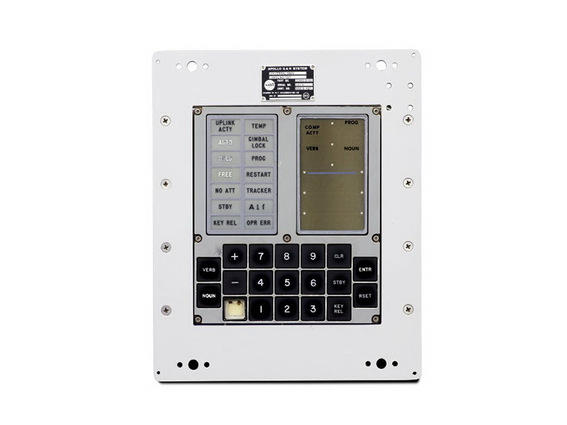
The AGC user interface consisted of 7-segment numbers displayed on the panel and banners and a keyboard similar to a calculator's keyboard. Commands were entered in digital mode as two-digit numbers: action and object. The action described the type of operation being performed, and the object defined the data for operation.
The numbers in green were displayed on seven-segment high-voltage indicators. Indicator segments were controlled by electromechanical relays. The display could simultaneously display three numbers of five digits in each, the display format could be either octal or decimal, and was used mainly to display the spacecraft position vectors or the required velocity change (ΔV). Although the data were stored in the metric system, they were displayed in the system adopted in the United States in those years.
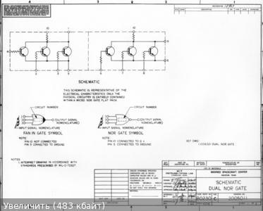
An example of the internal structure of the chip
Further, the signal from the generator is not used directly, but is divided into 4, which gives us a frequency of 512 kHz - this is the main frequency with which the computer registers are updated. But this action does not end the signal (512 kHz) divided by 5, we get a frequency of 102.4 kHz, which was further divided several times with a divider with a variable division factor to obtain a frequency of 100 Hz - this frequency was used for timers and system clocks. Further, the 1 Hz signal used in the system clock is divided up to obtain a frequency of 0.78125 Hz, which is designed to periodically poll the so-called Watch Dog Timer (WDT - Watch Dog Timer), which checks whether the processor unit is “stuck” and, if a hangup occurs, interrupts the power supply processor block, without affecting the memory registers.
AGC was created by scientists and engineers at the laboratory at the Massachusetts Institute of Technology instruments for the Apollo program. He led the development of Charles Stark Draper, and the chief designer of the hardware was Eldon Hall. Initial investigations were conducted by: Lanning Junior, Albert Hopkins, Ramon Alonso, and Hugues Blair-Smith. Serial production was carried out by Raytheon, and its representative, Herb Taeler, was included in the development team.
The computer used 2,800 microcircuits, each of which contained two elements exclusive OR. The clock frequency was 2 MHz. Weighed model 250 kg.
The computer's memory consisted of 2048 words of rewritable RAM and 36 KB of ROM words with a linear sample on repeatedly stitched cores. The read / write cycle of RAM and ROM took 11.72 μs. The word length was 16 bits.
From the point of view of the programmer of the ALU computer has four 16-bit registers:
A - register-battery, used for basic calculations.
Z is the command counter that stored the address of the next program to be executed.
Q is the remainder when executing the DV command (division), and the address of the return point after executing the TC command (unconditional jump).
LP - the younger part of the product when executing the command MP (multiplication), the older part was stored in register A.
The AGC user interface consisted of 7-segment numbers displayed on the panel and banners and a keyboard similar to a calculator's keyboard. Commands were entered in digital mode as two-digit numbers: action and object. The action described the type of operation being performed, and the object defined the data for operation.
The numbers in green were displayed on seven-segment high-voltage indicators. Indicator segments were controlled by electromechanical relays. The display could simultaneously display three numbers of five digits in each, the display format could be either octal or decimal, and was used mainly to display the spacecraft position vectors or the required velocity change (ΔV). Although the data were stored in the metric system, they were displayed in the system adopted in the United States in those years.
An example of the internal structure of the chip
Further, the signal from the generator is not used directly, but is divided into 4, which gives us a frequency of 512 kHz - this is the main frequency with which the computer registers are updated. But this action does not end the signal (512 kHz) divided by 5, we get a frequency of 102.4 kHz, which was further divided several times with a divider with a variable division factor to obtain a frequency of 100 Hz - this frequency was used for timers and system clocks. Further, the 1 Hz signal used in the system clock is divided up to obtain a frequency of 0.78125 Hz, which is designed to periodically poll the so-called Watch Dog Timer (WDT - Watch Dog Timer), which checks whether the processor unit is “stuck” and, if a hangup occurs, interrupts the power supply processor block, without affecting the memory registers.