FLProg + Nextion HMI. Lesson 3
- Tutorial
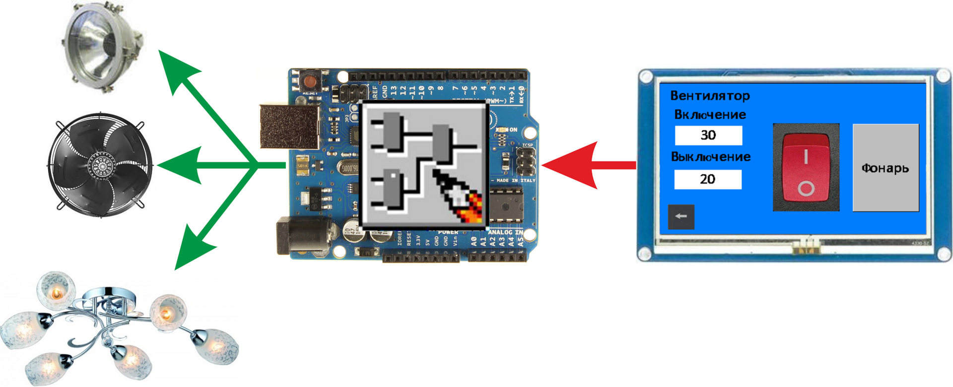
In previous lessons ( lesson 1 , lesson 2 ), I explained how to draw the interface of the Nextion HMI panel, how to control the panel with the Arduino. In this tutorial, I’ll show you how to solve the inverse problem — control the Arduino board using the Nextion HMI panel.
In the lesson, we will expand the draft of the previous lesson, add fan control, which will turn on when the temperature exceeds the specified limit, and turn off when the temperature drops below the second limit. The settings will be set from the panel and stored in the non-volatile memory of the Arduino controller. In addition, we will make a light switch on the panel (two-way) and a button with which we will turn on the flashlight (for example, to give a signal to aliens).
Modified scheme from the last lesson. The lantern, the light and the fan will mimic the LEDs.

Also the project of the panel is improved. Added two pages. In addition, the font loaded in the panel has been replaced. The project for the panel is in the archive, a link to which is given at the end of the article. In the comments to the past lesson, I was quite rightly scolded for the lack of design talent. I completely agree with this, so the new pages have no design, pure functionality.
Consider new pages.
Management page (“page3”, ID = 3).

Consider the items on the page.
- Just text fields. Nothing interesting.
- Field display setpoint fan on. As I already wrote, the panel does not know how to work with fractional numbers. Therefore, these are text fields. The row for display will be prepared on arduinka. Item Parameters
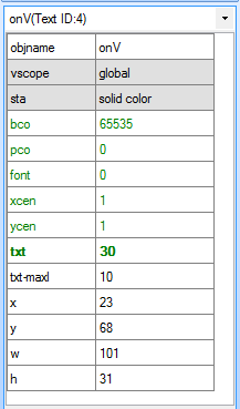
Since the value in this field will be sent from the controller, we make it global (the “vscope” attribute is set to “global”). Clicking on this field will open the value edit page. Therefore, the following code is recorded in the “Touch Press Event” event.
When you click on an element, first in the editable value field on page 4 we enter the current value.page4.evtemp.txt=onV.txt
Then in the variable that stores the identifier of the editable field on page 4, enter the identifier of the field by which you clicked.page4.varN.val=0
Well, go to the edit value page.page page4 - Display field setting off the fan. Almost identical to the previous field. Item Parameters

The code in the event “Touch Press Event”.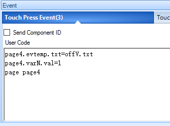
In this code, the difference from the previous one is only in the field identifier.page4.varN.val=1 - Button back. Copied from the last lesson. Item Parameters
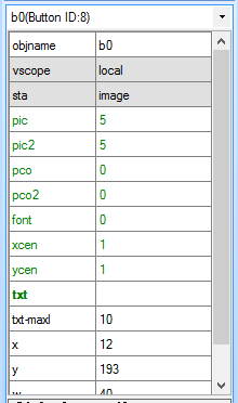
The code in the event “Touch Press Event”.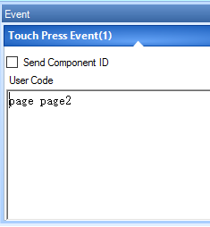
- Two position switch (“Dual-state button”) - light control.
Item Parameters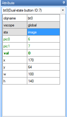
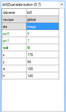
The state value of this element will be read from the controller, therefore the global element (the “vscope” attribute and the value “global”). As the background display mode, the image mode is selected (the “sta” attribute is “image”). Pictures are set in the attributes “pic0” for state 0 and “pic1” for state 1. - Button (“Button”) - turn on the flashlight. Item Parameters
We will stop here in more detail. We will monitor the button presses from the controller to control the lamp. Unfortunately, in Arduino it is impossible to set an interruption to receive a byte from the UART (at least by means of standards). Therefore, we had to implement memorization of the fact of pressing and releasing the button using two variables (7 and 8). We will not directly apply to the button, so it can be done both locally and globally (I made it global just in case). The following code is written in the button click handler (“Touch Press Event”).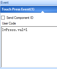
And in the button release handler (“Touch Release Event”) such.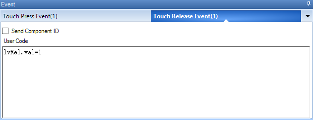
We will need these variables in the click tracking block in the FLProg project.
Edit value window (“page4”, ID = 4).
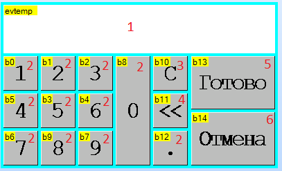
Consider what is included in it.
- Editable value field. Item Parameters

The value of this field will be read from the controller, accordingly we make it global (the “vscope” attribute is set to “global”). - Value entry buttons. All these buttons are almost identical, and differ in the inscription and code in the event handler “Touch Press Event”. When you click on one of these buttons, the corresponding symbol is added to the current value of the editable value field.The code in the event “Touch Press Event” for each of the buttons.“0”
evtemp.txt=evtemp.txt+"0"
“1”evtemp.txt=evtemp.txt+"1"
“2”evtemp.txt=evtemp.txt+"2"
“3”evtemp.txt=evtemp.txt+"3"
“4”evtemp.txt=evtemp.txt+"4"
“5”evtemp.txt=evtemp.txt+"5"
“6”evtemp.txt=evtemp.txt+"6"
“7”evtemp.txt=evtemp.txt+"7"
“8”evtemp.txt=evtemp.txt+"8"
“9”evtemp.txt=evtemp.txt+"9"
“.”evtemp.txt=evtemp.txt+"." - Button to clear the field. Pressing it deletes the field value.
The code in the event “Touch Press Event”evtemp.txt="" - Button to delete the last character.
The code in the event “Touch Press Event”evtemp.txt=evtemp.txt-1
This is not a documented feature. It deletes the last character in the string. I spied it on one of the videos on the manufacturer's website. In general, I did not find almost any information on working with strings on the panel. - Button to finish editing the value.
Pressing this button will be tracked on the controller, so two variables are created for it (“endPress” and “endRel”) and the code is written in the event handlers.
The code in the event “Touch Press Event”page4.endPress.val=1
The code in the event “Touch Release Event”page4.endRel.val=1 - Cancel button. By pressing this button, we simply return to the control page.
The code in the event “Touch Press Event”page page3
With the panel finished, go to the FLProg program. It also uses a project from the last lesson a little modified. The project file is in the archive, the link to which is given at the end of the post.
As in the last lesson, I will show the finished circuit diagrams and tell what is happening on them.
Fee 7 - "Lantern Management"

Everything is simple. Block B46 - “Click Tracking” (library of elements, folder “Nextion HMI Panel”). At its output, it has a value corresponding to the state of the monitored button or another element of the panel having the “Touch Press Event” and “Touch Release Event”. This value is directly recorded in the exit tied to the lamp. The block is parameterized using the block editor.

In the block editor, you need to select a panel, and then create a new page and write the necessary elements on it. How to do this, I told in the previous lesson.
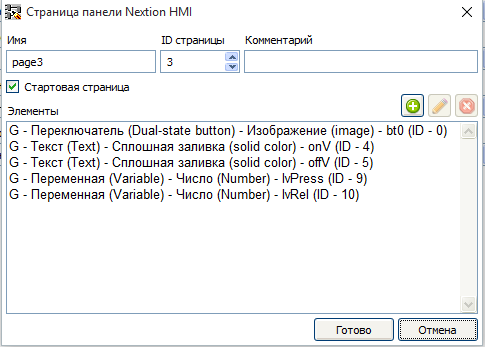
You should get this picture.
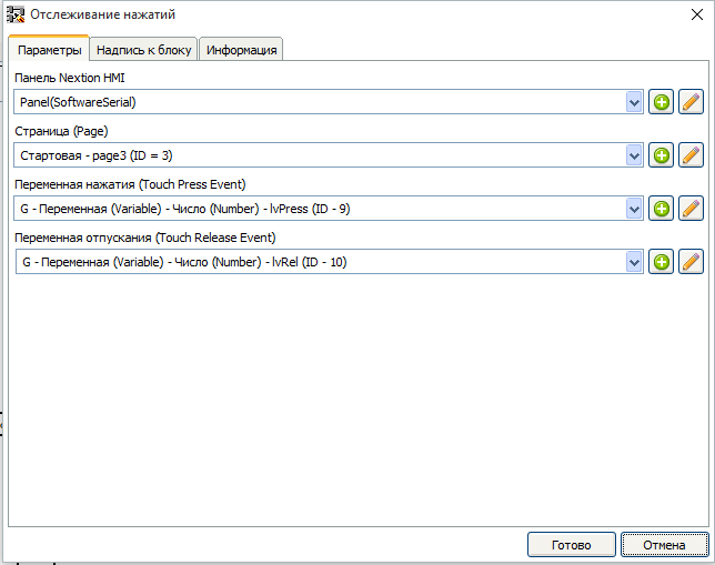
As a pressing variable, select the variable to which we write the unit in the “Touch Press Event” button, and as the release variable, the variable from the “Touch Release Event” button.
Fee 8 - "Control of the light."
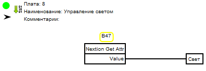
Same very simple fee. Here we read the switch position using the block B47 - “Get Parameter” (element library -> Nextion HMI Panel folder -> Elements folder). This value is then sent directly to the output block tied to the lighting. The block is parameterized using the block editor.
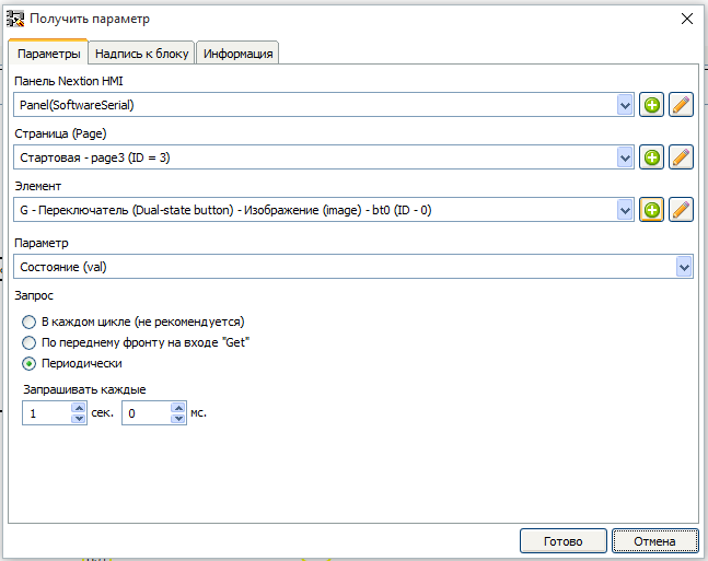
To reduce the load on the controller, we will make a request for the state of the switch once a second.
Board 9 - "The end of editing parameters."
On this board, we will process the click on the “Finish” button on the parameter edit page.
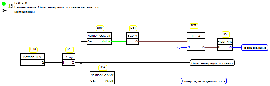
Using the block B48 - “Track clicks” (library of elements, folder “Nextion HMI Panel”), we determine the moment of clicking. In the editor of this block, we will create page 4 and fill it with elements of interest to us.
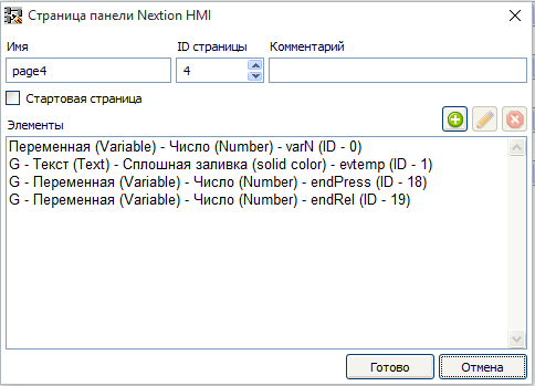
And configure the block.

Using block В49 - “Rtrig” (library of elements, “Triggers” folder), select the leading edge of the signal when the “Finish” button is pressed and write to the variable “Editing end”.
Also on this front, we read the value of the variable that stores the identifier of the editable field using block B54 - “Get Parameter” (element library -> Nextion HMI Panel folder -> Elements folder). Block settings.
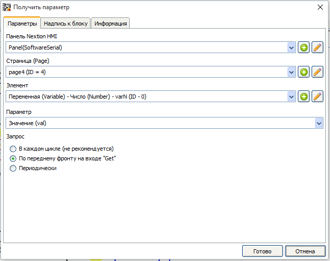
The resulting value is set to the variable "Editable field number".
And for the same impulse, we will directly read the new value from the text field using the B50 block - - “Get Parameter” (element library -> Nextion HMI Panel folder -> Elements folder). Block settings.
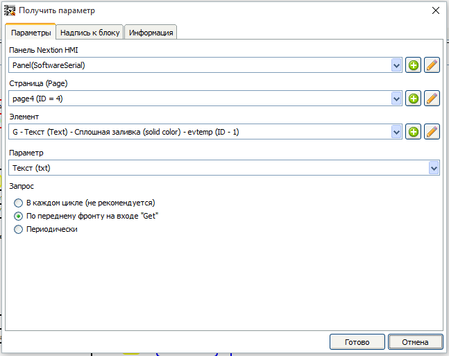
We transform the new value from the string into a number in the Float format using block B51 - “String Conversion” (library of elements, “Type Conversion” folder). Block settings.

Multiply the number by 10 using the block B52 - “MUL (*)” (library of elements, “Mathematics” folder), change the type to Integer using the block B53 - “Convert Float to Integer” (library of elements, “Conversion of types” folder) and put in the variable "New value".
Fee 10 - "Processing the results of editing values"
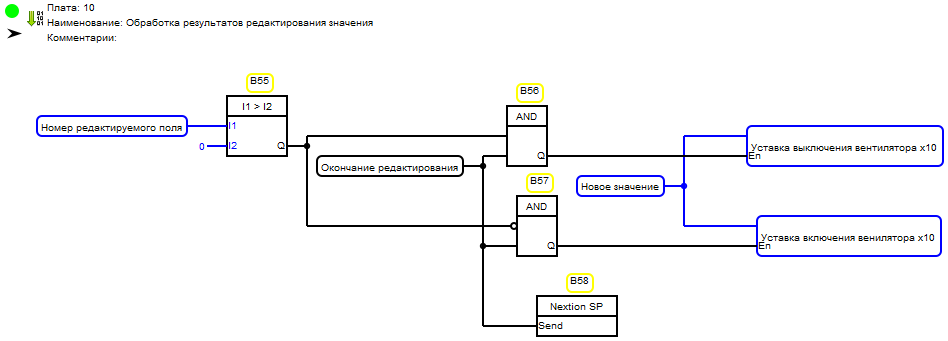
Using the block B55 - “Comparator” (library of elements, folder “Comparison”) we determine which field was edited and, depending on the result, write the value from the variable “New value” by impulse in the variable “Editing end” to one of two variables, in the "fan off setting x10" or in the "fan on setting x10". Also for the same impulse, we give the panel command to go to the control page using the B58 block “Go to page” (library of elements, folder “Nextion HMI Panel” -> “Page” folder). Block settings.

Fee 11 - “Recording Setting Values to the Panel and EEProm”
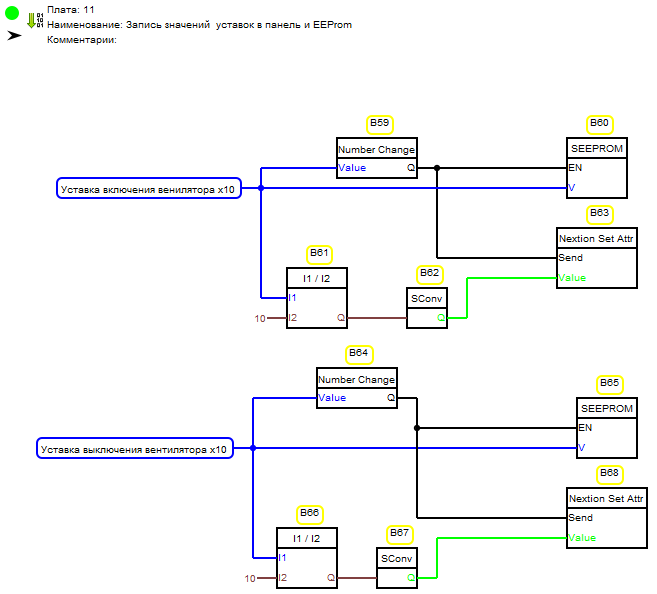
With the help of block В59 - “Number change detector” (library of elements, folder “Basic elements”) we determine the fact of changing the value of the variable “Fan activation setting x10”. At the output of the block, a short pulse is formed at the moment of changing the value at the input “Value”. This impulse records the value to the non-volatile memory of the controller. This happens with the help of block B65 - “Write to EEPROM” (library of elements, folder “EEPROM”). The block is configured using the block editor.
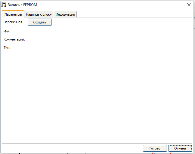
Before writing a variable in the EEPROM, you need to create it there. To do this, click the "Create" button in the block editor. The variable creation window opens.
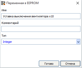
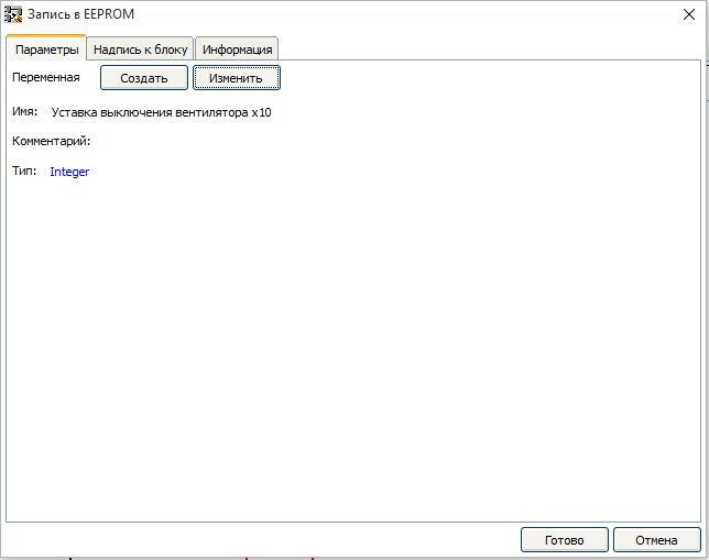
In it we set the name of the variable and its type. After pressing the button, the block is ready to be bound to this variable.
Also, by the signal of a variable change, its value is divided into a constant of type Float equal to 10 with the help of block В61 - “DIV (/)” (library of elements, “Mathematics” folder), turns into a string with the help of block B62 - “String conversion” (library of elements, folder “type conversion”), and is sent to the panel in the appropriate field using block B63 - “Set Parameter” (library of elements, folder “Nextion HMI Panel” -> Elements folder). Settings of this unit.
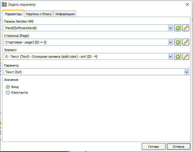
The logic of the variable control “Setting the fan off x10” is similar, the settings of the blocks are as follows.
Block b65.

Block B68.

Now we will ensure reading the settings from the EEPROM at the time of the controller start. To do this, we insert a new board at the very top of the project so that the scheme located on it is executed first. To do this, select the first plan and click the button "Insert board before the selected one".
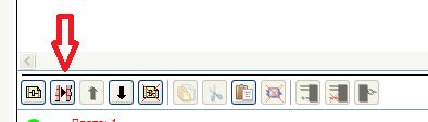
Let's call the new board “Reading settings from EEPROM”. Board
1.
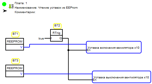
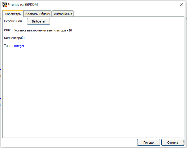
With the help of block B72 - “Rtrig” (library of elements, folder “Triggers”) we create one short impulse when the controller is turned on. According to this impulse, the values read from the non-volatile memory are written to the variables “Fan on setpoint x10” and “Fan off point x10”. This happens with the help of blocks B71 and B73 - “Reading from EEPROM” (library of elements, “EEPROM” folder). Blocks are parameterized using the block editor.
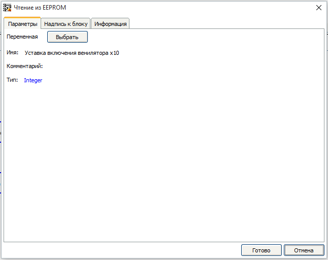
Parameters block B71.
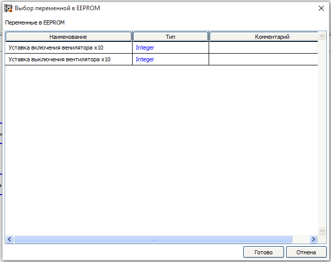
The choice of a readable variable in the EEPROM is made by pressing the “Select” button. The variable selection window opens.

Parameters block B73.
Well, the last board in the project.
Board 12. “Fan control”
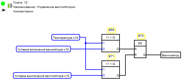
If the current temperature exceeds the setpoint “Fan On Setpoint x10” this will detect the comparison unit B69 and set trigger B70 to state 1, and when the temperature drops below the setpoint “Fan Off Setpoint x10” it will be detected by Block B71, which sets the B70 trigger to the state 0. The trigger state is fed to the output unit associated with the fan.
Archive with source code of projects.
Video demonstration