Software Defined Radio - how does it work? Part 7
Hi, Habr.
In the previous part about transmission to GNU Radio , the question was asked about whether it is possible to decode the LoRa protocol (data transfer for low-power devices) using SDR. This topic seemed interesting to me, especially since the LoRa signal itself is rather unusual - the so-called Chirp Spread Spectrum modulation, or “chirp modulation”.
How it works, continued under the cut.
By the way, the literal translation of Chirp modulation would have sounded like “tweet modulation,” but that sounds completely surreal, so I'd rather leave the simple word “chirp” (as suggested in the comments, in Russian this is called linear-frequency modulation ).
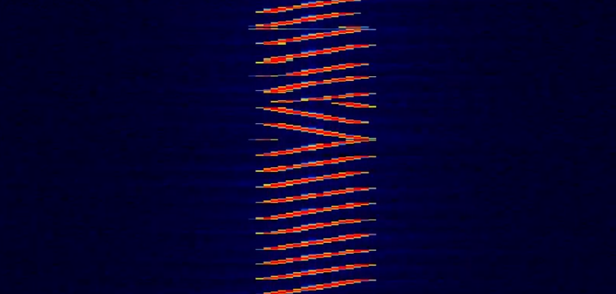
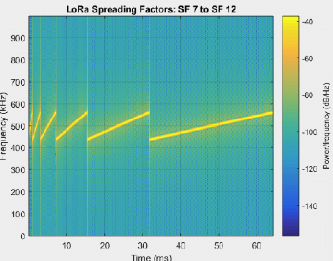
As mentioned above, when transmitting LoRa, a modulation method using “chirps” is used, by the way patented by Semtech. If anyone wants implementation details with formulas, you can read the PDF on the semtech website or here , but if it’s very rude, then one “chirp” is one frequency change, and the bit stream is encoded with such changes, as shown in the picture above. Signal parameters in LoRa are SF (spreading factor - in fact, the duration of one "chirp") and bandwidth - transmission bandwidth. The SF parameter is set by the predefined SF7 values - SF12, where 7 is the fastest and 12 is the slowest mode (for example, you can see a picture with an illustration of different speeds of chirping with researchgate ).
Obviously, the shorter the length of the “chirp” and the wider the band, the more you can get the transmission speed. All this is connected with approximately the following table:

From the point of view of range and noise immunity, it is advantageous to transmit slowly and sadly, but at the same time we lose speed, secondly, we lose time, and according to LoRa rules, a device can transmit no more than 1 % of the time so as not to interfere with other devices. So the choice of the optimal transmission speed for low-power devices is also not an easy task.
With a general principle, I hope it’s clear, now let's move on to SDR and decoding.
For testing, I used the LoRa Click RN2483 and Arduino M0, simply because they were available.

This is a fairly convenient form factor for prototyping, as it allows you to easily replace the board one with another without soldering (in this format, called MikroBUS , many different peripherals are available).
The draft code, not pretending to be production, has been added under the spoiler. The value "1234" is passed as a test.
By the way, the maximum declared transmission range for RN2483 is up to 15 km, in practice, in the presence of a one-story building, the signal disappears already for 1 km, and can be no more than 100 m in urban "anthills".
We start the modem, and proceed to decoding.
There is no LoRa support in GNU Radio itself, so you have to use third-party components. There were only two of them, and unfortunately, both authors did not show any imagination in the name, and they called them exactly the same - gr-lora ( https://github.com/rpp0/gr-lora and https://github.com/ BastilleResearch / gr-lora respectively). Unfortunately, because GNU Radio cannot have both components at once, the installer of one component overwrites the files of the other.
rpp0 / gr-lora
You can download the decoder sources from github , the assembly is standard and does not cause difficulties:
After installation, additional blocks appear in GNU Radio, from which it is easy to assemble a decoder. As the parameters of the decoder, you must specify the transmission bandwidth, spreading factor, the center frequency of the SDR and the reception frequency.

The units in GNU Radio are standardized so that any receiver, such as RTL-SDR, can be used. I used SDRPlay. A simple Python program was used to output data to the console.
The result of the work is shown in the figure.
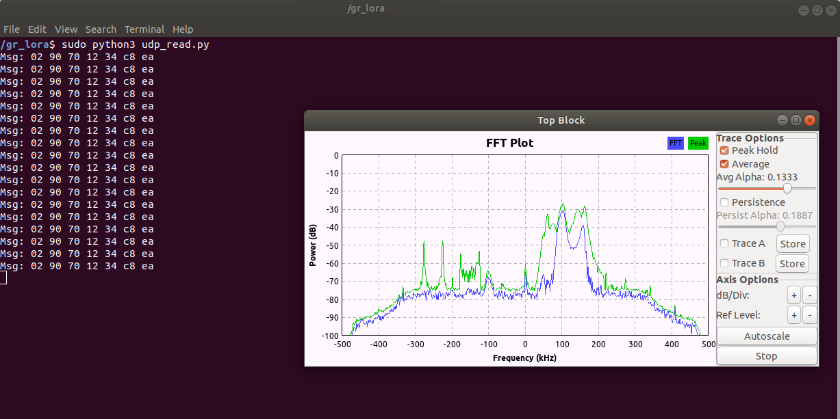
As you can see, the row contains the header and end blocks of the transmission, and in the middle we see our data “1234”.
BastilleResearch / gr-lora
This module is notable for the fact that it can work not only on reception, but also on transmission. The installation is about the same: the component needs to be assembled from source.
The Connection Graph for this decoder is shown in the figure.
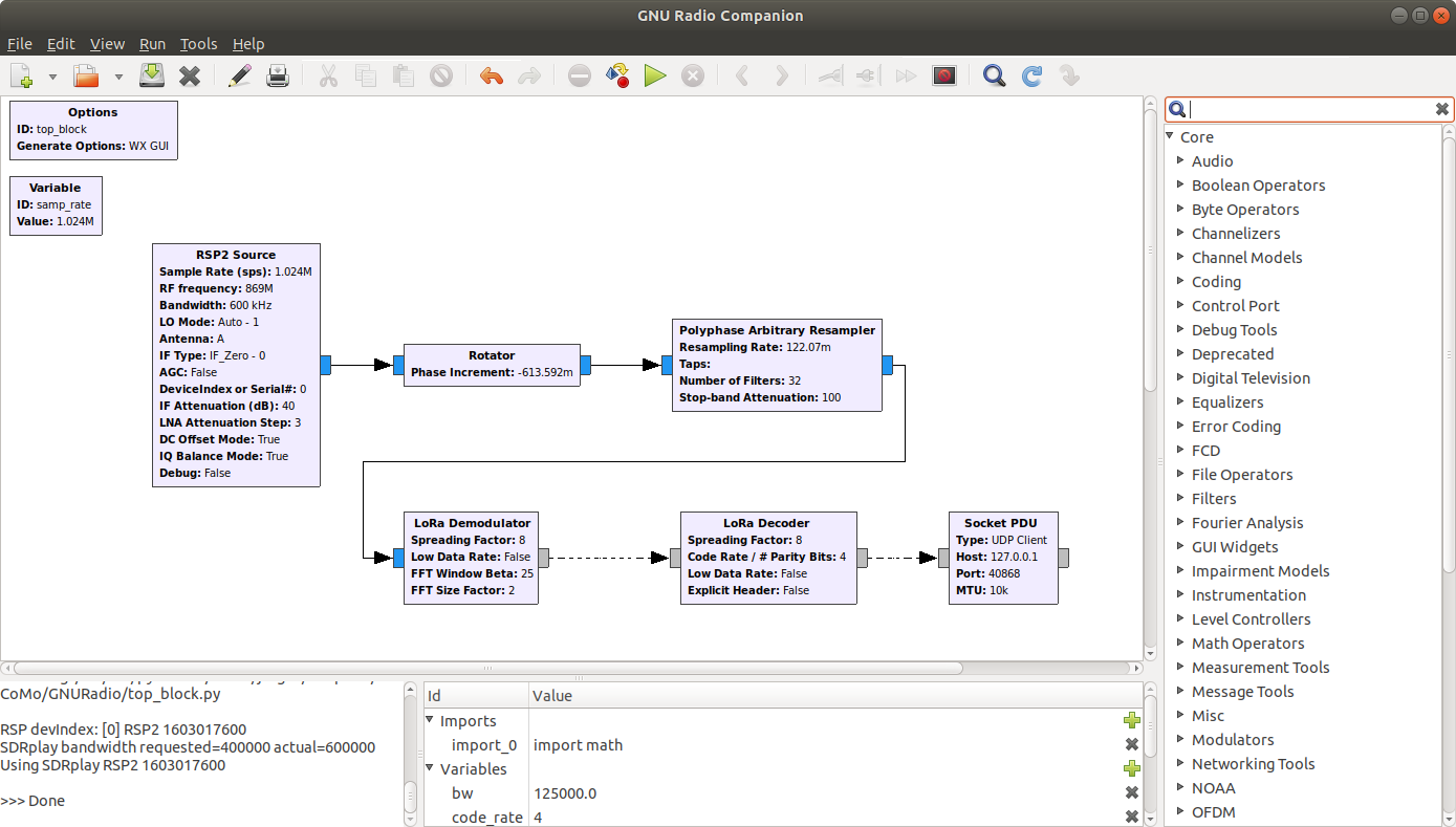
As you can see, there are more blocks. Rotator and Polyphase Resampler select the desired frequency and cut off the excess, the Demodulator converts the “chirps” into a binary code (the output is a sequence like “17 00 3e 00 38 00 2f 00 01 00 39 00 2c 00 30 00 c6 00 18 00 7e 00 d5 00 85 00 e9 00 d8 00 67 00 c4 00 ”), and Decoder forms the final package.
Unfortunately, it never worked properly. Decoding definitely works, while the modem is working, the data appears, but the received messages have nothing to do with the transmitted ones.

I did not understand the reason, either I made a mistake in the settings somewhere, or this decoder is compatible only with my own encoder. Those who wish can check independently using the Channel Model.
As you can see, the lower, physical layer of transmission was considered here. In the higher-level LoRaWAN protocol, another logical layer is placed on top - with encryption, keys and other services. Those who want to see how encoding works can try the online decoder here .
By the way, it follows that even if we receive a LoRaWAN signal using SDR, without the presence of encryption keys (one of which is stored on the provider's server), we still do not recognize the contents of the packet.
As you can see, decoding LoRa using SDR is quite possible. Of course, making a real gateway based on SDR is hardly advisable - its sensitivity will be worse than the sensitivity of "real" modems, which are specially designed to receive weak signals, and have more narrow-band filters and LNA. But for testing or research, this can be quite interesting.
For those who want to try it on their own, the GNU Radio source grc files are under the spoiler.
All successful experiments.
In the previous part about transmission to GNU Radio , the question was asked about whether it is possible to decode the LoRa protocol (data transfer for low-power devices) using SDR. This topic seemed interesting to me, especially since the LoRa signal itself is rather unusual - the so-called Chirp Spread Spectrum modulation, or “chirp modulation”.
How it works, continued under the cut.
By the way, the literal translation of Chirp modulation would have sounded like “tweet modulation,” but that sounds completely surreal, so I'd rather leave the simple word “chirp” (as suggested in the comments, in Russian this is called linear-frequency modulation ).
LoRa Modulation
As mentioned above, when transmitting LoRa, a modulation method using “chirps” is used, by the way patented by Semtech. If anyone wants implementation details with formulas, you can read the PDF on the semtech website or here , but if it’s very rude, then one “chirp” is one frequency change, and the bit stream is encoded with such changes, as shown in the picture above. Signal parameters in LoRa are SF (spreading factor - in fact, the duration of one "chirp") and bandwidth - transmission bandwidth. The SF parameter is set by the predefined SF7 values - SF12, where 7 is the fastest and 12 is the slowest mode (for example, you can see a picture with an illustration of different speeds of chirping with researchgate ).
Obviously, the shorter the length of the “chirp” and the wider the band, the more you can get the transmission speed. All this is connected with approximately the following table:
From the point of view of range and noise immunity, it is advantageous to transmit slowly and sadly, but at the same time we lose speed, secondly, we lose time, and according to LoRa rules, a device can transmit no more than 1 % of the time so as not to interfere with other devices. So the choice of the optimal transmission speed for low-power devices is also not an easy task.
With a general principle, I hope it’s clear, now let's move on to SDR and decoding.
Iron
For testing, I used the LoRa Click RN2483 and Arduino M0, simply because they were available.
This is a fairly convenient form factor for prototyping, as it allows you to easily replace the board one with another without soldering (in this format, called MikroBUS , many different peripherals are available).
The draft code, not pretending to be production, has been added under the spoiler. The value "1234" is passed as a test.
rn2483_tx.ino
// RN2483 Modem and LoRa Click test TX. Tested with Arduino M0
int reset = A2;
int rts = 9; // CS
int cts = 3; // INT
// the setup routine runs once when you press reset:
void setup()
{
    Serial1.begin(57600); // Serial port to radio
    // output LED pin
    pinMode(LED_BUILTIN, OUTPUT);
    pinMode(cts, INPUT);
    pinMode(rts, OUTPUT);
    digitalWrite(rts, HIGH);
    // Reset rn2483
    pinMode(reset, OUTPUT);
    digitalWrite(reset, LOW);
    delay(100);
    digitalWrite(reset, HIGH);
    delay(100);
    sendCommand("sys get ver\r\n");
    sendCommand("sys get hweui\r\n");
    sendCommand("mac pause\r\n");
    sendCommand("radio set mod lora\r\n");
    sendCommand("radio set pwr -3\r\n"); // the transceiver output power, from -3 to 15
    sendCommand("radio set sf sf8\r\n"); // sf7..sf12, sf7 the fastest spreading factor but gives the shortest range
    // sendCommand("mac set dr 0\r\n"); // data rate: 0-4, 4 faster
    sendCommand("radio set freq 869100000\r\n");
    // sendCommand("radio set afcbw 41.7\r\n");
    sendCommand("radio set rxbw 125\r\n");
    // sendCommand("radio set prlen 8\r\n");
    sendCommand("radio set crc on\r\n");
    // sendCommand("radio set iqi off\r\n");
    sendCommand("radio set cr 4/8\r\n");
    // sendCommand("radio set wdt 60000\r\n"); // disable for continuous reception
    // sendCommand("radio set sync 12\r\n");
    sendCommand("radio set bw 125\r\n");
}
void sendCommand(const char *cmd)
{
    Serial1.print(cmd);
    String incoming = Serial1.readString();
    // SerialUSB.print(cmd);
    // SerialUSB.println(incoming);
}
// the loop routine runs over and over again forever:
void loop()
{
    char data[64] = {0};
    //  hexadecimal value representing the data to be transmitted, from 0 to 255 bytes for LoRa modulation and from 0 to 64 bytes for FSK modulation.
    sprintf(data, "radio tx 1234\r\n");
    sendCommand(data);
    if (msg_num > 10000) msg_num=0;
    digitalWrite(LED_BUILTIN, 1);
    delay(400);
    digitalWrite(LED_BUILTIN, 0);
    delay(600);
}
By the way, the maximum declared transmission range for RN2483 is up to 15 km, in practice, in the presence of a one-story building, the signal disappears already for 1 km, and can be no more than 100 m in urban "anthills".
We start the modem, and proceed to decoding.
Decoding
There is no LoRa support in GNU Radio itself, so you have to use third-party components. There were only two of them, and unfortunately, both authors did not show any imagination in the name, and they called them exactly the same - gr-lora ( https://github.com/rpp0/gr-lora and https://github.com/ BastilleResearch / gr-lora respectively). Unfortunately, because GNU Radio cannot have both components at once, the installer of one component overwrites the files of the other.
rpp0 / gr-lora
You can download the decoder sources from github , the assembly is standard and does not cause difficulties:
git clone https://github.com/rpp0/gr-lora.git
cd gr-lora
mkdir build
cd build
cmake ..
make && sudo make install && sudo ldconfig
After installation, additional blocks appear in GNU Radio, from which it is easy to assemble a decoder. As the parameters of the decoder, you must specify the transmission bandwidth, spreading factor, the center frequency of the SDR and the reception frequency.
The units in GNU Radio are standardized so that any receiver, such as RTL-SDR, can be used. I used SDRPlay. A simple Python program was used to output data to the console.
udp_receive.py
import socket
UDP_IP = "127.0.0.1"
UDP_PORT = 40868
sock = socket.socket(socket.AF_INET, socket.SOCK_DGRAM) # UDP
sock.setsockopt(socket.SOL_SOCKET, socket.SO_REUSEADDR, 1)
sock.bind((UDP_IP, UDP_PORT))
sock.settimeout(0.5)
while True:
    try:
        data, addr = sock.recvfrom(128) # buffer size is 1024 bytes
        print("Msg:", ' '.join('{:02x}'.format(x) for x in data))
    except socket.timeout:
        pass
The result of the work is shown in the figure.
As you can see, the row contains the header and end blocks of the transmission, and in the middle we see our data “1234”.
BastilleResearch / gr-lora
This module is notable for the fact that it can work not only on reception, but also on transmission. The installation is about the same: the component needs to be assembled from source.
git clone git://github.com/BastilleResearch/gr-lora.git
cd gr-lora
mkdir build
cd build
cmake ..
make && sudo make install && sudo ldconfig
The Connection Graph for this decoder is shown in the figure.
As you can see, there are more blocks. Rotator and Polyphase Resampler select the desired frequency and cut off the excess, the Demodulator converts the “chirps” into a binary code (the output is a sequence like “17 00 3e 00 38 00 2f 00 01 00 39 00 2c 00 30 00 c6 00 18 00 7e 00 d5 00 85 00 e9 00 d8 00 67 00 c4 00 ”), and Decoder forms the final package.
Unfortunately, it never worked properly. Decoding definitely works, while the modem is working, the data appears, but the received messages have nothing to do with the transmitted ones.
I did not understand the reason, either I made a mistake in the settings somewhere, or this decoder is compatible only with my own encoder. Those who wish can check independently using the Channel Model.
LoRaWAN
As you can see, the lower, physical layer of transmission was considered here. In the higher-level LoRaWAN protocol, another logical layer is placed on top - with encryption, keys and other services. Those who want to see how encoding works can try the online decoder here .
By the way, it follows that even if we receive a LoRaWAN signal using SDR, without the presence of encryption keys (one of which is stored on the provider's server), we still do not recognize the contents of the packet.
Conclusion
As you can see, decoding LoRa using SDR is quite possible. Of course, making a real gateway based on SDR is hardly advisable - its sensitivity will be worse than the sensitivity of "real" modems, which are specially designed to receive weak signals, and have more narrow-band filters and LNA. But for testing or research, this can be quite interesting.
For those who want to try it on their own, the GNU Radio source grc files are under the spoiler.
receive1.grc
Mon Jun 3 09:39:45 2019 options author window_size category [GRC Hier Blocks] comment description _enabled True _coordinate (8, 8) _rotation 0 generate_options wx_gui hier_block_src_path .: id top_block max_nouts 0 qt_qss_theme realtime_scheduling run_command {python} -u {filename} run_options prompt run True thread_safe_setters title variable comment _enabled True _coordinate (760, 12) _rotation 0 id bw value 125000.0 variable comment _enabled 1 _coordinate (936, 12) _rotation 0 id code_rate value 4 variable comment _enabled 1 _coordinate (848, 12) _rotation 0 id header value True variable comment _enabled 1 _coordinate (680, 12) _rotation 0 id ldr value True variable comment _enabled True _coordinate (400, 12) _rotation 0 id offset value -100000.0 variable comment _enabled True _coordinate (8, 76) _rotation 0 id samp_rate value 1000000 variable comment _enabled 1 _coordinate (544, 12) _rotation 0 id spreading_factor value 8 blocks_rotator_cc alias comment affinity _enabled 1 _coordinate (416, 252) _rotation 0 id blocks_rotator_cc_0 maxoutbuf 0 minoutbuf 0 phase_inc (2 * math.pi * offset) / samp_rate blocks_socket_pdu alias comment affinity _enabled 1 _coordinate (944, 452) _rotation 0 host 127.0.0.1 id blocks_socket_pdu_0 mtu 10000 maxoutbuf 0 minoutbuf 0 port 40868 tcp_no_delay False type "UDP_CLIENT" import alias comment _enabled True _coordinate (296, 12) _rotation 0 id import_0 import import math lora_decode alias code_rate code_rate comment affinity _enabled 1 header header _coordinate (648, 452) _rotation 0 id lora_decode_0 low_data_rate ldr maxoutbuf 0 minoutbuf 0 spreading_factor spreading_factor lora_demod alias comment affinity _enabled 1 fft_factor 2 beta 25.0 _coordinate (384, 452) _rotation 0 id lora_demod_0 low_data_rate ldr maxoutbuf 0 minoutbuf 0 spreading_factor spreading_factor pfb_arb_resampler_xxx alias comment affinity _enabled 1 _coordinate (656, 292) _rotation 0 id pfb_arb_resampler_xxx_0 maxoutbuf 0 minoutbuf 0 nfilts 32 rrate bw/samp_rate samp_delay 0 atten 100 taps type ccf sdrplay_rsp2_source agc_enabled False antenna 'A' bw 400 alias comment affinity dc_offset_mode True debug_enabled False device_serial '0' _enabled True _coordinate (144, 196) _rotation 0 id sdrplay_rsp2_source_0 if_atten_db 30 ifType 0 iq_balance_mode True lna_atten_step 3 lo_mode 1 maxoutbuf 0 minoutbuf 0 rf_freq 869.0e6 sample_rate samp_rate wxgui_fftsink2 avg_alpha 0 average False baseband_freq 0 alias comment affinity _enabled True fft_size 1024 freqvar None _coordinate (1000, 116) _rotation 0 grid_pos id wxgui_fftsink2_0 notebook peak_hold False ref_level 0 ref_scale 2.0 fft_rate 15 samp_rate samp_rate title FFT Plot type complex win_size win None y_divs 10 y_per_div 10 blocks_rotator_cc_0 pfb_arb_resampler_xxx_0 0 0 blocks_rotator_cc_0 wxgui_fftsink2_0 0 0 lora_decode_0 blocks_socket_pdu_0 out pdus lora_demod_0 lora_decode_0 out in pfb_arb_resampler_xxx_0 lora_demod_0 0 0 sdrplay_rsp2_source_0 blocks_rotator_cc_0 0 0 receive2.grc
Mon Jun 3 09:39:45 2019 options author window_size category [GRC Hier Blocks] comment description _enabled True _coordinate (8, 8) _rotation 0 generate_options wx_gui hier_block_src_path .: id top_block max_nouts 0 qt_qss_theme realtime_scheduling run_command {python} -u {filename} run_options prompt run True thread_safe_setters title variable comment _enabled True _coordinate (184, 12) _rotation 0 id samp_rate value 1000000 lora_lora_receiver bandwidth 125000 alias crc True center_freq 869e6 channel_list [869.1e6] cr 4 comment conj False affinity decimation 1 disable_channelization False disable_drift_correction False _enabled True _coordinate (456, 332) _rotation 0 id lora_lora_receiver_0 implicit False maxoutbuf 0 minoutbuf 0 reduced_rate False samp_rate 1e6 sf 8 lora_message_socket_sink alias comment affinity _enabled True _coordinate (696, 364) _rotation 0 id lora_message_socket_sink_0 ip 127.0.0.1 layer 1 port 40868 sdrplay_rsp2_source agc_enabled False antenna 'A' bw 400 alias comment affinity dc_offset_mode True debug_enabled False device_serial '0' _enabled True _coordinate (72, 148) _rotation 0 id sdrplay_rsp2_source_0 if_atten_db 30 ifType 0 iq_balance_mode True lna_atten_step 3 lo_mode 1 maxoutbuf 0 minoutbuf 0 rf_freq 869.0e6 sample_rate samp_rate wxgui_fftsink2 avg_alpha 0 average True baseband_freq 0 alias comment affinity _enabled True fft_size 1024 freqvar None _coordinate (688, 108) _rotation 0 grid_pos id wxgui_fftsink2_0 notebook peak_hold True ref_level 0 ref_scale 2.0 fft_rate 15 samp_rate samp_rate title FFT Plot type complex win_size win None y_divs 10 y_per_div 10 lora_lora_receiver_0 lora_message_socket_sink_0 frames in sdrplay_rsp2_source_0 lora_lora_receiver_0 0 0 sdrplay_rsp2_source_0 wxgui_fftsink2_0 0 0 All successful experiments.