How to see reverberation or video transmission by sound through water - 2
Hello dear!
Today we will again transmit the picture with ultrasound through the water: we will literally see reverberation and echo, and even how they change depending on the conditions. All that I’ll tell you is simple, it’s interesting to repeat it myself and can be done by almost anyone.
If something is fluttering in your soul from these words, welcome to Kat, into the dark waters of our pond!

“The best rest is to interpret well-known truths.” (C) ABS, Noon, XXII Century
Prelude
The basic rule of the club of witnesses of hydroacoustics is that video using hydroacoustics at a more or less significant distance (more than a few meters) in the middle body of water cannot be transmitted, and always will not.
There are serious reasons for this - a communication channel with a very low bandwidth, a low signal propagation speed (in water only 1,500 m / s) and a high probability of error. The available frequency band is only a few tens of kilohertz.
But this is not all - if, relatively speaking, a signal at frequencies of the order of 10 kHz propagates in water at a distance of about 8-10 km, then at a frequency of 20 kHz it is already 3-5 km, and the higher the frequency, the stronger the attenuation . For example, our smallest uWAVE modems in the worldoperate in the 20-30 kHz band and transmit data at a speed of 78 bit / s per 1000 meters, and RedLINE with a band of 5-15 to 8000 meters. The record among commercial devices belongs to EvoLogics - 68 kBits per 300 meters.
Physics, alas, cannot be deceived and it is impossible to agree with it - it can be transmitted either very slowly and noise-immune, or quickly, but over short distances.
However, in some cases it is possible to “cut off some corners”, which corners we will cut this time are lower.
What will we do today and what is needed for this?
In previous articles, we already transmitted “video” with sound through water , I remind you that there the frame was “drawn on the spectrum”, that is, the spectrum, or rather the spectrogram of the signal was a picture.
Later we made simple hydroacoustic antennas from garbage and made the simplest hydroacoustic modem . There we also made a preamp for the antenna (the design of the PCB for self-production by LUT-ohm still lies here ).
We thought how else you can try to convey the picture so that even a
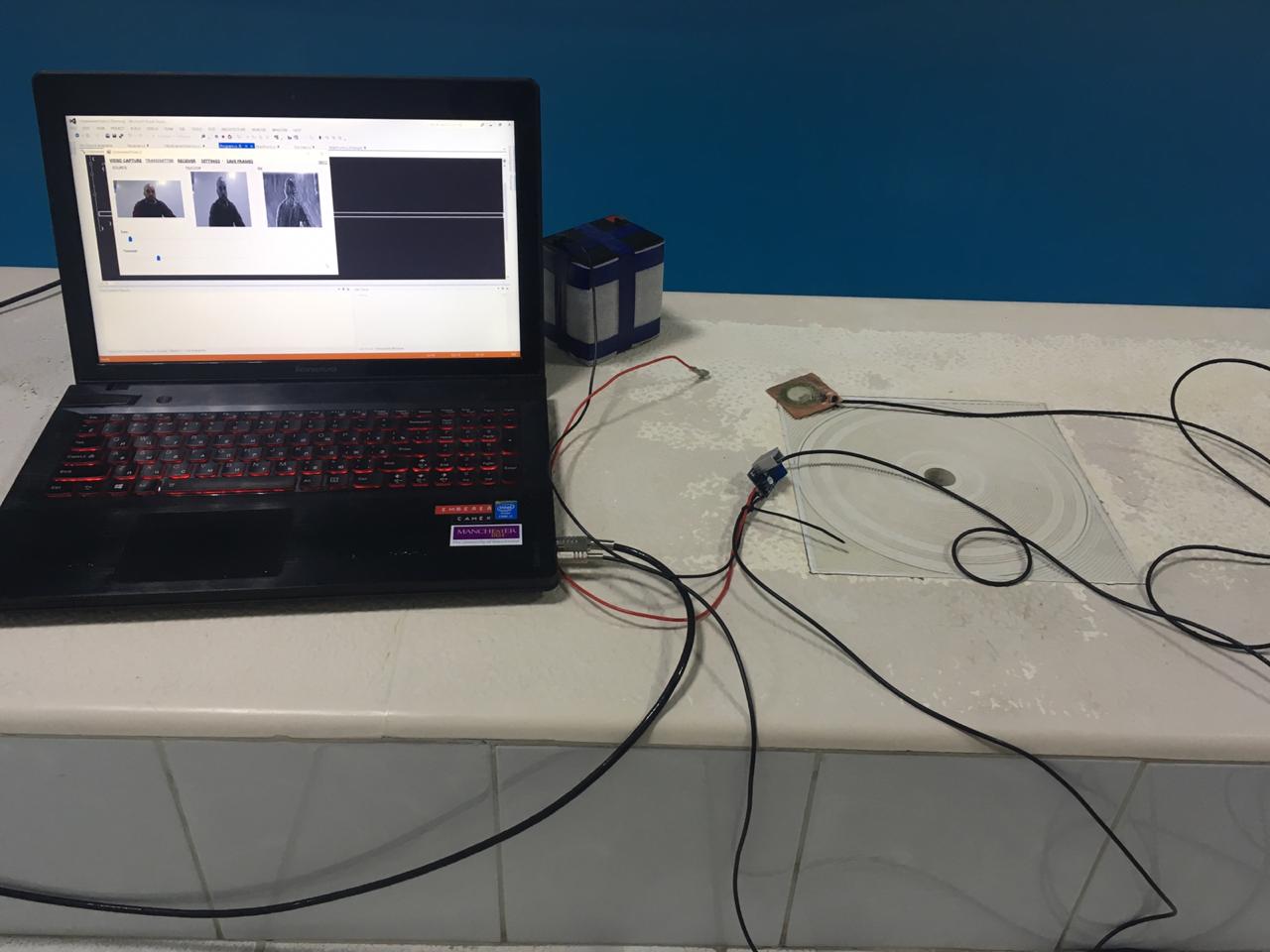
So, to summarize, draw up a list of what we need:
- a pair of sonar antennas from pie pickers
- a preamplifier manufactured by LUT-ohm
- the source code of the project in C #
- a pair of lead batteries for 12 volts
- an amplifier on TDA, I took one for only 50 rubles on Ali
Bit of theory
Recall that our sonar modem was based on a simple tone detector, whose frequency is 4 times less than the sampling frequency. Briefly recall how it works.

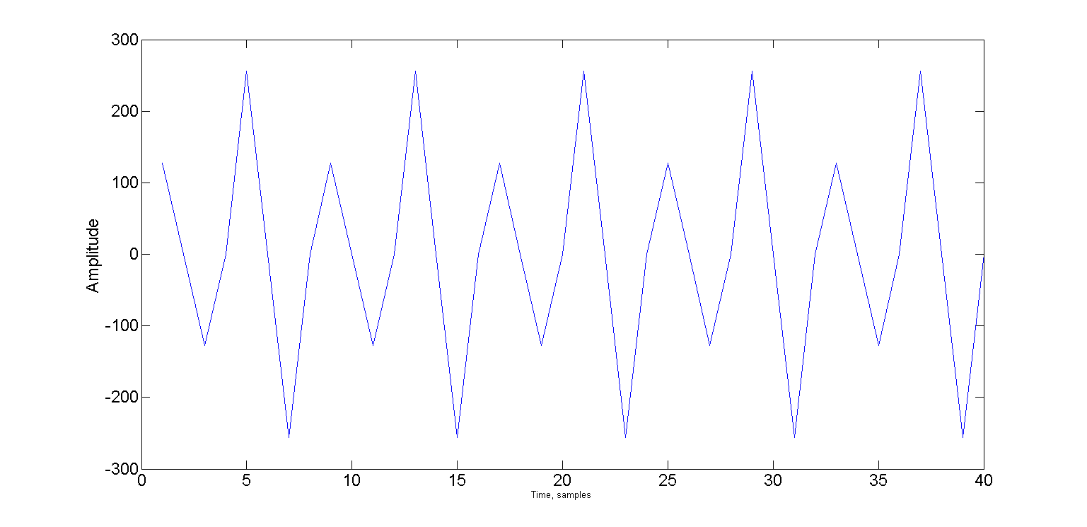
The picture shows two oscillations shifted relative to each other on Pi / 2 - that is, the sine and cosine phases. And if the frequency is exactly four times less than the sampling frequency, then only 4 samples fall on the period.
An attentive habuchitel certainly noticed that both signals are shifted to Pi / 4. With such a shift, the signal takes only two values: √2 / 2 and -√2 / 2.
And specific values are not even important, it is important that you can use only the signs: "+" and "-".
Now we can represent the sine phase as a sequence of signs "+" "+" "-" "-", and the cosine phase as "+" "-" "-" "+".
Under the spoiler, repeat the detector:
Let the input signal be in the sn buffer, we have two ring averaging buffers for the sine and cosine phases - bs and bc of size N. They have common head and tail pointers - bH and bT. At the initial moment of time, bH = N-1, bT = 0. The averaging cycle counter is C = 0.
We take 4 samples from the input buffer and add them according to the sequences of signs. After each processed four samples, we check the counter of averaging cycles and if it has exceeded N, then we calculate the carrier amplitude cA:
We take 4 samples from the input buffer and add them according to the sequences of signs. After each processed four samples, we check the counter of averaging cycles and if it has exceeded N, then we calculate the carrier amplitude cA:
a = sn(i)

bs(bH) = a

bc(bH) = a

s1 = s1 + a - bs(bT)

s2 = s2 + a - bc(bT)

bH = (bH + 1) % N

bT = (bT + 1) % N


a = sn(i+1)

bs(bH) = a

bc(bH) = -a

s1 = s1 + a - bs(bT)

s2 = s2 - a - bc(bT)

bH = (bH + 1) % N

bT = (bT + 1) % N


a = sn(i+2)

bs(bH) = -a

bc(bH) = -a

s1 = s1 - a - bs(bT)

s2 = s2 - a - bc(bT)

bH = (bH + 1) % N

bT = (bT + 1) % N


a = sn(i+3)

bs(bH) = -a

bc(bH) = a

s1 = s1 - a - bs(bT)

s2 = s2 + a - bc(bT)

bH = (bH + 1) % N

bT = (bT + 1) % N
if ++cycle >= N

 cA = sqrt(s1 * s1 + s2 * s2)

 cycle = 0

end
We take this method as a basis; it will be responsible for “synchronization”.
Now let's see how the image is encoded. I suggest using amplitude manipulation . Manipulation is when a signal is divided into equal segments called chips or symbols, and some variable parameter (in our case, the amplitude) is stored along the length of the chip.
If, for example, we can vary the amplitude in the range from 0 to 32767 (16-bit samples), and we need to transfer 255 values of the brightness of the pixels, then per unit of change in the brightness of the pixel, the amplitude of the chip will change to 32768/255 = 128.
Another important parameter is the length of the chip, we start with one carrier period - four samples in our case.
So the picture will be transmitted pixel by pixel, each pixel lasts 4 samples, and the amplitude for this period will be b [x, y] * 128, where b [x, y] is the brightness value of the pixel with x and y coordinates in the image b.
Let's estimate what the transmission speed will be.
In the example, I used a frame size of 120x120 pixels. This means that to transfer one frame, we need
120x420x4 = 57600 samples.
If the sampling frequency is 96 kHz, then transferring one frame will take time:
57600/96000 = 0.6 seconds
Obviously, we need some kind of pause, a certain guard interval, so that the detector can determine the beginning of the next frame. For humane reasons, suppose that 0.1 seconds is enough for us, during which all the echoes die out (actually not). Then, in the end, the transfer rate will be:
1 / (0.6 + 0.1) = 1.428 frames per second.
It is very easy to make a mistake here and try to calculate the speed in bits per second. Look, what an incredible transmission speed it turns out:
120 * 120 * 8 / 1.428 = 80 627 bps
But what happens if I have not 8-bit pixels, but 16-bit ones?
120 * 120 * 16 / 1.428 = 161344 bps The
catch here is that, again, this transmission method cannot be called digital, and the concept of bit rate is not entirely valid for it.
Try to calculate the bit rate for an analog television signal. And for the detector receiver? :)
So, for example, a piece of a signal will look like that conveys the brightness of 10 pixels, the values of which change alternately: 1 2 1 2 1 2 1 2 1 2
Now, let's see how this works in the example. The Encode and Decode methods live in the Encoder class and are responsible for modulating and demodulating the image:
public double[] Encode(Bitmap source, double carrier, int pSize, int interframePauseMs)
        {
            Bitmap frame;
            if (source.PixelFormat != System.Drawing.Imaging.PixelFormat.Format8bppIndexed)
                frame = Grayscale.CommonAlgorithms.RMY.Apply(source);
            else
                frame = source;
            if (!frame.Size.Equals(frameSize))
                frame = resizer.Apply(frame);
            int cols = frameSize.Width;
            int rows = frameSize.Height;
            int col = 0;
            int row = 0;
            double delta = Math.PI * 2 * carrier / sampleRate;
            double alpha = 0;
            double phase = 0;
            double pxAmplitude = 0;
            double chipLimit = Math.PI * 2 * chipSize;
            double pLimit = Math.PI * 2;
            List samples = new List();
            bool isFinished = false;
            for (int i = 0; i < pSize; i++)
            {
                alpha = Math.Sin(phase);
                phase += delta;
                if (phase >= pLimit)
                {
                    phase -= pLimit;
                }
                samples.Add(alpha * short.MaxValue);
            }
            while (!isFinished)
            {
                alpha = Math.Sin(phase);
                phase += delta;
                if (phase >= chipLimit)
                {
                    phase -= chipLimit;
                    pxAmplitude = (((double)frame.GetPixel(col, row).R) / 255.0) * short.MaxValue;
                    if (++col >= cols)
                    {
                        if (++row >= rows)
                            isFinished = true;
                        else
                            col = 0;
                    }
                }
                samples.Add(alpha * pxAmplitude);
            }
            if (interframePauseMs > 0)
            {
                samples.AddRange(new double[(int)((((double)interframePauseMs) / 1000.0) * (double)sampleRate)]);
            }
            return samples.ToArray();
        }
It can be seen from the code that before modulating the image, a sync prefix consisting of a pure tone (pSize samples) is added to the output signal - this is necessary so that synchronization on the receiving side could occur before the image itself
The Decode method is as follows:
public Bitmap Decode(double[] samples, double carrier, int pSize)
        {
            int cols = frameSize.Width;
            int rows = frameSize.Height;
            int col = 0;
            int row = 0;
            Bitmap result = new Bitmap(cols, rows);
            double delta = Math.PI * 2 * carrier / sampleRate;
            double alpha = 0;
            double phase = 0;
            double chipLimit = Math.PI * 2 * chipSize;
            double chipAmplitude = 0;
            double maxAmplitude = WaveUtils.GetMaxAmplitude(samples);
            double pxMax = -maxAmplitude;
            double pxMin = maxAmplitude;
            double smp;
            for (int i = pSize; (i < samples.Length) && (row < rows); i++)
            {
                alpha = Math.Sin(phase);
                phase += delta;
                if (phase >= chipLimit)
                {
                    phase -= chipLimit;
                    chipAmplitude = (Math.Max(Math.Abs(pxMax), Math.Abs(pxMin)) / maxAmplitude);
                    pxMin = maxAmplitude;
                    pxMax = -maxAmplitude;
                    var gs = Convert.ToByte(chipAmplitude * 255);
                    result.SetPixel(col, row, Color.FromArgb(255, gs, gs, gs));
                    if (++col >= cols)
                    {
                        col = 0;
                        row++;
                    }
                }
                else
                {
                    smp = samples[i] * alpha;
                    if (smp > pxMax)
                        pxMax = smp;
                    if (smp < pxMin)
                        pxMin = smp;
                }
            }
            return result;
        }
It can be seen that both methods are not tied to any particular frequency and can be used with another detector.
The signal search itself (detection, synchronization) also takes place as in our simplest hydroacoustic modem , with the only difference being that I put it in a separate class FsBy4CarrierDetector for a change.
All uncomplicated magic happens in the bool ProcessSample method (short a)
public bool ProcessSample(short a)
        {
            bool result = false;
            if (smpCount == 0)
            {
                ring1[ringHead] = a;
                ring2[ringHead] = a;
                s1 += a - ring1[ringTail];
                s2 += a - ring2[ringTail];
            }
            else if (smpCount == 1)
            {
                ring1[ringHead] = a;
                ring2[ringHead] = -a;
                s1 += a - ring1[ringTail];
                s2 += - a - ring2[ringTail];
            }
            else if (smpCount == 2)
            {
                ring1[ringHead] = -a;
                ring2[ringHead] = -a;
                s1 += -a - ring1[ringTail];
                s2 += -a - ring2[ringTail];
            }
            else if (smpCount == 3)
            {
                ring1[ringHead] = -a;
                ring2[ringHead] = a;
                s1 += -a - ring1[ringTail];
                s2 += a - ring2[ringTail];
            }
            ringHead = (ringHead + 1) % ringSize;
            ringTail = (ringTail + 1) % ringSize;
            if (++smpCount >= 4)
            {
                smpCount = 0;
                if (++cycle >= ringSize)
                {
                    s = Math.Sqrt(s1 * s1 + s2 * s2) / ringSize;
                    cycle = 0;
                    result = (s - sPrev) >= Threshold;
                    sPrev = s;
                }
            }
            return result;
        }
It is called on every incoming sample and returns true in case of carrier detection.
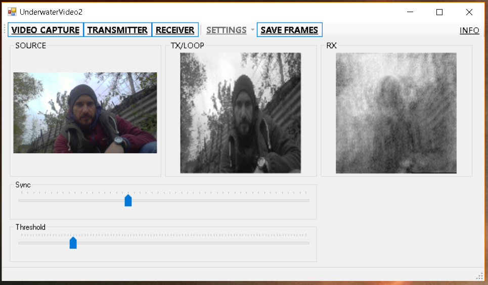
Since the detector is far from perfect, and can easily be synchronized in the middle of the line, I added a special slider, moving which you can achieve more accurate synchronization.
Now, after we have briefly examined how this all works, let's move on to the most delicious part: what can be obtained from all this.
A bit of practice
First, let’s check how everything works without a sonar channel - simply by attaching the receiving and transmitting antennas to each other.
First, the picture is larger (240x120), so that at least something can be made out:

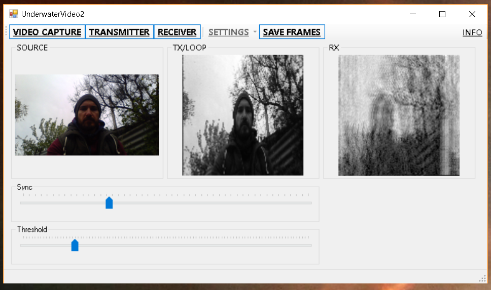
And then quickly, so that there is
It seems to be not bad? But we do not rush to conclusions, and we go to the swimming pool:
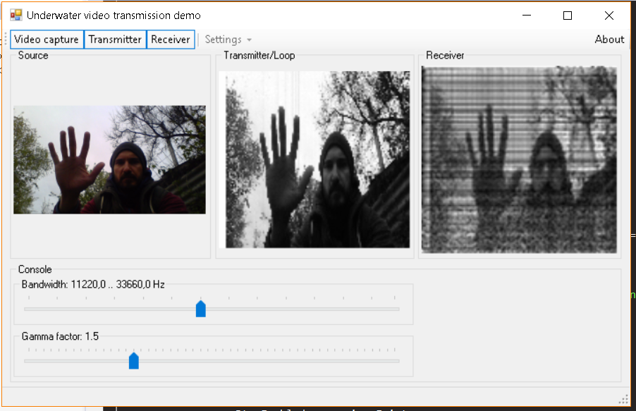
And here, as I promised in the title, we will see with our own eyes the echo:
How
And everything is very simple - the echo in essence is the delayed copies of the original signal, famously interfering with it at the receiving point, folding in a different phase and giving such a picture. Since we transfer the picture, in the end we get many many pictures superimposed on each other with different amplitudes. All this ultimately leads to blurring and reproduction.
Looking back, let's check everything on the model large picture. I took a random photo: I
modulated it, then added an echo and a bit of noise, then decoded it, and yes - the result resembles what we got in the pool:
In principle, you can perform deconvolution and subtract reflections, but
By the way, the previous method in the pool works a little better, but also badly - on broadband signals, multipath and reverberation lead to frequency selective fading, which in the picture (read on the spectrum) looks like black and white stripes - where the signal is in antiphase, and where it took shape in the phase (in fact, there are still a lot of intermediate options):
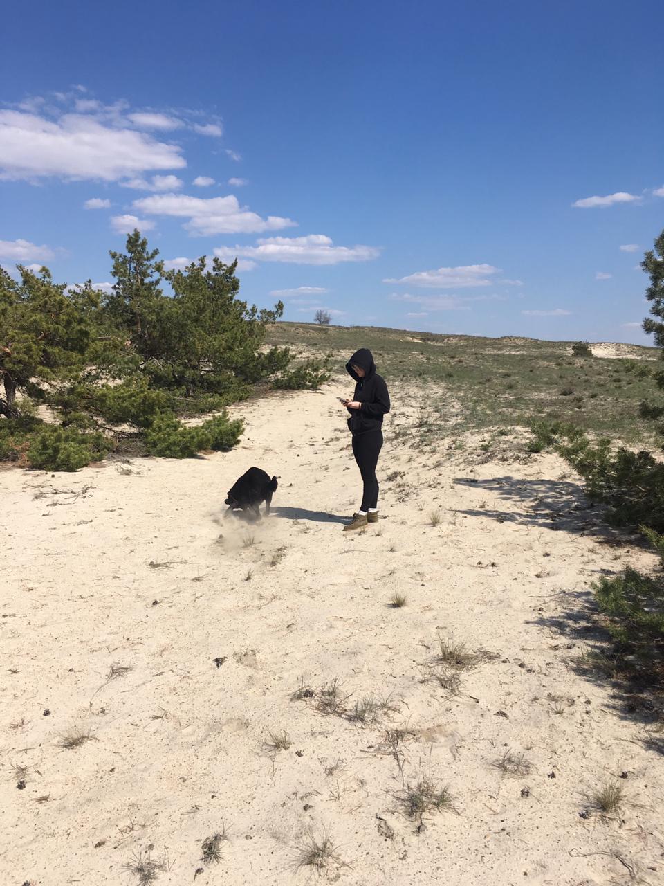
In April, we seized the moment and went to the pond with a mockup and indulged there:
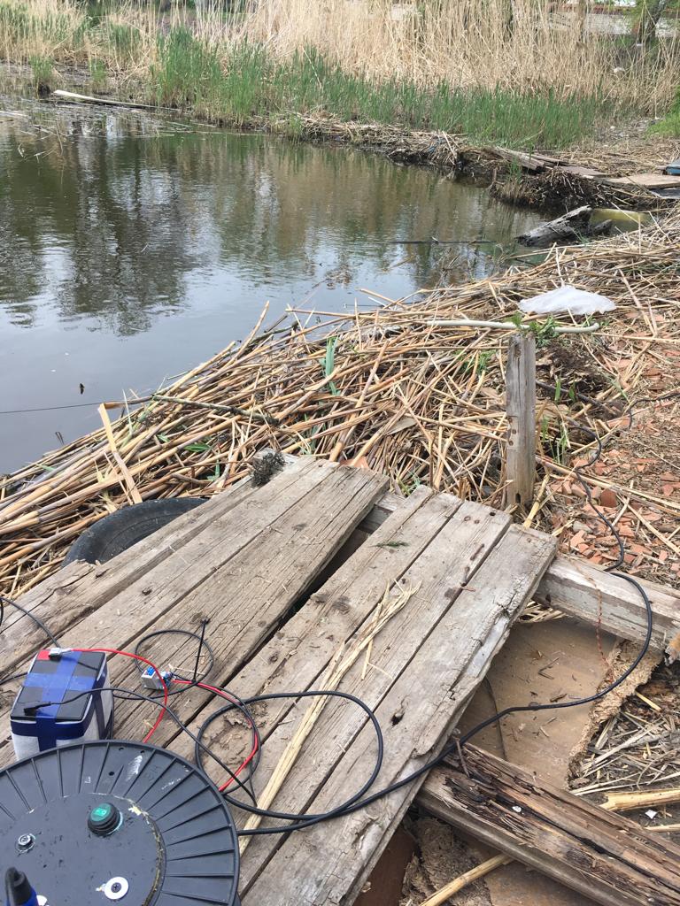
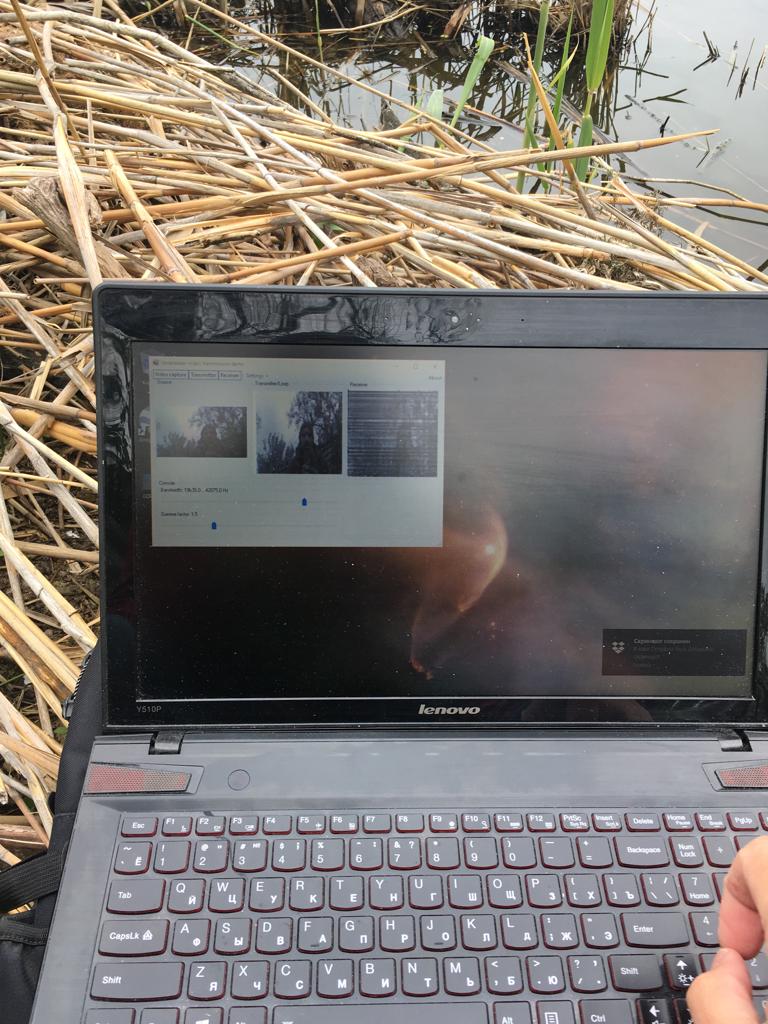
The result is not much different from the results obtained in the pool:
And immediately for comparison the fore uschy method:
Here is collected from the stored frames gif-animation, Method 1:
And the method 2, which we discuss in this article:
Finally
As promised, we showed how the echo and reverb look literally, spent time with benefit and did something with our hands.
In this form, of course, the method is not applicable in practice, but working with it will be very useful for beginners.
In general, we checked in a shallow pond, where the conditions are very unfavorable, and it would be cool if someone would repeat our experiments in other reservoirs and would certainly tell about their results.
If the reader just wants to try (even in the air with a microphone and speakers), then here are the links to releases:
Method-1
Method-2 (from this article)