Seven-segment decoder using both direct and inverse outputs of a BCD counter
- Transfer
- Tutorial

The “binary clock” managed to get into fashion and get out of it, and again the conversion of the binary decimal code to a positional or seven-segment code that is more convenient for human reading has become relevant. The author chose the second.
The solution lying on the surface is to convert the code into a positional, then a diode matrix into a seven-segment one. This is sometimes done, but there is another option: a decoder consisting of four inverters, which, in addition to direct signals from the counter outputs, allows receiving inverse and signal shapers for each of the indicator segments:

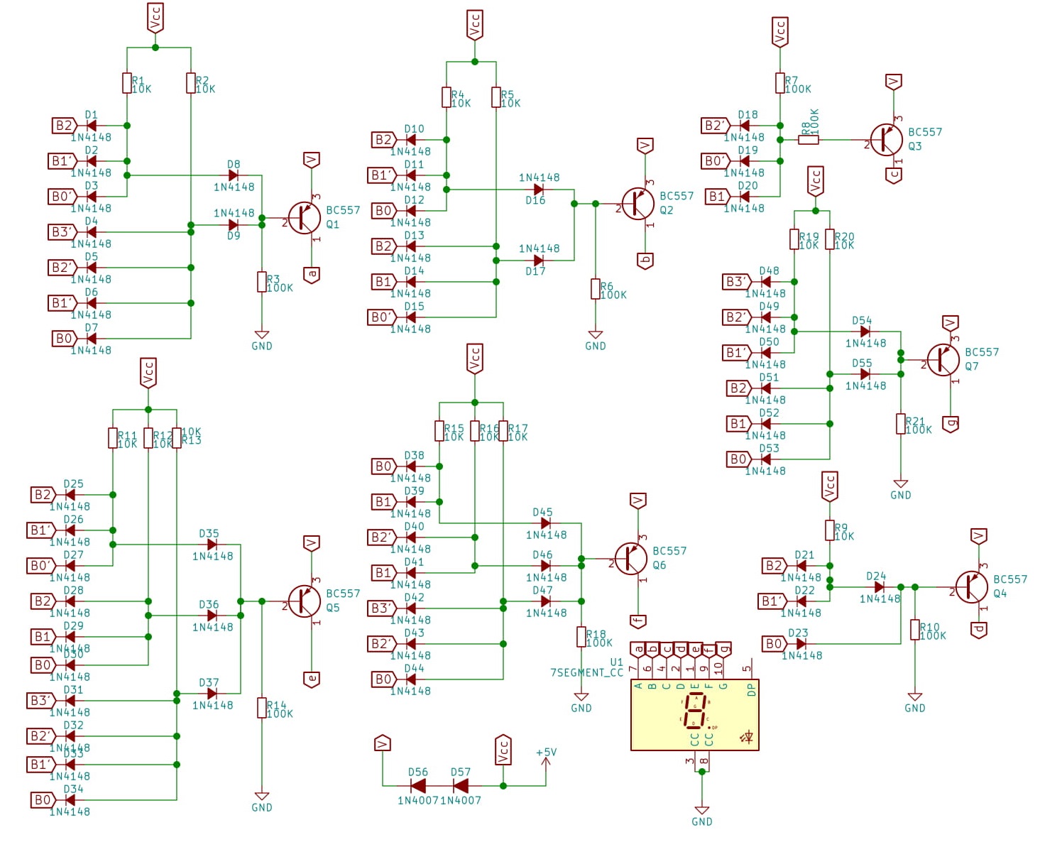
But here the decoder is designed to connect to this counter, which already has direct and inverse outputs, which makes additional inverters in the decoder unnecessary. The outputs Q0 - Q3 and Q0 '- Q3' of the counter are connected, respectively, to the inputs B0 - B3 and B0 '- B3' of the decoder. The signal conditioner for each of the segments consists of:
- one or more diode "And"
- diode "OR" (if required)
- a transistor switch that controls the segment LED (the indicator must be with a common cathode).
Thanks to the chain of two diodes shown below, the indicator voltage is approximately one volt lower than the logic voltage. Resistors in the base and load circuits must be added
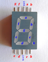
to the keys . The author used an indicator with such a pinout: In this form, the decoder can display only 0–9 symbols on the indicator. But the counter used with it can be switched by a switch from binary-decimal to binary mode. By adding additional diodes to the decoder, you can also display the characters A - F. Or a hyphen, L, C, G, E and a space if you prefer them.