CAN Driving
Introduction
The StarLine unmanned vehicle based on the Lexus RX 450h platform is a research project launched in 2018. The project is open to ambitious professionals from the Open Source Community . We offer everyone to participate in the development process at the code level, to test their algorithms on a real car equipped with expensive equipment. To control the car, it was decided to use Apollo, an open framework. For Apollo to work, we needed to connect a set of modules. These modules help the program receive information about the car and control it according to the specified algorithms.
These modules include:
- module for positioning a car in space using GPS coordinates;
- module for steering, acceleration and braking of a car;
- module of the state of car systems: speed, acceleration, steering wheel position, depressing the pedals, etc .;
- module for obtaining information about the environment of the car. Ultrasonic sensors, cameras, radars and lidars can handle this.
First of all, our team was faced with the task of learning to control the steering wheel, acceleration and braking of the car. And also receive information about the state of car systems. For this, a lot of work was done to study the Lexus CAN bus.
Theoretical part
What is a CAN bus?
In modern cars, electronic systems took control of all systems (Fig. 1.). Electronic components are specialized computers, each of which has all the necessary interfaces for integration with a car. Using digital communication interfaces, the units are networked to exchange information with each other. The most common digital interfaces in cars are CAN, LIN, FLEXRay. Of these, CAN is most widely used.
CAN (Controller Area Network) bus is the industry standard network. In 1986, this standard was developed by Bosch. And the first car with a CAN bus was the Mercedes-Benz W140, released in 1991. The standard was developed to allow devices to communicate with each other without a host. Information is exchanged using special messages, which consist of ID fields, message length and data. Each block has its own set of IDs. In this case, a message with a lower ID has priority on the bus. The data field can carry information, for example, on the status of systems and sensors, commands for controlling mechanisms, etc.
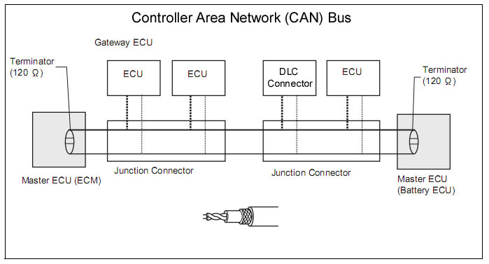
Fig. 1. Vehicle CAN bus.
At the physical level, the bus is a twisted pair of copper conductors. The signal is transmitted differential, due to which high noise immunity is achieved.
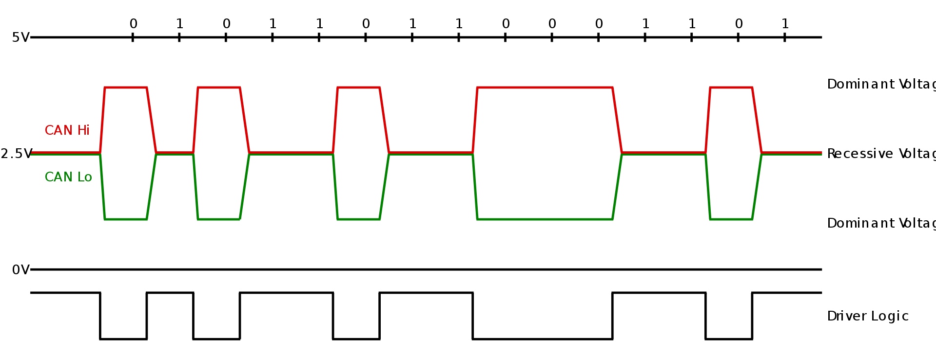
Fig. 2. Physical representation of the signal in the CAN bus
Using the CAN bus, you can obtain information about the status of various sensors and vehicle systems. Also via CAN, you can control the components of the car. It is these opportunities that we use for our project.
We chose Lexus RX because we knew that we could manage all the necessary nodes via CAN. Since the most difficult thing when researching a car is closed protocols. Therefore, one of the reasons for choosing this particular car model was the presence of a description of the CAN bus protocol part in the Openpilot opensource project.
Properly driving a car means understanding how the mechanical parts of a car’s systems work. We needed to have a good understanding of how to work with an electric power amplifier or control the deceleration of a car. Indeed, for example, when the wheels are turned, they create resistance to the steering, which introduces restrictions on the steering when turning. Some systems cannot be used without entering the car in special operating modes. We had to study these and other details in the process.
Electric power steering
Electric power steering EPS (Electric Power Steering) is a system designed to reduce steering force when turning (Fig. 3). The prefix "electro" talks about the type of system - electric. Steering the steering wheel with this system becomes comfortable, the driver turns the steering wheel in the right direction, and the electric motor helps to turn it to the desired angle.
An electric power amplifier is installed on the steering shaft of a car, the parts of which are interconnected by a torsion shaft. A torque sensor (Torque Sensor) is mounted on the torsion shaft. When the steering wheel rotates, the torsion shaft twists, which is recorded by the torque sensor. The data received from the torque sensor, speed sensors and crankshaft revolutions are fed to the ECU electronic control unit. And the ECU, in turn, already calculates the necessary compensation force and gives a command to the electric motor of the amplifier.
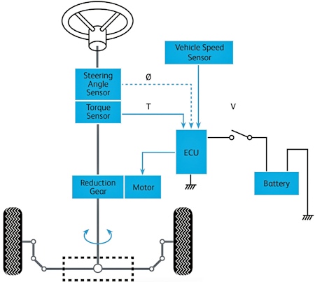
Fig. 3. Schematic diagram of the electric power steering system
Video: The LKA system steers a car using the EPS system.
Electronic gas pedal
The throttle is a mechanism for adjusting the amount of fuel mixture that will fall into the engine. The more mixture gets, the faster the car goes.
The electronic gas pedal is a system that involves the operation of several electronic components. The signal about the position of the pedal, when it is pressed, enters the engine control unit ECM (Engine Control Module). The ECM, based on this signal, calculates the required amount of fuel that must be supplied to the engine. Depending on the amount of fuel needed, the ECM adjusts the throttle opening angle.
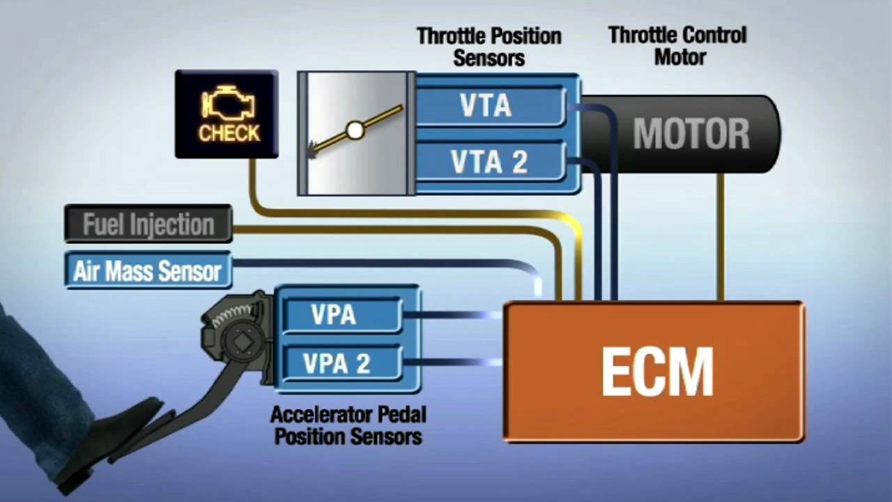
Fig. 4. The electronic gas pedal system.
Video: The electronic gas pedal is used to operate the cruise control.
Electronic driver assistance systems
We bought a car that is equipped with a variety of digital units and driver assistance systems (ADAS). In our project we use LKA, ACC and PCS.
LKA (Lane Keep Assist) is a strip retention system that consists of a front camera and a computing unit. LKA keeps the car in the lane when the driver, for example, is distracted. Algorithms in the computing unit receive data from the camera and based on them make a decision about the condition of the car on the road. The system is able to understand that the car is moving uncontrollably towards the right or left lane. In such cases, a beep sounds to attract the attention of the driver. When crossing the lane, the system itself will adjust the angle of rotation of the wheels so that the car remains in the lane. The system should only intervene if it realizes that the maneuver between the lanes was not caused by the driver.
ACC (Adaptive Cruise Control) - an adaptive cruise control system that allows you to set the desired speed. The car itself accelerates and slows down to maintain the desired speed, while the driver can remove his foot from the gas and brake pedals. This mode is convenient to use when driving on highways and freeways. Adaptive cruise control is able to see obstacles in front of the car and slow down to avoid collision with them. If another vehicle at a lower speed drives ahead, ACC will slow down and follow. When a static object is detected, the ACC will slow down until it stops. To detect objects in front of the car, such a system uses a radar with a millimeter wavelength range. Typically, such radars operate at a frequency of 24-72 GHz and are able to confidently see objects at a distance of 300 meters. The radar is usually installed behind the front badge on the grille.
PCS (Pre-Collision System) - collision avoidance system. The system is designed to prevent a collision with a car that is moving in front. When a collision is inevitable, the system minimizes collision damage. It also uses radar to estimate the distance to the object and a front camera for its recognition. The PCS front predicts the probability of a collision based on the vehicle’s speed, distance to the object and its speed. Typically, a system has two stages of operation. The first stage - the system sounds and displays on the dashboard notifies the driver of the danger. The second stage - emergency braking is activated using the ABS system, and seat belt pretensioners are activated.
Practical part
Steering
The first thing our team wanted to do was learn to steer. The steering wheel in a car can be controlled by two systems: IPAS parking assistant (Intelligent Park Assist) and LKA.
IPAS allows you to set the steering angle in degrees directly. Since our car does not have this system, it is impossible to check and master the steering in this way.
Therefore, we studied the electrical circuits of the car and realized which CAN buses could be useful. We connected a CAN bus analyzer. The log contains a file of message records in the bus in chronological sequence. Our task was to find EPS power steering teams (Electric Power Steering). We took the steering wheel log from side to side, in the log we could find the readings of the angle of rotation and the speed of rotation of the steering wheel. Below is an example of changing data in the CAN bus. The data of interest to us is highlighted with a marker.

Turn the steering wheel 360 degrees to the left

Turn the steering wheel right 270 degrees
In the next step, we examined the lane retention system. To do this, we went to a quiet street and recorded the exchange logs between the lane holding unit and the DSU (Driving Support ECU). Using the CAN bus analyzer, we were able to compute messages from the LKA system. Figure 6 shows the EPS control command.
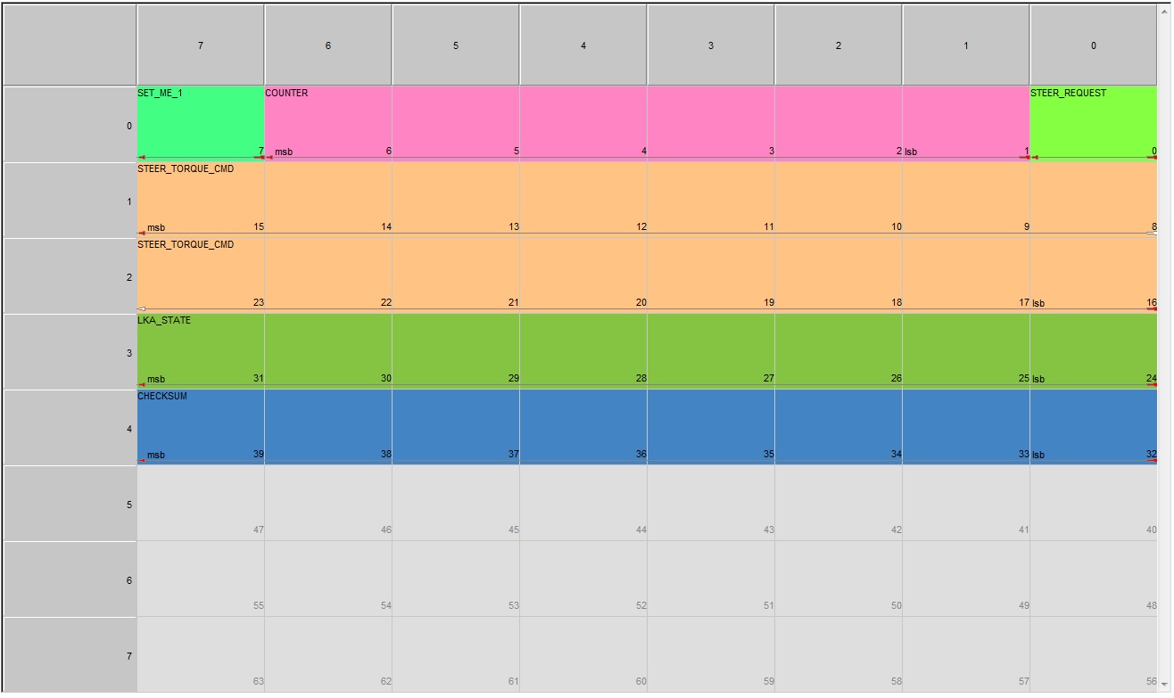
Fig. 5. Steering command using the LKA system The LKA
controls the steering wheel by setting the torque value on the shaft (STEER_TORQUE_CMD) of the steering wheel. The command is accepted by the EPS module. Each message contains a counter value (COUNTER) in the header, which is incremented with each sending. The LKA_STATE field contains LKA status information. To capture control, you must set the STEER_REQUEST bit.
Messages that are responsible for the operation of important auto systems are protected by a checksum (CHECKSUM) to minimize the risks of false alarms. The car will ignore such a command if the message contains an incorrect checksum or counter value. This is a manufacturer-built protection against third-party system interference and interference in the communication line.
The graph (Fig. 6.) shows the LKA operation diagram. Torque Sensor - value from the torque sensor on the torsion shaft. Torque Cmd is a team from LKA for steering. The picture shows how the LKA is steered to hold the car in the lane. When crossing through zero, the direction of rotation of the steering wheel changes. Those. a negative signal indicates a turn to the right, a positive value to the left. Keeping the command at zero indicates a lack of control by the LKA. With the intervention of the driver, the system ceases to issue control. LKA detects driver intervention with a second torque sensor on the shaft from the steering wheel side.
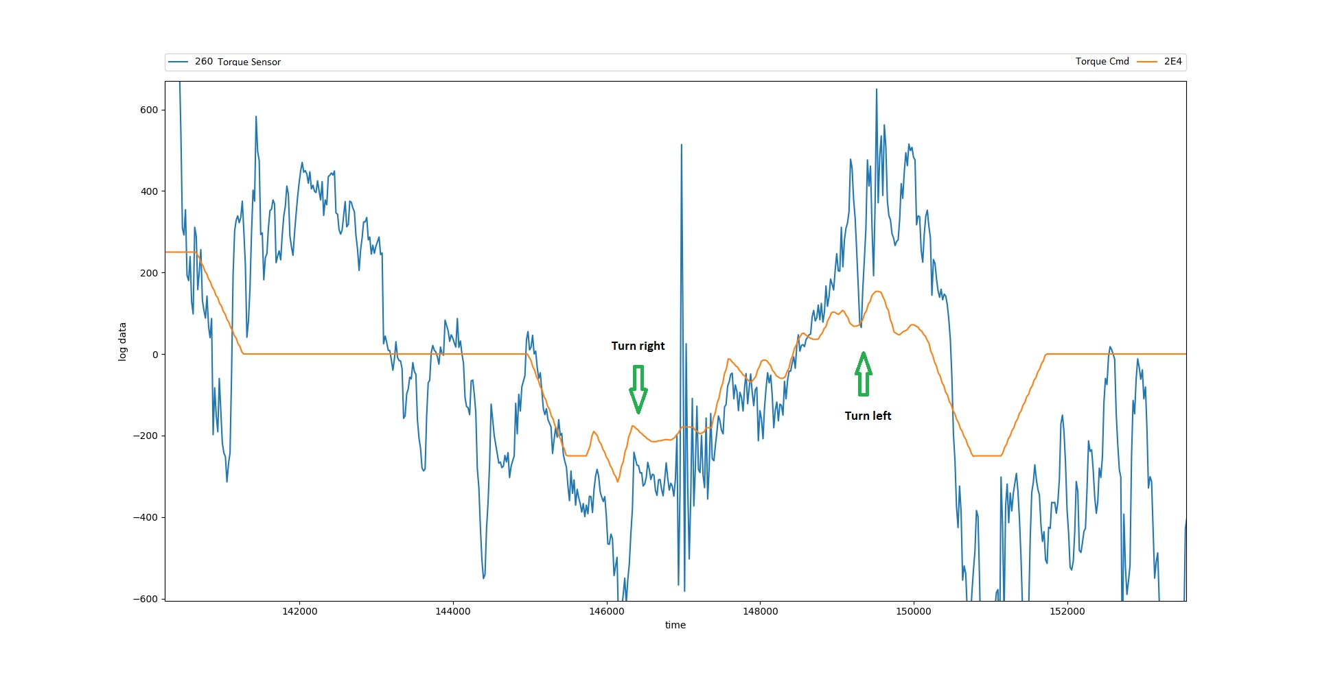
Fig. 6. Schedule of the LKA system
We had to check the work of the steering team. Using the StarLine Sigma 10 module, we prepared the firmware for control testing. StarLine Sigma 10 should issue commands to the steering wheel to turn the steering wheel left or right. At that time, we did not have a graphical interface for controlling the module, so we had to use the standard means of the car. We found the status of the position of the cruise control lever in the CAN bus and programmed the module in such a way that the upper position of the lever led to the steering wheel turning to the right, the lower position to turning to the left (Fig. 7).
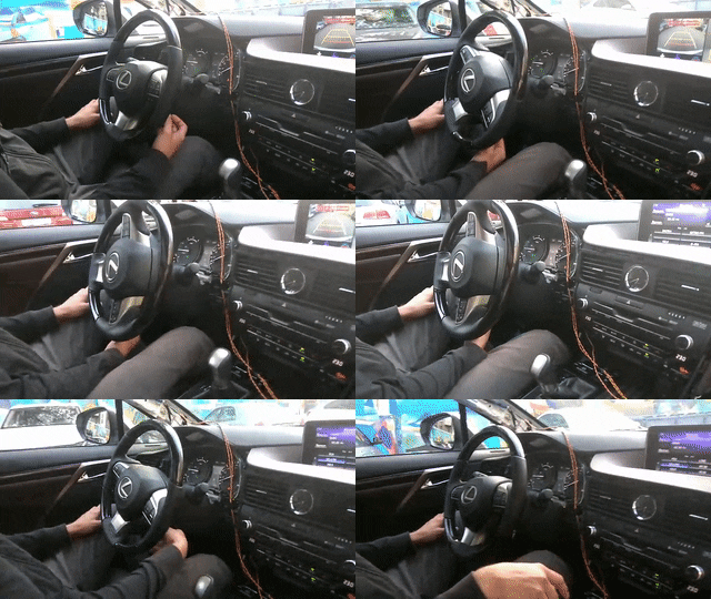
Fig. 7. The first attempts to steer
The video shows that the control is carried out in short sections. This occurs for several reasons.
The first reason is the lack of feedback. If the discrepancy between the Torque Cmd signal and the Torque Sensor exceeds a certain Δ value, the system automatically stops accepting commands (Fig. 8). We set the algorithm to adjust the output command (Torque CMD) depending on the value of the torque on the shaft (Torque Sensor).
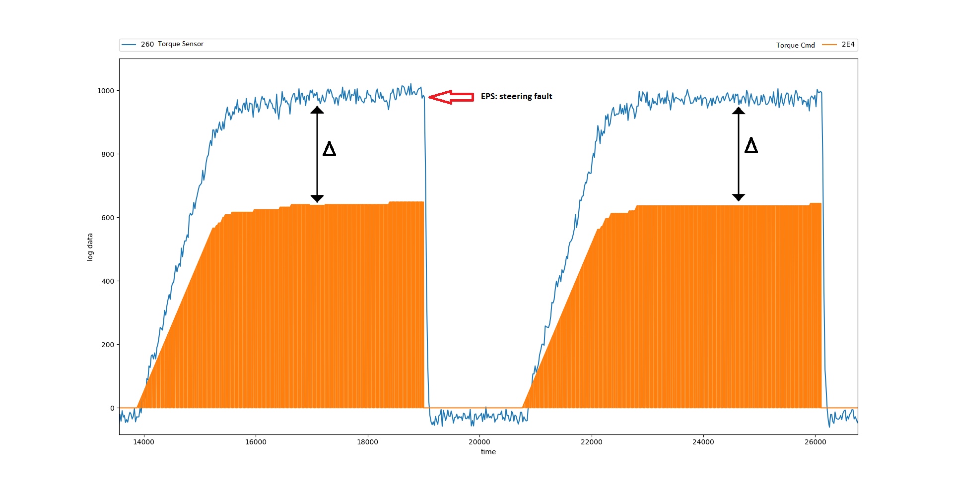
Fig. 8. Signal discrepancy leads to a system error.
The following limitation is associated with the protection system built into EPS. The EPS system does not allow LKA teams to steer over a wide range. Which is quite logical, because when driving on the road, sudden maneuvering is not safe. Thus, when the threshold value of the torque on the shaft is exceeded, the LKA system generates an error and turns off (Fig. 9).
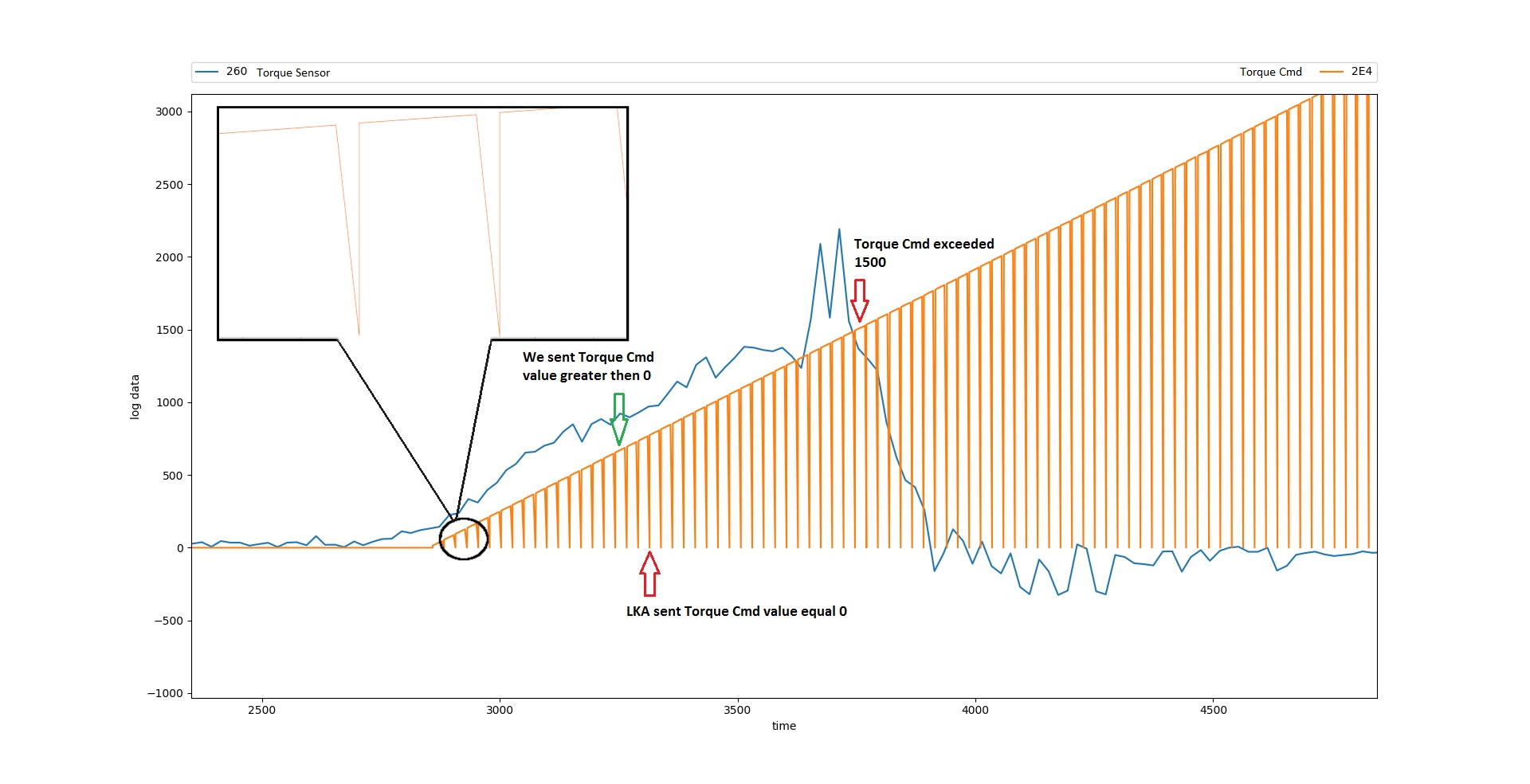
Fig. 9. Exceeding the threshold value of the torque control on the shaft
Regardless of whether the LKA system is activated or not, messages with commands from it are constantly present on the bus. We instruct the EPS module to turn the wheels with a specific force left or right. Meanwhile, LKA interrupts our packages with "empty" messages. After our team with the value of the moment, the standard comes with zero (Fig. 10).
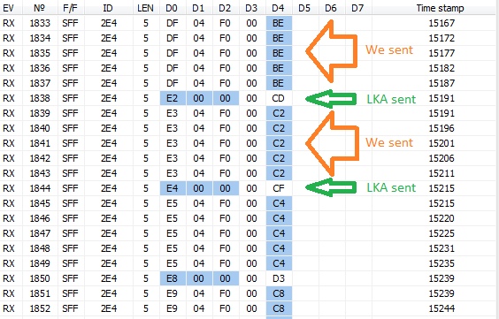
Fig. 10. Regular messages come with zero moment values and interrupt our control.
Then, using the StarLine Sigma 10 module, we were able to filter all traffic from LKA and block messages with ID 2E4 when we needed it. This solved the problem, and we managed to get a smooth steering control (Fig. 11).
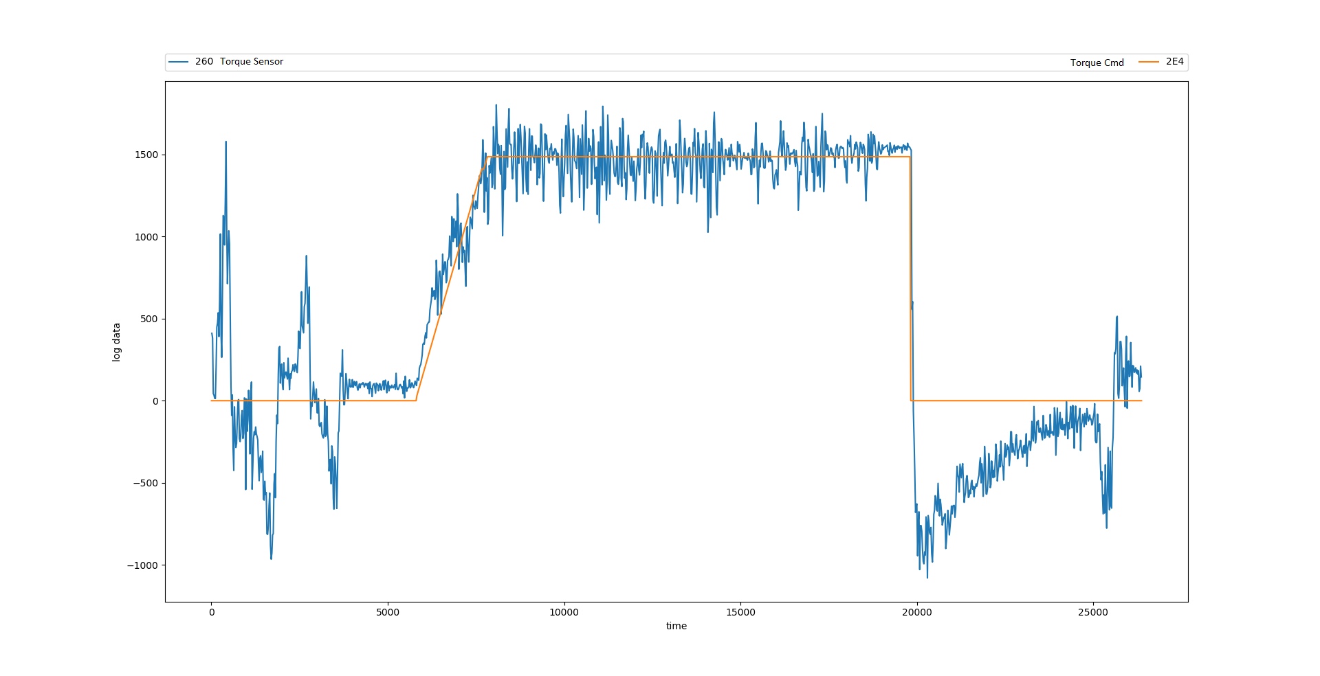
Fig. 11. Smooth steering wheel adjustment without errors
Gas management
The ACC Adaptive Cruise Control system controls acceleration and braking software via the CAN bus. The ECU engine control unit receives DSU commands, if you need to accelerate, it activates the electronic gas pedal. Regenerative braking is used to brake the car. In this case, one command is used for braking and acceleration, only the values differ.
The acceleration or deceleration control command is shown in Figure 12. It consists of the acceleration value ACCEL_CMD, a pair of overhead bits, and a Checksum checksum. For vehicle acceleration, ACCEL_CMD is positive; for deceleration, negative. Acceleration is set in the range from 0 to 3 m / s ^ 2, deceleration is similar, but with a minus sign. To send data to the bus, it is necessary to recalculate the desired acceleration or deceleration with a coefficient of 0.001. For example, to accelerate 1 m / s ^ 2, ACCEL_CMD = 1000 (0x03E8).
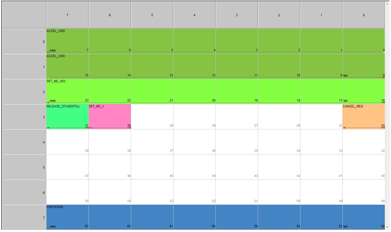
Fig. 12. Vehicle Acceleration / Deceleration Control Team
We removed the logs from the standard ACC system and analyzed the commands. Compared with our description of the teams and started testing.

Fig. 13. ACC adaptive cruise control acceleration / deceleration control log (highlighted by a marker).
There were some difficulties here. We drove on a road with busy traffic to test the acceleration team. The vehicle’s acceleration or deceleration control commands work only when cruise control is activated, it is not enough to activate it with the button. It is necessary to find the car moving in front and turn on the following mode.
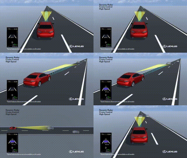
Fig. 14. Activation of the cruise control occurs when there is another vehicle ahead
Using the StarLine Sigma 10 module, we send an acceleration command, and the car starts to pick up speed. At this point, we connected the graphical interface for controlling the StarLine Sigma 10. Module. Now we control the steering wheel, acceleration and braking using the buttons in the application.
The teams worked until they lost the car ahead. The cruise control system was turned off, and therefore the acceleration commands stopped working.
We began to study the possibility of using teams without active cruise control. I had to spend a lot of time analyzing the data in the CAN bus to understand how to create the conditions for the teams to work. We were interested, first of all, which block blocks the execution of ACC commands for acceleration or deceleration. I had to study which IDs come from DSU, LKA, radar and camera, palm off the fake data of various sensors.
The decision came 3 weeks later. By that time, we had an idea of how the blocks of the car interact, carried out a study of message traffic and identified groups of messages sent by each block. Driving Support ECU (DSU) is responsible for the adaptive cruise control ACC. The DSU issues commands to accelerate and decelerate the car, and it is this unit that receives data from the millimeter range radar. The radar tells the DSU at what distance from the machine the object is moving, at what relative speed and determines its horizontal position (to the left, right, or center).
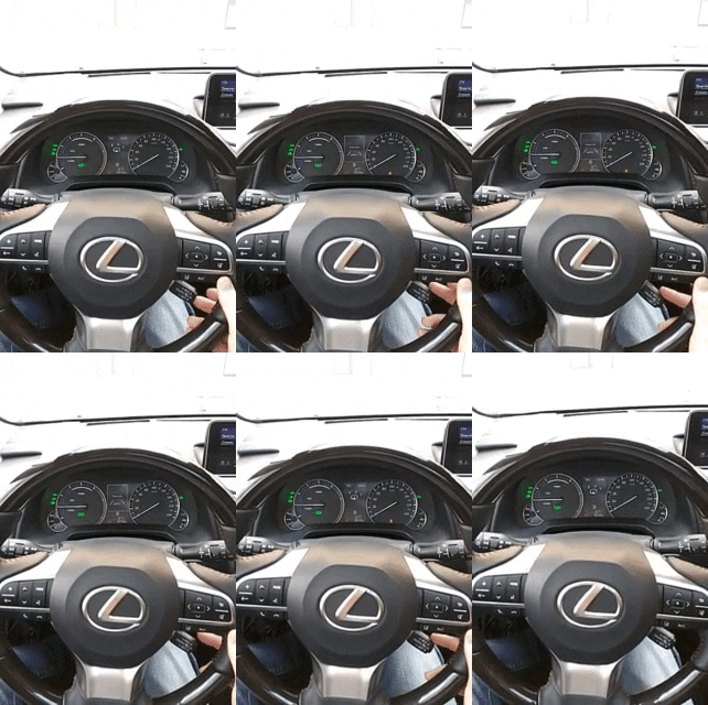
Our idea was to replace the radar data. We removed the log for following the car, pulled out the radar data from it at the moment of following. Now, after turning on the cruise control, we send fake data about the presence of a car in front. It turns out to deceive our car, saying that another car in front moves at a specific distance.
a)
 b)
b) 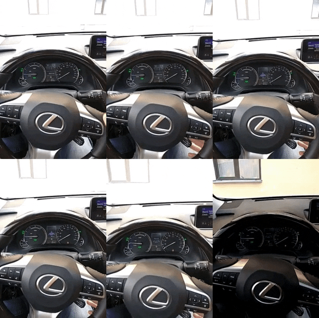
Fig. 15. Cruise activation: a) attempt to activate without replacing radar data; b) activation when replacing data from the radar.
When we start our snag, on the dashboard the presence icon of the vehicle in front is lit. Now we can test our management. We start the acceleration command, and the car starts to accelerate quickly.
As we already learned, the acceleration and deceleration command is one. Therefore, they immediately checked the deceleration. We went at speed with active cruise control, launched a braking command, and the car immediately slowed down.
As a result, now it turns out to accelerate and slow down the car exactly as we needed.
The goal is achieved.
What else do we use
To create a drone, it is necessary to control auxiliary systems: turn signals, brake lights, alarms, horn, etc. All this can also be controlled via the CAN bus.
Hardware and software
To work with the car today we use a set of various equipment:
- The Marathon Bus Analyzer allows you to connect and read data from two buses simultaneously. The analyzer manufacturer’s site has free log analysis software. But we use software written in our company for internal use.
- We use the StarLine Sigma 10 module as a platform for working with digital interfaces. The module supports CAN and LIN interfaces. When researching a car, we write programs in C, sew them into the module and check the operation. From the module, we can make a CAN bus traffic sniffer. The sniffer helps us understand which IDs are coming from the block or block messages from regular systems.
- Diagnostic equipment Toyota / Lexus. With the help of this equipment you can find commands to control car systems: turn signals, brake lights, horn, tidy indication.
Today, active work is underway to develop an unmanned vehicle, in the near future, the implementation of emergency braking before obstacles, their detour and restructuring the car’s route depending on the traffic situation and the driver’s instructions.
The StarLine unmanned vehicle is an open platform for combining the best engineering minds of Russia and the world with the aim of creating advanced unmanned driving technologies that will make our future safe and comfortable.
Gitlab project
