Test drive nanoCAD SPDS Construction site 8. Part 2
- Tutorial
Test drive nanoCAD SPDS Construction site 8
We continue to publish the test drive for nanoCAD SPDS Construction site. In the first part of the test drive, we examined the work with the special tool Project Manager, its main functions and methods of constructing elements of the construction plan. In the second part of the test drive, we will consider the construction of roads and the selection of equipment.

Theme 3. Construction of roads
In this topic, we will consider the construction of roads and their elements using nanoCAD Construction site.
To work, you need the file "\ Topic 3_Construction of Roads \ Task \ Roads.dwg". In the course of performing exercises on this topic, we will launch all the commands from the section of the “Construction Site-Roads” main menu section, therefore, further teams will be written in abbreviation, without indicating this part of the path. To start the exercise, open the Roads.dwg file in nanoCAD Construction Site.
3.1 Main road
Run the Roads command to set parameters and build roads.
In the dialogue, select the type of road "Automobile temporary roads." Pay attention to the belonging of the road to the construction site. Road parameters can be set in the properties and directly on the diagram. Select the width of the road and set 6000 mm.
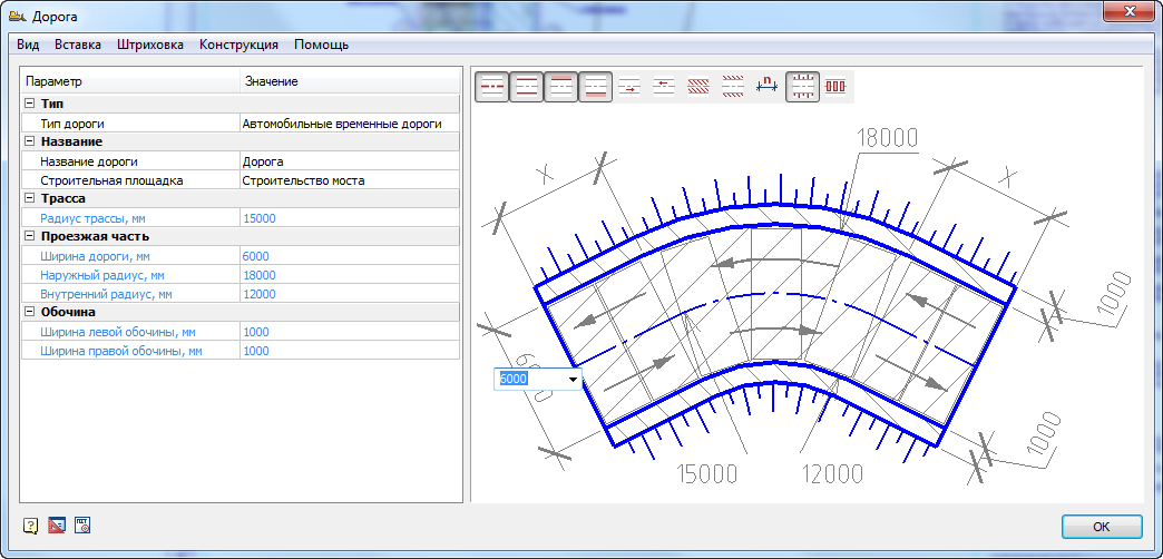
The visibility of road elements can also be configured through the "View" menu or directly in the figure. A single click on a road element displays it in gray and blue. When displayed in blue, it will be shown in the drawing, in gray it will not. Show the slopes, hide the dimensions and hatching, as shown. Other parameters can be left unchanged.
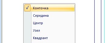
Click "OK" and enable the "Point" binding in nanoCAD, if it was not enabled.
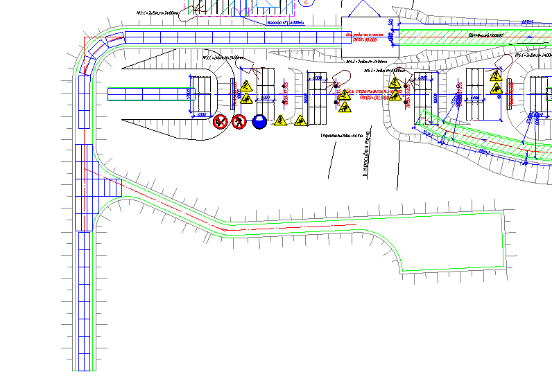
Indicate three points in succession to build the road. The first point is located at the lower end of the axial vertical line on the left side of the drawing. The second point is at the upper end of the center line, as shown.
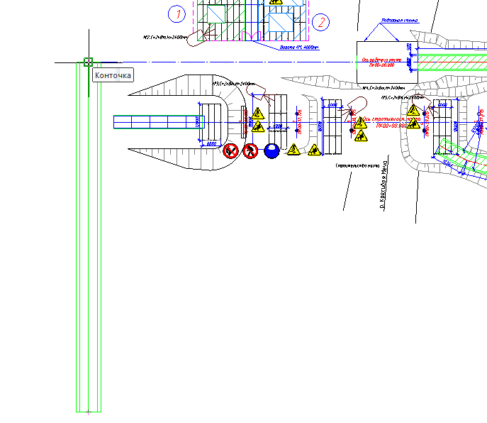
For the last point, enable the Midpoint snap. Indicate the third point by turning right on the other axis, as shown in the following figure. Please note that the turn formed automatically according to the settings of the radii of the roads.
By double-clicking on the road, you can call up the editing dialog and hide / show its various components.
3.2 adjoining road
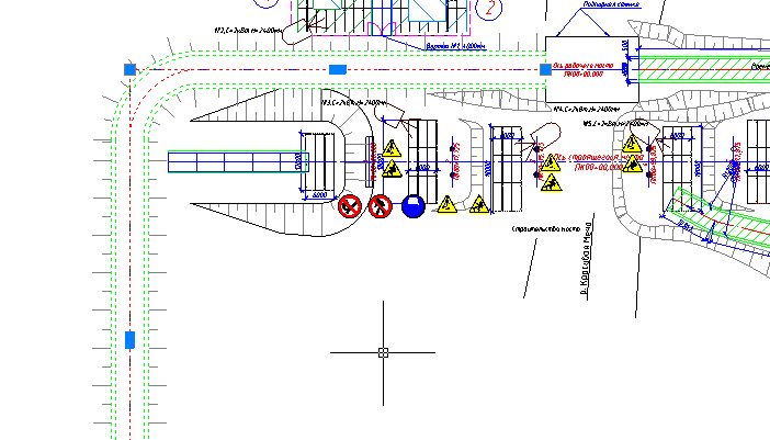
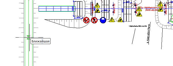
Run the Roads command. Specify the width of the road 3500 mm in the parameters, leave the rest unchanged, as on the main road. Make sure nanoCAD bindings are enabled. Using "Nearest", point to the axis of the main road, as shown in the figure.
Next, build a pair of road segments as shown.
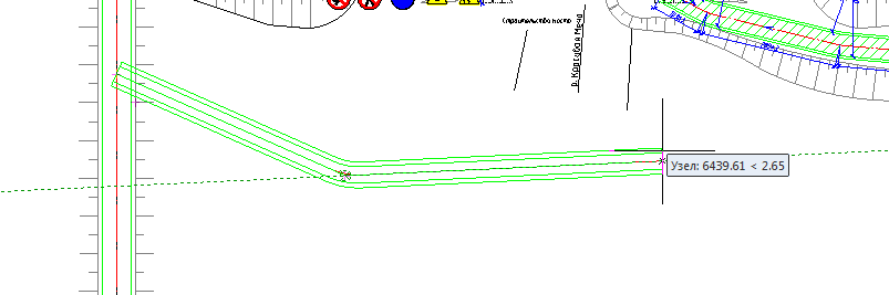
After specifying the last point, press Enter. Please note that the crossroads formed automatically.
3.3 U-Turn
Double-click to enter the adjoining road editing dialog. Go to the menu "Insert - Insert widening / reversal pad."

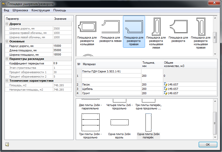
In the dialog that appears, select the site type “Right U-Turn”. Leave all parameters as default, as shown in the figure.
After moving the cursor along the road, position the site as far to the right. It should turn out as shown in the figure.
3.4. Laying road plates on the road
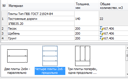
Double-click to enter the main road editing dialog, the width of which is 6000 mm. In the dialog, run the command “Design - Construction of pavement”. In the “Pavement Design” window, from the drop-down list of materials, select the “Plates Type PBB GOST 21924-84” plates and indicate the brand of plates “1PBB35.20”. In the layout options, select the icon "Two plates 2x6m in parallel." Other parameters can be left unchanged. Also note that the geometry of the section can be edited directly on the sketch, as in the parameters of the roads.

After adjusting the design parameters of the pavement, it is necessary to automatically lay out the road slabs. Run the command “Design - Run Layout” and wait for the program to lay out the plates.
3.5. Layout of road plates at the intersection
Please note that the layout of the plates at the intersections is carried out separately, as these are objects other than road objects. Double-click to enter the intersection edit dialog. Choose similar plates as on the road - “Plates Type PBB GOST 21924-84” and indicate the brand of plates “1PBB35.20”. From the layout options, select the icon “Four plates 2x6 - longitudinally”. Other parameters can be left unchanged. After setting, call the command for laying plates through the menu "Design - Execute Layout".
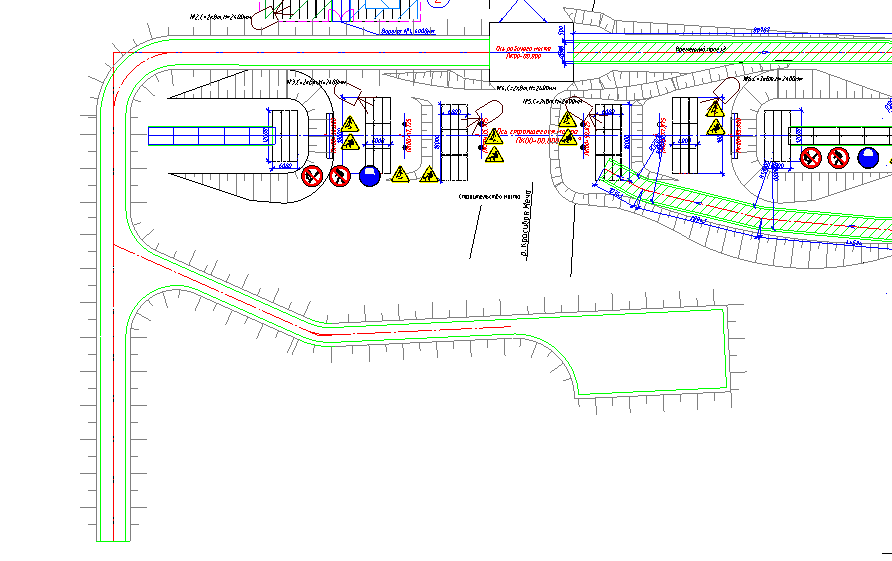
The result of laying the plates along the road and the intersection should be as shown in the figure.
3.6.Change layout options
Double-click again to edit the intersection. Change the overlap factor from 0.9 to 0.5 and lay out the plates. Please note that the number of unfolded boards has changed.
3.7. Installation of road signs and specification generation
Double-click to edit the main road. In the dialog, run the command from the menu "Insert - Insert Road Sign". Wait for the base of characters to load. In the dialog for road signs, type the expression "Speed" in the search field.

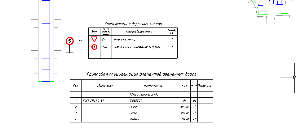
Names of characters that include this expression are highlighted in yellow. Transition by signs is carried out by buttons to the right of the search field. Go to the second sign "Maximum speed limit". Double-click to select it and click "OK." Place the sign along the road at the bottom of it. Similarly, place the “Give way” sign next to it. In the search bar, type the expression “Step” and double-click the sign, and then click “OK” and place it before the intersection.

To generate the specification of road signs, run the command "Construction Site - Reports - Specification of Road Signs". Place the table at the bottom of the drawing.
3.8. Specification of elements of temporary roads
The specification can be formed on a separate road or intersection. In order for the selected elements of roads to fall into a single specification, you must run the command "Construction Site - Reports - Specification of Roads and Sites". After starting the team, it is necessary to make a choice of those road elements on which we want to receive the specification. Point to the border of the road (by default it is marked in green) and to the border of the intersection on which the plates are laid out. Place the bill of materials at the bottom of the drawing. Materials from the indicated elements of the road got into it.
Theme 4. Selection of equipment
In this topic, we will consider the functionality of the selection of various construction equipment depending on the given criteria.
To work, you will need the file "\ Topic 4_Selection of equipment \ Task \ Selection of equipment.dwg".
4.1. Machine running
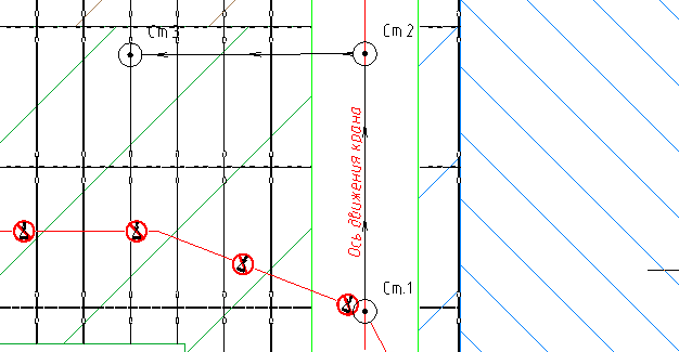
Turn on the bindings with the "Point" option and the "ORTO" mode. Run the command “Construction site - Hazardous areas - Work and idle” to set the designation of the working stroke of the crane. In the dialog, select the icon "Machine stroke". Leave other options unchanged. Indicate the first point at the intersection of the "Crane Coverage Lines" with the axis of the road, using the "Point" snap, as shown in the figure.
Point the second point at an arbitrary distance in the up direction. Point the third point to the right at a right angle, as shown in the figure.

4.2.Crane parking
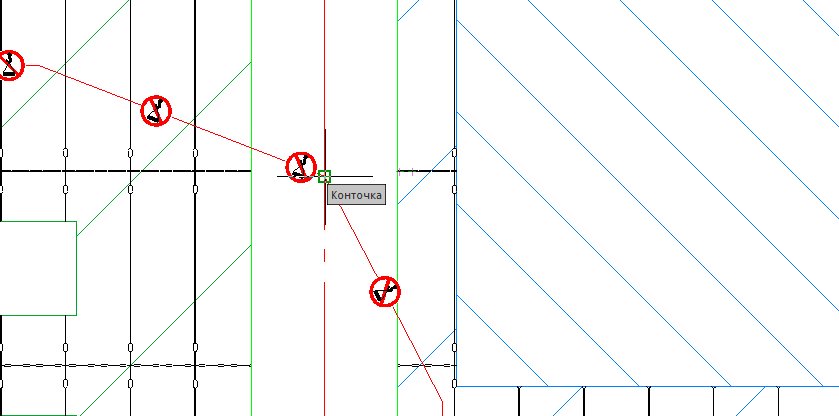
Highlight the travel symbols and click on the “+” icon to add symbols for the crane stops. Indicate the same points that you indicated to indicate the stroke. Three parking signs shall be affixed.
4.3. Truck tractor
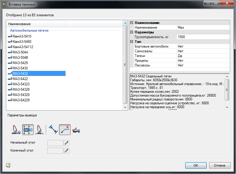
Turn on the "ORTO" mode. To install the truck tractor, run the command "Construction site - Construction equipment - Selection of automotive equipment". In the selection dialog box, set the following parameters. In the "Name" field, specify the value "Maz", for all types of equipment, except tractors, set the position to "No". In the list of filtered machines, select "MAZ-5432". In the output options, click on the icons of the top view and display the leader with the name of the machine. Turn off the rest of the icons.
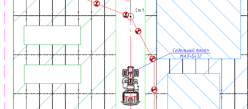
Using the binding, indicate the insertion point of the tractor on the center line of the road below the first parking lot and turn the cab down, as shown in the figure.
4.4. Car semi-trailer
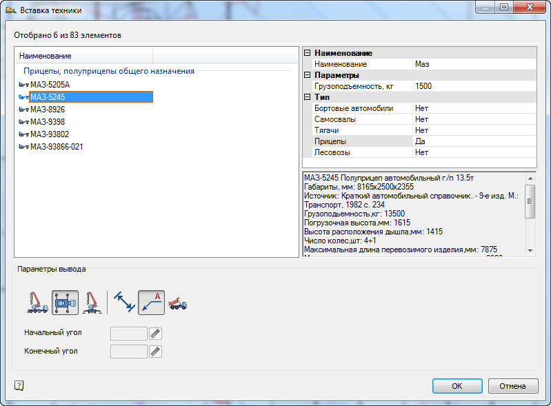
Run the command "Construction site - Construction equipment - Selection of automotive equipment." In the selection dialog box, set the following parameters. In the "Name" field, leave the value "Maz", for all types of equipment, except trailers, set the position to "No". In the list of vehicles, select "MAZ - 5245". In the output options, similarly specify the top view and leader.
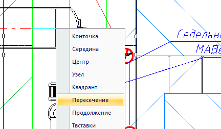
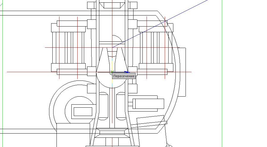
When setting up the trailer, enable one-time binding as follows. Hold Shift and right-click in the model area. In the context menu, select the Intersection snap. The snap will be active on one point indication.
Select the next point on the tractor to mount the trailer as shown.
Turn the trailer vertically up along the axis of the road. The result is shown in the figure below.

4.5.Crane Crane
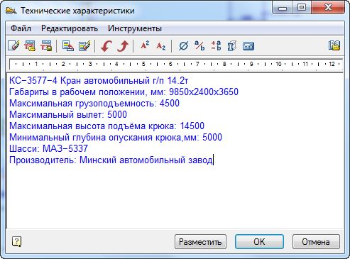
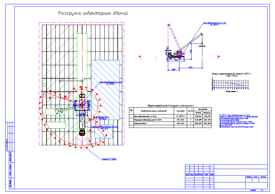
Run the command "Construction site - Construction machinery - Selection of lifting equipment." In the dialog, set only the automobile type of cranes; for the rest, set the value to "No". Set the lifting height to 2m and the hook reach to 5m. In the name field, specify the value of "COP". For cargo dimensions, set the following parameters: cargo height - 200 mm, cargo width - 2000 mm, cargo length - 3000 mm. Leave the remaining options by default. As a result of the selection, a list of suitable taps appears on the left. In the list, find the KS-3577-4 crane with a 14 m arrow. Position the cursor on the arrow. In the selection options, set all the icons except the side view. Highlight the crane technical specifications with the cursor and copy them to the clipboard by pressing Ctrl + C.

Position the side view on the right side of the drawing. Next, enable the Center one-time snap by pressing Shift + right mouse button. Indicate the crane parking lot No. 1 as the insertion point. Turn the crane so that the cab is directed upstream towards parking No. 2. In this case, the automatically activated Nearest snap will help you snap to the axis of the road. After placing the crane, place the capacity chart also on the right side of the drawing. You should get a drawing similar to the one in the figure.
4.6. Technical characteristics of the crane
Call the text editor from the menu "SPDS - Text - Tech. specifications". Delete the numbered paragraph of the first line and press Ctrl + V to paste the copied crane characteristics from the clipboard.
Click “OK” and place the text above the stamp in the drawing, indicating two diagonal points for it.
4.7. Hook Departures and Boom Angles
Select the type of crane on the plan, pointing to its cabin, for example. You will find three characteristic handles - the axis of the crane and two hook hooks. Press the handle on the left and pull it to the middle of the semi-trailer. Similarly, pull the right departure handle to the storage area. Please note that the working and hazardous areas have changed automatically.

Similarly, you can edit the section view. Grasp the handle located on the hook and pull it to the side. Position the departure at the desired distance. Pay attention to changing zones and sizes.

4.8.Hazardous area of the crane
Select the dangerous zone of the crane operation with the mouse and call the context menu by right-clicking. Call up the top position “Edit”. The danger zone editing dialog opens. For the method of building the sector, select "Concentric".

Click “OK” and pay attention to the change in the shape of the danger zone.
4.9. Need for machines and mechanisms
Call the Project Manager through the menu “Construction Site - Project Manager”. On the “Jobs” tab, position the cursor on the heading of the 3rd section “Lifting, lowering loads by self-propelled jib cranes”. Call the command “Reports - List of machines and mechanisms”.
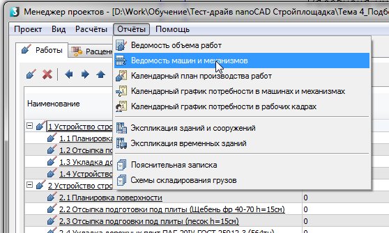
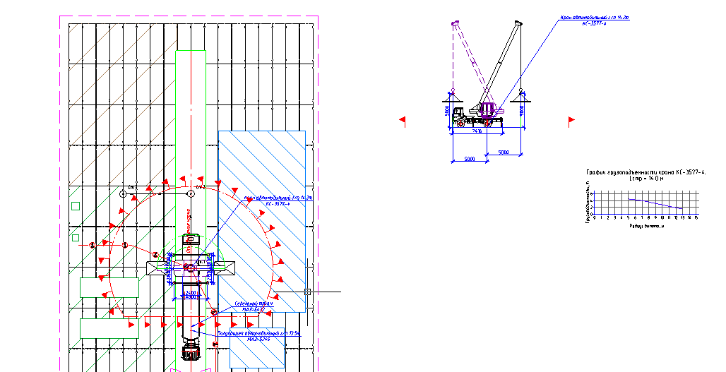
Place the statement on the drawing. The result of this topic is shown in the figure below.
Recordings of past webinars can be viewed on our YouTube channel .
More information on spds.club
Olga Artemyeva, Head of Software Development