We play Tetris on the electromechanical screen
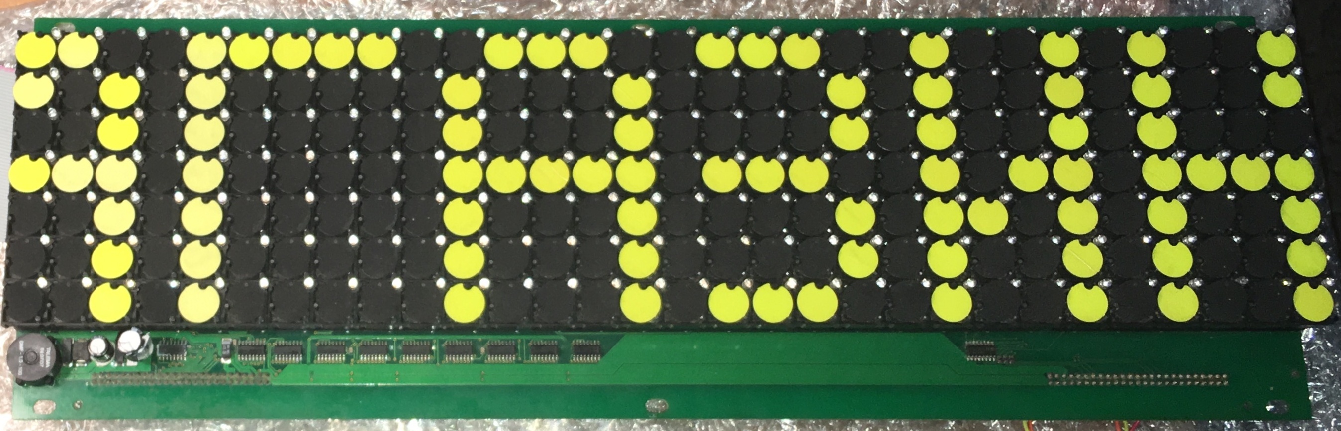
One day, looking at ads on Avito, I came across a very interesting thing - a blinker board or flip-dot display in English. Such displays are used to display information at airports, train stations, stadiums or route indicators on public transport.
I thought that with this type of display you can do a lot of interesting things.
Where my screen was installed, one can only guess from the rest of the inscription (“STORE”). Perhaps it was an information stand at the train station or OT stop - write your ideas in the comments.
The screen was a matrix of cells measuring 7 rows by 30 columns. Each cell contained a round, rotating two-color plate and a green LED. The board had a certain number of logic elements of the 74HCxxx series and other microcircuits, which, as it turned out, was almost enough to control the screen through a simple serial interface.
After the purchase, I spent a little time searching for information on how to work with such screens, given that I only had the part that directly displays the image, and usually there is also a controller that can control the keyboard or through the UART port with PC software .
It was not possible to determine the manufacturer’s affiliation by the inscriptions on the board, but maybe I didn’t try hard, because it was more interesting to figure out how it works, draw a diagram of the device and develop a module for interfacing with a typical microcontroller.
But first, you had to set yourself a specific goal, for which you can apply this screen in everyday life. The first idea was a watch displaying extended information about weather on the street and at home, time, date, short motivating messages;), etc. Then I thought that if you rotate the screen 90 ° , it looks like a glass for Tetris, so it was decided to make Tetris, and then it will be seen.
How do electromechanical screens work?
Very simple: each screen cell (check box) consists of a disk - a flat permanent magnet painted yellow on one side and black on the other, and an electromagnet located under the disk. When applying an electrical impulse to the coil of the electromagnet, the flag flips over and, importantly, is fixed in one position. When changing the direction of the current and applying a repeated pulse, the flag is rotated and fixed by the other side. For switching, a pulse with a duration of 1 millisecond and a voltage of 12 volts is enough.
The resistance of an electromagnet coil is approximately 18 ohms.
 Cell Device, Source: Eldi datasheet | 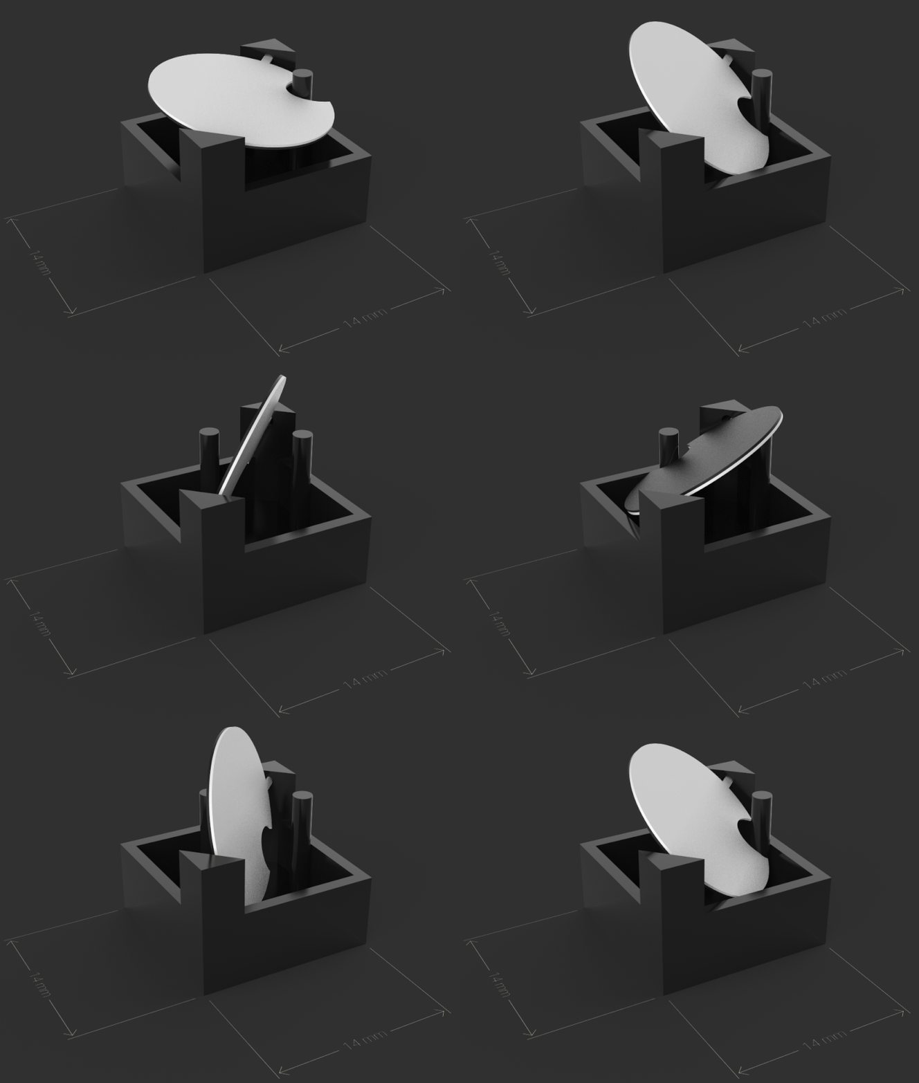 How does the disk rotate, source: Flip-Disc Display |
For convenience, the coils through two diodes are combined into a matrix of rows and columns. To switch anywhere on the screen, you need to activate the current source (current source) on the line and the current sink (current sink) on the row, at the intersection of which there is an electromagnet coil or, conversely, to switch to the other side. In fact, this is similar to controlling DC motors through an H-bridge, only in pulsed mode.
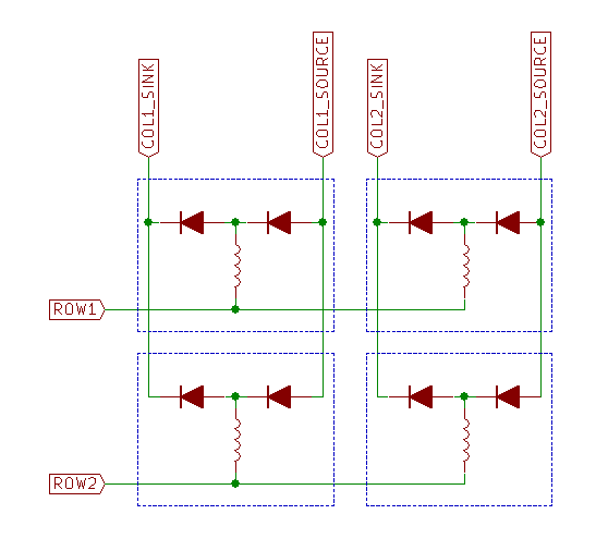
With how to manage flags in theory, we figured out. It's time to move on to practical implementation.
Screen reverse engineering
Armed with a multimeter and Kicad, I began to redraw the screen layout, starting with controlling the LEDs. It turned out that this part is self-sufficient, and when applying power and control signals, you can light any LED in any row of the screen through a fairly simple interface. Only one line can be active at any time, so the output of the image must be dynamic.
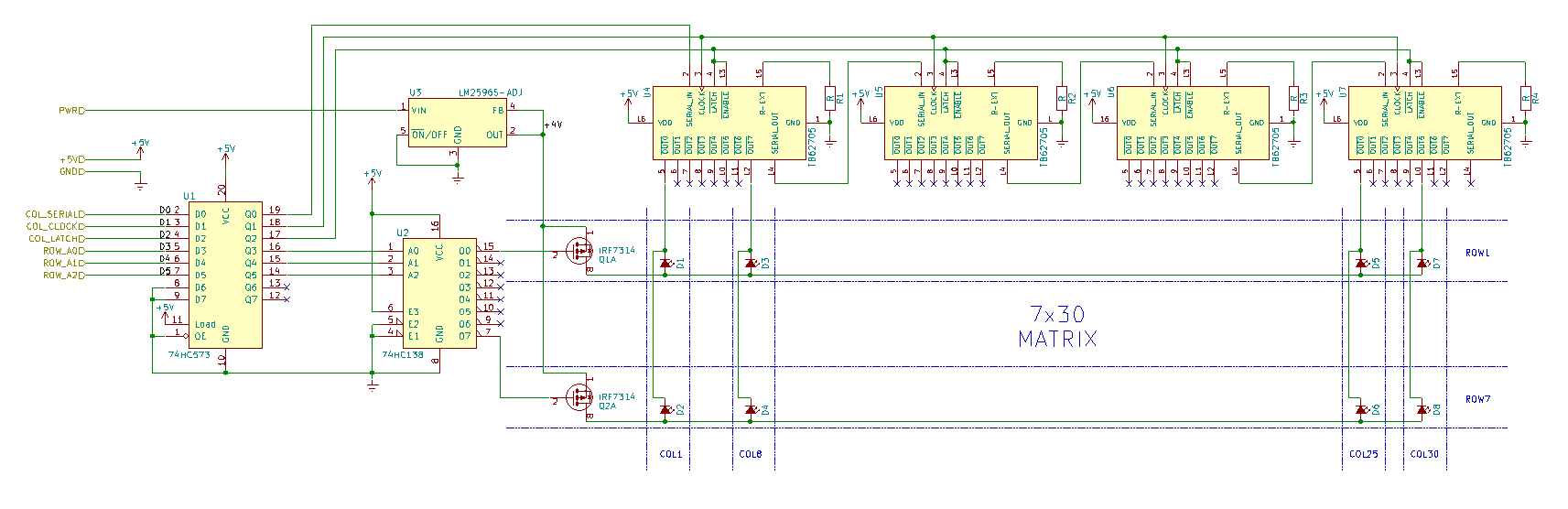
The module circuit consists of a matrix of LEDs whose cathodes are connected to the Toshiba TB62705 LED drivers. From the point of view of control logic, these are ordinary 8-bit shift registers connected in a chain. The anodes of the LEDs in each row are connected and connected to the drains of the MOSFET transistors. The sources are connected to the output of the DC-DC converter, and the gates of all 7 transistors are connected to the outputs of the 3: 8 74HC238 decoder.
Thus, to control the LEDs, you need to select the screen line by submitting its number to the decoder input, then load 32 bits of data through the SERIAL and CLOCK inputs of the first LED driver. Then file the log. “1” to the LATCH input, and the corresponding LEDs light up while holding the LATCH to “1”.
To blink the LEDs, I used the on-board arduino-compatible boardTeensy 3.5 . An example of LED control code can be found on GitHub
The second part of the scheme, responsible for managing blinkers, is a bit more complicated.

The power part of the speaker control consists of a pair of current source / sink circuits, the outputs of which are connected through protective diodes to the first output of each coil in the column. The Toshiba TBD62783 chip was used as a current source, and TI's favorite ULN2803 was used as a drain. The second conclusions of the coils are combined in rows and connected to the connector on the screen board. Apparently, this was done in order to take out string management in a separate module, since several screens can be combined into one long screen. However, it is not clear why the developers placed all the necessary components on each screen board to control the LEDs.
The logic consists of eight 3: 8 decoders 74HC238, the control inputs of which are connected in parallel. The outputs of the even decoders are connected to the control inputs of the current sources, and the odd ones are connected to the inputs of the drains. The permissive inputs of the 74HC238 are connected to another 3: 8 decoder, which completely eliminates the situation when the current source and current circuits are active at the same time. The enable input of the common decoder is connected to the comparator chip and is activated only when the values at its input match. This part of the diagram is most likely also responsible for combining several modules into one large screen.
Thus, to select a specific column, you need to send its number (0-7) in the group to the COL_A0-A2 bus, and then activate the outputs of the specific 74HC238 by supplying its number to the inputs COL_EN_A0-A2 of the common decoder. Moreover, the input A0 can be used as a source / sink indicator, and the remaining 2 bits - as a group number (0-3).
The control logic and power inputs are routed to two 50-pin IDC connectors. The wiring of one of them is shown in the diagram.

After analyzing the circuit, I realized that blinking the flags without the help of Kicad and a soldering iron did not work, and proceeded to create a module for selecting strings and pairing.
Adapter Module and String Management
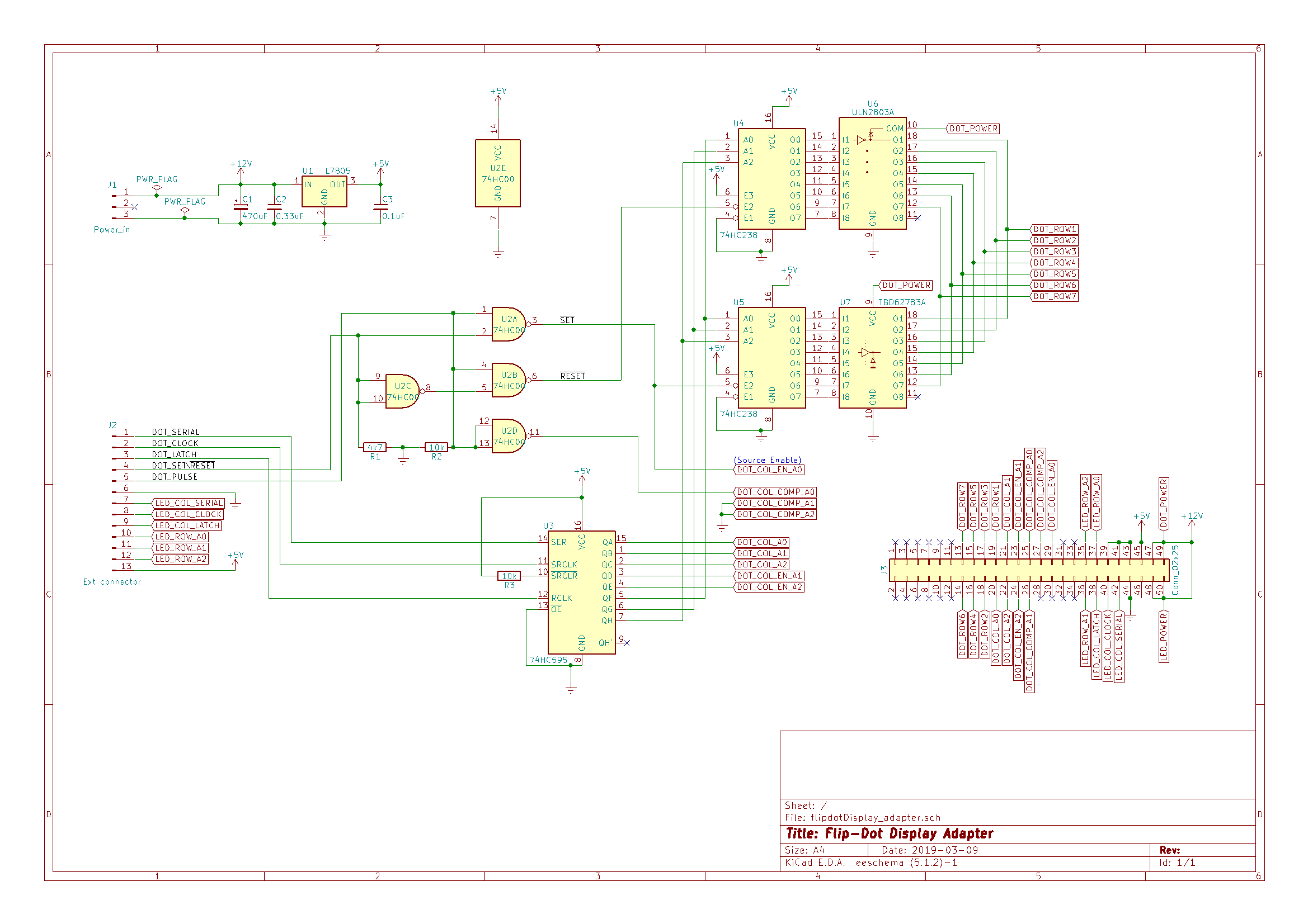
To simplify the design, I decided to repeat the implementation of the column choice and placed on the circuit TBD62783 and ULN2803 paired with 74HC238 decoders to select the desired line, as well as one 74HC00 logic chip (4xNAND) to clearly separate the SET, RESET and PULSE modes, which directly activate the voltage supply to the selected electromagnet. To save the conclusions of the microcontroller, it was decided to connect the row and column selection signals to the outputs of one shift register.
As a result, to manage the flag you need:
- send and fix its coordinates in serial code via SERIAL / CLOCK / LATCH
- select desired SET / RESET state
- briefly activate PULSE
Decoding of the coordinate byte:

The first version of the circuit without a shift register was assembled on a solderless breadboard. After checking and a little excitement that everything will burn, I turned on the power and manually pulsed a PULSE pulse with a quick press of a button. The current flowing through the coil of the electromagnet was just in case limited to a laboratory power source. The checkbox switched successfully, and when changing the SET / RESET level, it switched back. “This is a success,” I thought, and began to transfer the circuit to a regular breadboard using my favorite MGTF-0.07 and a single-core kynar-wire for power / ground buses.
To connect to the screen through the 50-pin connector on the board, it was necessary to use 22 contacts + power, so I did not want to mess with individual wiring. The use of a flat cable, for IDE or, rather, old SCSI devices, was suggested.
A little googling brought me to a special tool for crimping IDC connectors, which it was decided to immediately buy: Crimper ProsKit 6PK-214 for IDC connectors . Having trained on small connectors, the first time I made myself a 20-centimeter loop with IDC-50F connectors at the ends.
We write a control program
As I mentioned above, TEENSY 3.5 was used as the control controller, the development environment for which is the Arduino IDE, so the program was written in the arduino dialect C.
The main function of changing the state of a screen point
void update_dot(bool state, byte row, byte col) {
  byte cmd=0;
  // set 7-5 cmd bits to row 2-0 bits
  cmd=(row&B111)<<5;
  // set 4-0 cmd bits to col 4-0 bits
  cmd=cmd|(col&B11111);
  // write to Register
  digitalWriteFast(DOT_LATCH,LOW);
  for (byte i=0;i<8;i++) {
    byte onebit=bitRead(cmd,7-i);
    digitalWriteFast(DOT_CLOCK,LOW);
    digitalWriteFast(DOT_SERIAL_DATA,onebit);
    digitalWriteFast(DOT_CLOCK,HIGH);
  }
  digitalWriteFast(DOT_LATCH,HIGH);
  delayMicroseconds(10);
  digitalWriteFast(DOT_LATCH,LOW);
  // set set/reset pin
  if (state) {
    digitalWriteFast(DOT_SET_RESET,HIGH);
  }
  else {
    digitalWriteFast(DOT_SET_RESET,LOW);
  }
  // pulse
  digitalWriteFast(DOT_PULSE,HIGH);
  delay(1);
  digitalWriteFast(DOT_PULSE,LOW);
}
I conducted several experiments to determine the optimal voltage of the power source and the pulse feed time. It turned out that 12V and 1ms are enough for stable fixation of the flag in one of the positions.
After the test fills with one color, I noticed that one “pixel” is broken and does not flip. Measurement of the coil resistance with a multimeter showed several megaohms, and a detailed examination revealed that one conclusion came off. It was very lucky that the non-working “pixel” was from the edge of the screen, so I managed to solder the wire. The problem was solved.
Photo of the repaired cell
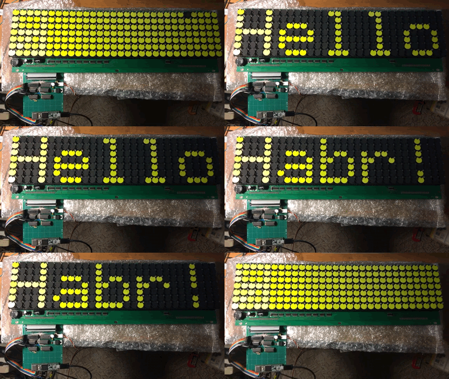
Here's what happened after the first experiments with fills and text output:
Tetris
Writing a Tetris implementation in C was easier than I thought. Thanks to Javier López and his tutorial Tetris tutorial in C ++ for beginners . I rewrote the main functions as I understood them, and adapted the code to the features of my screen (lack of borders and low resolution). I will not bore the details of the work, the manual describes everything in detail.
For control, an analog joystick module was used, so I had to write a function to convert the values at the ADC output to digital constants. There was a difficulty in order, on the one hand, to prevent false positives, and on the other, to ensure the correct gameplay. If the position of the joystick does not change after the next reading of the state, a delay is added.
After playing for about 10 minutes, I realized that I was bored, because the speed of falling shapes does not change and the score is not displayed at all. There is no competition element.
Displaying an account with flags was ugly due to lack of space on the screen, so it was decided to use LEDs to create an alternative plane for displaying information. I found on the Internet a bit representation of the 3x5 font for numbers from 0 to 9 and wrote a function to display the score by the number of lines removed. For greater beauty, I decided to add the blinking of the filled line when it disappears.
The dynamic nature of the display prompted the idea to call the update function of the LED part of the screen in a timer interrupt. The interruption frequency and the holding time of the LED string in the active state determine the brightness of the glow.
I also made it so that the falling speed of the tetramino figures increases as the lines are cleared. In the first version, the figures were shifted one line down every 200 ms. If you take away from this number 40 ms every 10 deleted lines, then the pace of the game is greatly accelerated, and there is interest. My record is 38 lines!
That rare case when vertical video fits perfectly.
The project code , screen layout and interface module are posted on GitHub.
If you have any ideas what else you can do with such a screen, please write in the comments.
Useful links:
1. Hackaday: Flip-Dot Display & DIY Controller .
2. Tetris tutorial in C ++ platform independent focused in game logic for beginners .
3. Project repository on GitHub .