Hobby CNC router do it yourself. Humanities for humanities. Part 2
As I wrote in the previous chapter, initially my future supercar was supposed to be plywood. And I even wondered where I would glue in additional braces and stiffening ribs, but then somehow I introduced myself how I saw 4/4 plywood with Chinese lobzdik, wept and went for iron.
The budget at that time allowed the profile pipe 50x50x2.5, angle 50x50x3, strip 40x4. Not thickly, but, after watching how people sculpt their works from chipboard and furniture guides, to portals with a length of one and a half meters, consisting of two unrelated aluminum profiles with a thickness of 40 mm, despite the fact that it also somehow manages something to cut, I hoped that my taratyka somehow, yes cope. Now I can say that it was necessary to take a thick-walled pipe 50x50x6, which would allow to avoid additional perverted relations with mortgage strips, but at that time I was a prisoner of cheap bricks, and what was done was done.
The project at that time looked like this:
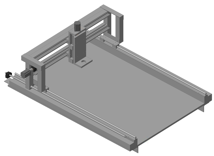
Initially it was assumed that the portal would consist of two unrelated beams, reinforced by a corner.

The corner increased the stiffness of the beams and allowed to bring the front face more or less into one plane. Here it should be remembered that the composite structure with the same dimensions is always inferior in monolithic stiffness, but such a stiffener is better than nothing. In addition, this corner weights the portal for five kilograms, and the heavier the design, the less it reacts to high-frequency vibrations. What is also beneficial to the accuracy of processing. The corner to the pipe screwed on the M8 bolts, the distance between the holes - 90 mm.
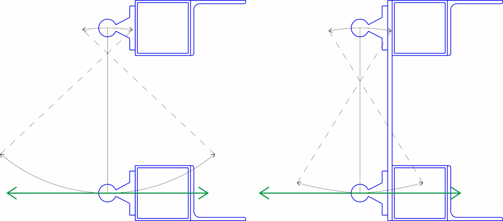
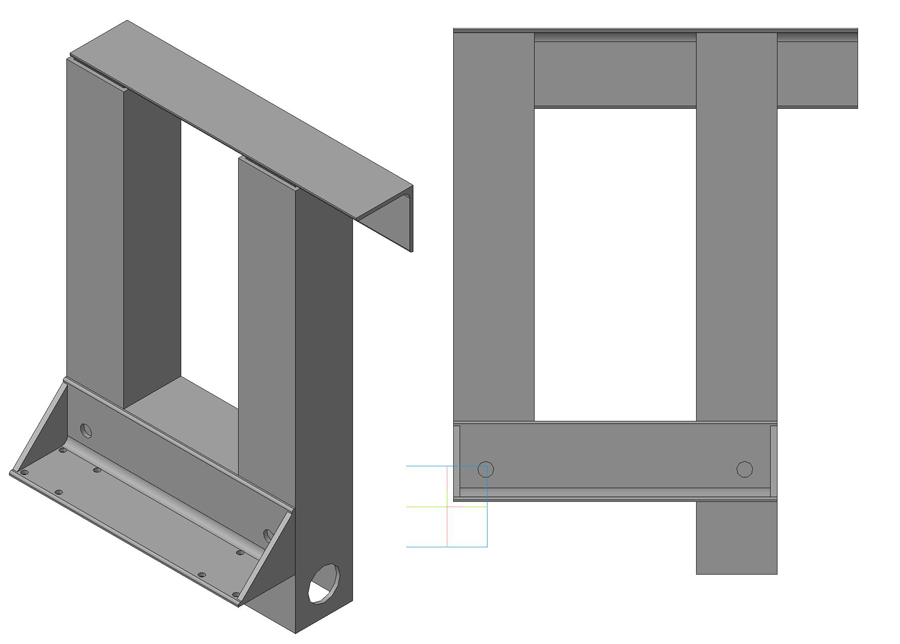
Later, I decided that the beams that were not connected with each other would still chatter, and tied them with a sheet of iron 4 mm thick. As the title implies, I have not studied the strength of the material, but common sense dictates that such a design allows the bending force to be partially redistributed to the upper beam and avoids the portal slack. I do not own a conceptual apparatus, and it is difficult for me to explain with words, therefore I illustrate my thoughts with a drawing.
Separately, it is necessary to mention that the portal beams did not weld together. Welding is a thermal effect, internal stresses occur in the metal, as a result, the design leads. When I figured that the sidewalls of the portal, which had also been tied to bolts before, could be boiled, and the welder convinced me that he was well able to cook in such a way so as not to lead, after installing the 1.5-meter guides X on the frame, ran for five seconds. over centimeters. Cured with shims.
The placement of the corners for fastening the beams to the sides is shown in the following figure:
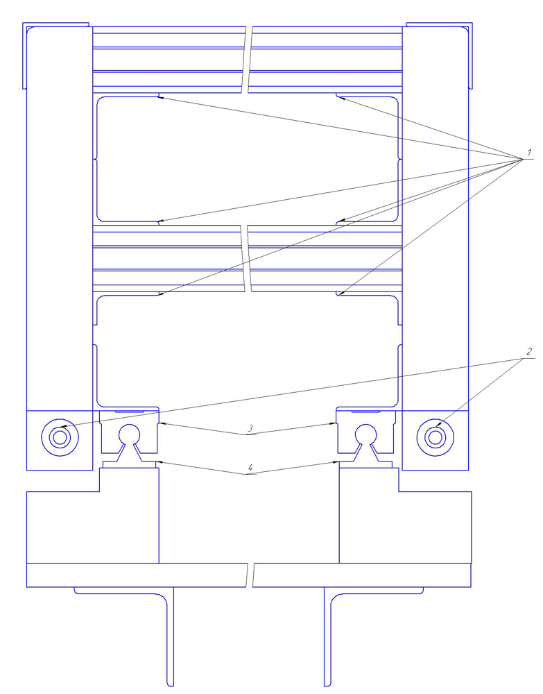
1 - The corners of the portal beams to the sides. Corner 50x50x3 mm. 2 - X-axis ball screws.
3 - X-axis bearing carriages. 4 - X-axis guides.
Used for mounting bolts M8. In the short corners, one per edge, the rear corners are bolted to the gantry poles, two bolts per side. The front four-millimeter sheet is bolted to the beams on the M6 bolts through 90 mm, and six bolts staggered to the portal posts.
Before installing the guides, I checked the curvature of the front side of the portal. For what he took in a fishing line-braided with a thickness of 0.1 mm, and, pressing it at the edges of the portal through the same pads, checked the clearance with a metal line. Or my eyes lie, or the fishing line is now stretched by an arc, but with the curvature of the portal I fit into the top ten. What I was surprised and delighted. I suspect that a corner has played its role. And although I screwed the adjusting bolts into the back wall in order to squeeze the front wall, none of them came in handy. Last time in the comments they asked whether it was possible to increase the accuracy of this design, I think that it is already impossible. In order to bring the surface "to zero", it is already necessary to mill. And there is no point in milling thin iron, therefore, to increase accuracy, you will have to build a new portal. AND,
At the design stage of the project in order to imagine what to expect from the invented construction, I launched a strength analysis at APM FEM.
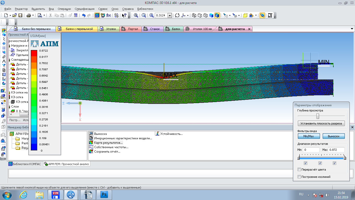
With a load of 200 Newtons on the front side of the portal (I just had no idea what the load would be, and decided that obviously not more than twenty kilograms), the beams deflected about 0.6 mm. In fact, when I placed the portal on my back on two stands and stood in the middle with one foot (110 kg at the time), I received a 0.9 mm deflection before installing the guides. I put a ten-liter bucket with water - 0.04 mm.
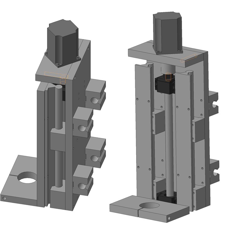
Having finished with a beam, we start sides. We make from the same materials. The device is clear from the figure, it is only necessary to emphasize that the back leg of the sidewall is 50 mm longer than the front foot. That allows you to install the nuts of the ballscrew on the same level with the X-axis carriages. The carriage holder is screwed to the sidewalls on the four M8 bolts. All openings in the holder are bored out to allow adjustment. Also, two stiffening ribs are welded to the carriage holder in order to reduce lateral vibrations.
The distance between the outer edges of the carriages was initially speculatively chosen 200 mm, but after assembling the portal and assessing its rigidity, it was reduced to one hundred and fifty millimeters.
Z axisIt was originally planned out of plywood, since financial limits were chosen long and many times, but the construction plywood, which is available here, floats in thickness by almost a millimeter. So I decided to buy duralumin. Chose plate D16 16 mm thick. Guided by considerations that even soft metal will still be stiffer than plywood of the same thickness. So it actually happened. When processing it is necessary to take into account that the metal, although soft, is very viscous. Strongly sticks to the instrument, literally grabbing it. When I first drilled it with a Christmas-tree drill without lubrication, I almost burned an eight-hundred-watt drill. He cut out a tooth on a circular tooth with a tooth with a pokavitovy napayka, plentifully pouring it with oil. After adjusted grinder with a flap wheel. Although we have in the area two machinery plants and two workshops for metalworking, place an order and failed. Neither officially nor the left way.
The design of the Z axis is classic, the only difference is that the bearing carriages are mounted on the Y-axis trolley, and the rails, respectively, on the Z-axis trolley. I have heard various arguments in favor of this solution, but the only thing that looks like the guides in this case plays the role of additional edges stiffness. It should be added that such a decision makes the Z-axis weigh almost three kilograms. That requires additional engine power. I have a NEMA-23 with a length of 112 mm, and still the speed of movement along Z is 20 mm / s. It is not critical for cutting, but if a normal spindle is installed and reliefs are processed, it will be necessary to invent a counterweight.
Since a hand mill is used as a spindle, a shelf was installed under it. Landing diameter of this mill is 43 mm. When I ordered (seventy kilometers from the house) drilling the shelf under the spindle, I ordered a diameter of 44 mm. It's a lot. Add two or three tenths would be more than enough. To strengthen the shelf, as well as to adjust it on the sides, two additional ribs 4 mm thick were additionally installed.
Choosing the diameter of the bolts for soft metals, it should be remembered that one bolt with a larger diameter and thread pitch is preferable here than a few small ones. Therefore, the Z axis, excluding fastening of the carriages and guides, is assembled on screws M10. And it is better not to twist them once again, ideally having assembled the construction immediately at once.
When it came to the bed, on the one hand, money was already needed for other purposes, and on the other, I began to get specifically tired of continuous drilling, turning and fitting. Therefore, I chose a compromise-temporary option: I arranged a sand pillow on the floor, laid out a block from the foam block, and installed a four-layer 18/4 plywood sandwich on each side of the unit, reinforced on each side with a 75x75x6 mm corner. On top put two more sheets of the same plywood. Platforms for guides installed so that the bolts pull them to the corners under the table. In the areas provided for embedded strips, which were bolted guides.
First set the guide one, putting it on a thread. After that, a portal was installed on it, and the second guide was placed in place. That is, you install the portal at the beginning of the axis, the first guide is fixed rigidly, the second one with one edge. We drive the portal to the end of the axis, we make sure that it is easy, we fix the second edge. We roll along the entire axis, fixing the guide completely. So, by the way, guides are installed on all axes.
After installing the guides directly over them, I pulled the threads across the table crosswise. With the help of the level of jacks, he first set the table horizontally, then, having achieved that the threads at the intersection lightly touched, straightened the small screw curvature. The gap between the table and the cabinet was slightly bitten to bind them, but so that the table did not lift.
Actually, with the mechanics on it all. On the video, however, it is clear that the cable channels have not been completed yet (despite the fact that they have already been sawed long ago and even partially glued together), and there are no limit switches, but I need to get some rest from it. It was very interesting, but very tedious.
Add a few words about the project errors . First, yielding to the inertia of thinking, I for some reason designed the cable channel from the operator’s side, and now after installing it, I’ll have to drive the portal back and forth to install the workpiece, and second, for some reason I put the nut of the ball screw Y in the middle of the axis Z. Now I can not get to the grease box, and when the boot jumped out of the nut, I had to disassemble the entire portal.
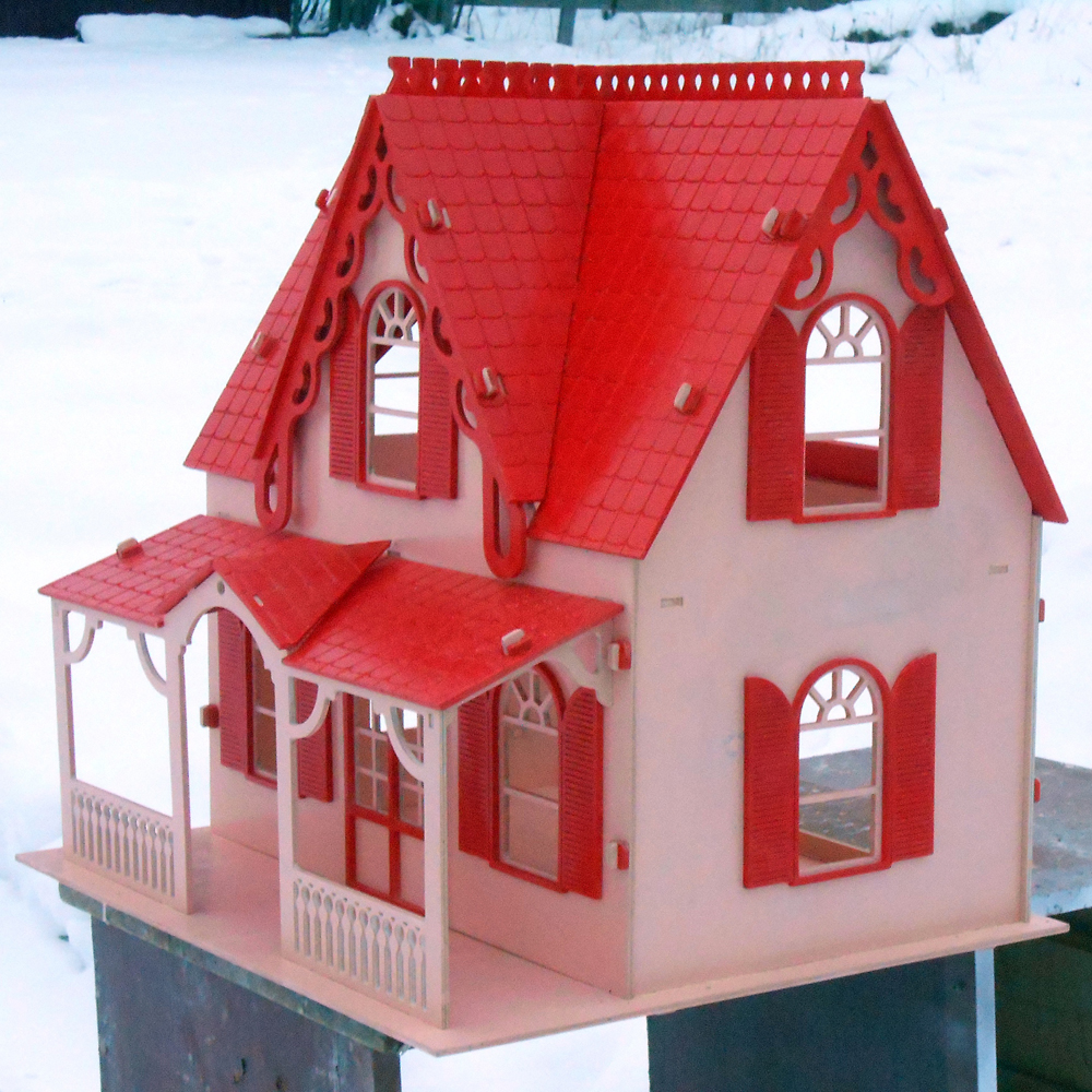
In conclusion, here is a photo of the first project executed on this machine, on which I was once again convinced that you will get nothing good from cheap plywood.
Video of my machine:
Video homemade machine healthy person:
The budget at that time allowed the profile pipe 50x50x2.5, angle 50x50x3, strip 40x4. Not thickly, but, after watching how people sculpt their works from chipboard and furniture guides, to portals with a length of one and a half meters, consisting of two unrelated aluminum profiles with a thickness of 40 mm, despite the fact that it also somehow manages something to cut, I hoped that my taratyka somehow, yes cope. Now I can say that it was necessary to take a thick-walled pipe 50x50x6, which would allow to avoid additional perverted relations with mortgage strips, but at that time I was a prisoner of cheap bricks, and what was done was done.
The project at that time looked like this:
Initially it was assumed that the portal would consist of two unrelated beams, reinforced by a corner.
The corner increased the stiffness of the beams and allowed to bring the front face more or less into one plane. Here it should be remembered that the composite structure with the same dimensions is always inferior in monolithic stiffness, but such a stiffener is better than nothing. In addition, this corner weights the portal for five kilograms, and the heavier the design, the less it reacts to high-frequency vibrations. What is also beneficial to the accuracy of processing. The corner to the pipe screwed on the M8 bolts, the distance between the holes - 90 mm.
Later, I decided that the beams that were not connected with each other would still chatter, and tied them with a sheet of iron 4 mm thick. As the title implies, I have not studied the strength of the material, but common sense dictates that such a design allows the bending force to be partially redistributed to the upper beam and avoids the portal slack. I do not own a conceptual apparatus, and it is difficult for me to explain with words, therefore I illustrate my thoughts with a drawing.
Separately, it is necessary to mention that the portal beams did not weld together. Welding is a thermal effect, internal stresses occur in the metal, as a result, the design leads. When I figured that the sidewalls of the portal, which had also been tied to bolts before, could be boiled, and the welder convinced me that he was well able to cook in such a way so as not to lead, after installing the 1.5-meter guides X on the frame, ran for five seconds. over centimeters. Cured with shims.
The placement of the corners for fastening the beams to the sides is shown in the following figure:
1 - The corners of the portal beams to the sides. Corner 50x50x3 mm. 2 - X-axis ball screws.
3 - X-axis bearing carriages. 4 - X-axis guides.
Used for mounting bolts M8. In the short corners, one per edge, the rear corners are bolted to the gantry poles, two bolts per side. The front four-millimeter sheet is bolted to the beams on the M6 bolts through 90 mm, and six bolts staggered to the portal posts.
Before installing the guides, I checked the curvature of the front side of the portal. For what he took in a fishing line-braided with a thickness of 0.1 mm, and, pressing it at the edges of the portal through the same pads, checked the clearance with a metal line. Or my eyes lie, or the fishing line is now stretched by an arc, but with the curvature of the portal I fit into the top ten. What I was surprised and delighted. I suspect that a corner has played its role. And although I screwed the adjusting bolts into the back wall in order to squeeze the front wall, none of them came in handy. Last time in the comments they asked whether it was possible to increase the accuracy of this design, I think that it is already impossible. In order to bring the surface "to zero", it is already necessary to mill. And there is no point in milling thin iron, therefore, to increase accuracy, you will have to build a new portal. AND,
At the design stage of the project in order to imagine what to expect from the invented construction, I launched a strength analysis at APM FEM.
With a load of 200 Newtons on the front side of the portal (I just had no idea what the load would be, and decided that obviously not more than twenty kilograms), the beams deflected about 0.6 mm. In fact, when I placed the portal on my back on two stands and stood in the middle with one foot (110 kg at the time), I received a 0.9 mm deflection before installing the guides. I put a ten-liter bucket with water - 0.04 mm.
Having finished with a beam, we start sides. We make from the same materials. The device is clear from the figure, it is only necessary to emphasize that the back leg of the sidewall is 50 mm longer than the front foot. That allows you to install the nuts of the ballscrew on the same level with the X-axis carriages. The carriage holder is screwed to the sidewalls on the four M8 bolts. All openings in the holder are bored out to allow adjustment. Also, two stiffening ribs are welded to the carriage holder in order to reduce lateral vibrations.
The distance between the outer edges of the carriages was initially speculatively chosen 200 mm, but after assembling the portal and assessing its rigidity, it was reduced to one hundred and fifty millimeters.
Z axisIt was originally planned out of plywood, since financial limits were chosen long and many times, but the construction plywood, which is available here, floats in thickness by almost a millimeter. So I decided to buy duralumin. Chose plate D16 16 mm thick. Guided by considerations that even soft metal will still be stiffer than plywood of the same thickness. So it actually happened. When processing it is necessary to take into account that the metal, although soft, is very viscous. Strongly sticks to the instrument, literally grabbing it. When I first drilled it with a Christmas-tree drill without lubrication, I almost burned an eight-hundred-watt drill. He cut out a tooth on a circular tooth with a tooth with a pokavitovy napayka, plentifully pouring it with oil. After adjusted grinder with a flap wheel. Although we have in the area two machinery plants and two workshops for metalworking, place an order and failed. Neither officially nor the left way.
The design of the Z axis is classic, the only difference is that the bearing carriages are mounted on the Y-axis trolley, and the rails, respectively, on the Z-axis trolley. I have heard various arguments in favor of this solution, but the only thing that looks like the guides in this case plays the role of additional edges stiffness. It should be added that such a decision makes the Z-axis weigh almost three kilograms. That requires additional engine power. I have a NEMA-23 with a length of 112 mm, and still the speed of movement along Z is 20 mm / s. It is not critical for cutting, but if a normal spindle is installed and reliefs are processed, it will be necessary to invent a counterweight.
Since a hand mill is used as a spindle, a shelf was installed under it. Landing diameter of this mill is 43 mm. When I ordered (seventy kilometers from the house) drilling the shelf under the spindle, I ordered a diameter of 44 mm. It's a lot. Add two or three tenths would be more than enough. To strengthen the shelf, as well as to adjust it on the sides, two additional ribs 4 mm thick were additionally installed.
Choosing the diameter of the bolts for soft metals, it should be remembered that one bolt with a larger diameter and thread pitch is preferable here than a few small ones. Therefore, the Z axis, excluding fastening of the carriages and guides, is assembled on screws M10. And it is better not to twist them once again, ideally having assembled the construction immediately at once.
D16 took in Izhevsk. A 16x1200x150 mm plate weighing 9 kilograms together with a sharp cost of 3050 rubles. In general, advertising probably violates the rules of the site, but in this case it’s just the only adequate seller I’ve found. Traded by the kilogram. Prices for the same position they turned out to be the lowest. The only thing I did not like then, work only with transport companies. And since I do not live in the regional center, and to the point of issue to me more than a hundred kilometers, I tried to find a supplier closer. In our (Perm) region, the seller offered the same metal only in pieces from half a meter long, requesting 25,000 rubles for such a piece. After that, the choice was obvious. I then cut off the stove grinder. Now when ordering it is necessary to clarify, it seems they have the equipment, and you can order cutting by size.Finishing the portal theme, it is necessary to mention that some hobbyists place guides on the upper and lower edges of the portal beam. Argued by the fact that when the load on the mill is reduced, the distance between the applied force and the portal. Simply put, the lever decreases. However, this complicates the transfer, the moving axis, and the installation of parallelism of the guides. Unfortunately, now I can’t find the source used in the design, in which it was stated that, for protection against skewing, firstly, the propulsor should be located in the same plane with the carriages at the same distance from them, and secondly, the distance between the external faces of the carriages should be no less than the distance between the rails. It was necessary to read, when by experience they found out that along the X axis, with a table width of up to sixty centimeters, one propulsor can be used, but here I have the distance between the guides on X about a meter, the distance between the outer edges of the carriages is 150 mm, while the skewing is almost three centimeters wedging. Perhaps, on the guides, HGR is different, but for cylindrical bearings on a support along the X axis, it is still necessary for a propeller on each side. Not to find out later why the machine cuts ovals instead of circles.
When it came to the bed, on the one hand, money was already needed for other purposes, and on the other, I began to get specifically tired of continuous drilling, turning and fitting. Therefore, I chose a compromise-temporary option: I arranged a sand pillow on the floor, laid out a block from the foam block, and installed a four-layer 18/4 plywood sandwich on each side of the unit, reinforced on each side with a 75x75x6 mm corner. On top put two more sheets of the same plywood. Platforms for guides installed so that the bolts pull them to the corners under the table. In the areas provided for embedded strips, which were bolted guides.
First set the guide one, putting it on a thread. After that, a portal was installed on it, and the second guide was placed in place. That is, you install the portal at the beginning of the axis, the first guide is fixed rigidly, the second one with one edge. We drive the portal to the end of the axis, we make sure that it is easy, we fix the second edge. We roll along the entire axis, fixing the guide completely. So, by the way, guides are installed on all axes.
After installing the guides directly over them, I pulled the threads across the table crosswise. With the help of the level of jacks, he first set the table horizontally, then, having achieved that the threads at the intersection lightly touched, straightened the small screw curvature. The gap between the table and the cabinet was slightly bitten to bind them, but so that the table did not lift.
Actually, with the mechanics on it all. On the video, however, it is clear that the cable channels have not been completed yet (despite the fact that they have already been sawed long ago and even partially glued together), and there are no limit switches, but I need to get some rest from it. It was very interesting, but very tedious.
Add a few words about the project errors . First, yielding to the inertia of thinking, I for some reason designed the cable channel from the operator’s side, and now after installing it, I’ll have to drive the portal back and forth to install the workpiece, and second, for some reason I put the nut of the ball screw Y in the middle of the axis Z. Now I can not get to the grease box, and when the boot jumped out of the nut, I had to disassemble the entire portal.
In conclusion, here is a photo of the first project executed on this machine, on which I was once again convinced that you will get nothing good from cheap plywood.
Video of my machine:
Video homemade machine healthy person: