WiFi Exhaust Fan Controller
Almost two years have passed since the manufacture of the humidity control controller for the bathroom . All this time, the controller served faithfully without glitches and freezes, as befits a good device, and even got a glamorous handmade case from the hands of my wife.
But technological progress inexorably runs forward, and new trends again haunted me. I have long nurtured the idea of implementing the concept of a smart home on WiFi modules ESP8266. He experimented with these modules for some time and now decided to transfer his “smart home” to them.
The main goal of the project was the implementation of new features, which in the future I will use in other devices.
So, what will the upgrade of the fan controller on the ESP8266 give me?
New opportunities
- View all indicators on WiFi from a computer / tablet / phone.
- Processing of additional parameters - operating time of the fan and the burning time of the lamp in the bathroom.
- WiFi fan control from computer / tablet / phone.
- Setting up the controller over WiFi with saving values to non-volatile memory.
- Periodically recording the values of all indicators on a server on the Internet.
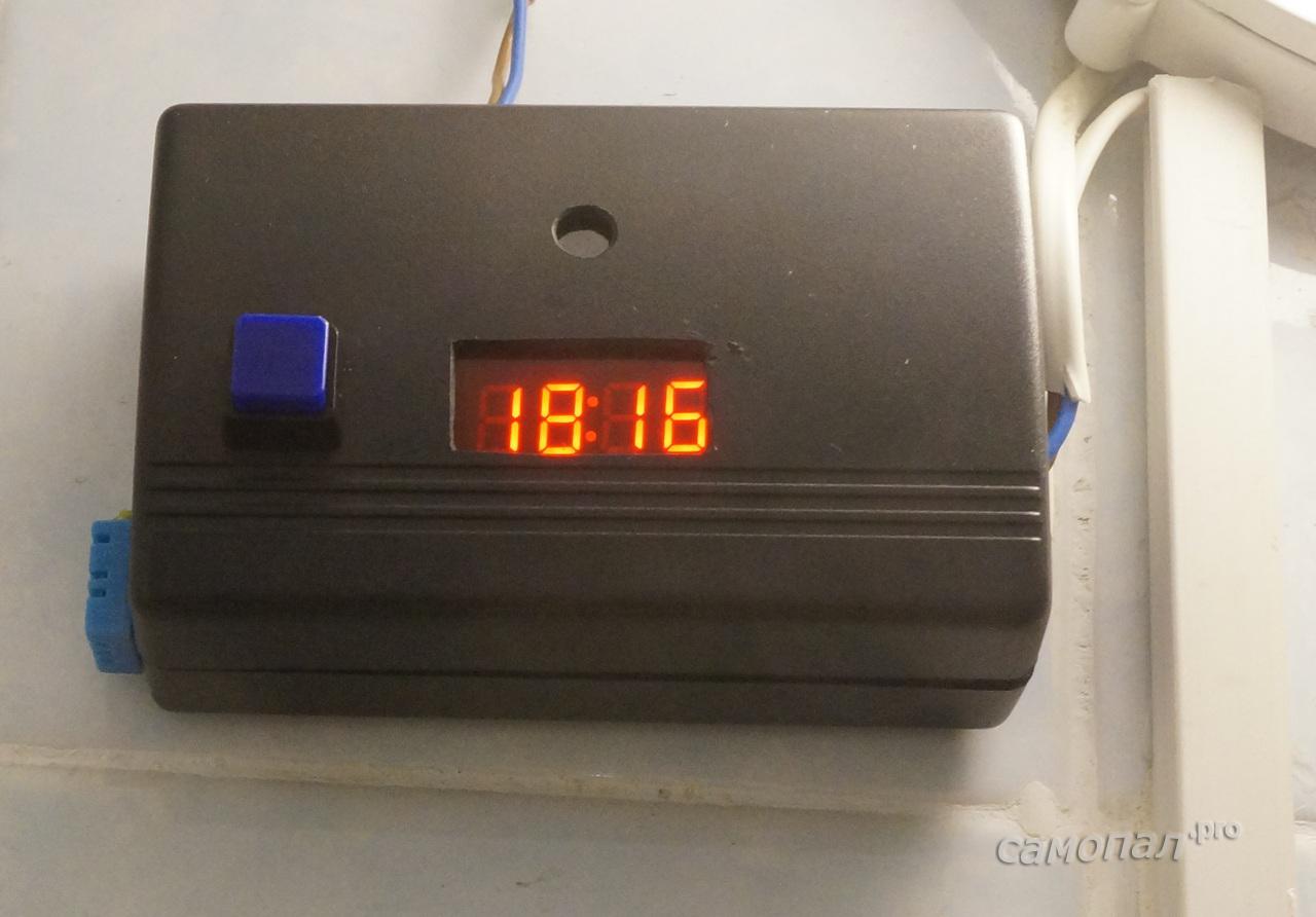
- Well, since there’s still the Internet, time display with synchronization via the NTP protocol.
All these functions make it possible to analyze the operation of the controller and, in the future, optimize the parameters of the control algorithm. Well, this controller will go into the general system of a smart home with monitoring the environmental parameters of the bathroom.
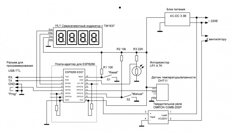
The scheme has not changed much from the previous version:
- Atmega328 replaced by ESP8266
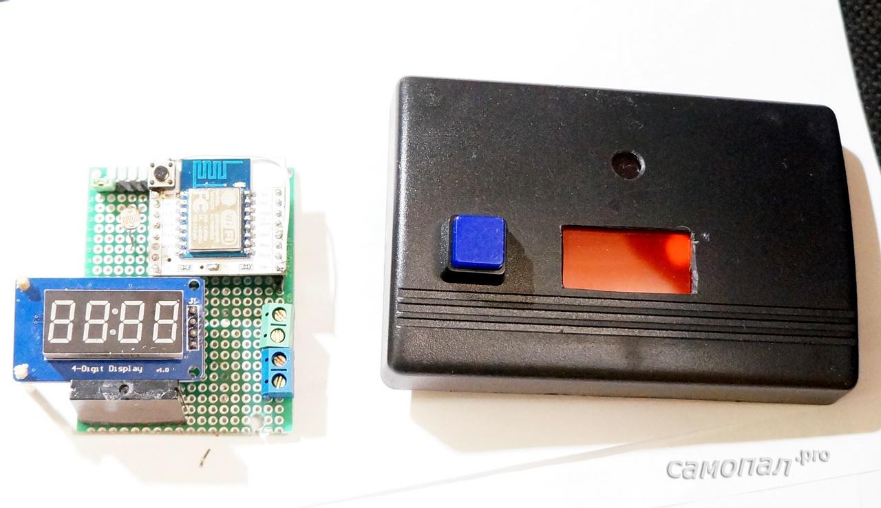
- Seven-segment indicator replaced the finished display module with TN1637
- A triac with an optocoupler is replaced by a solid-state relay (the same, but in the case).
All the main differences in the controller program.
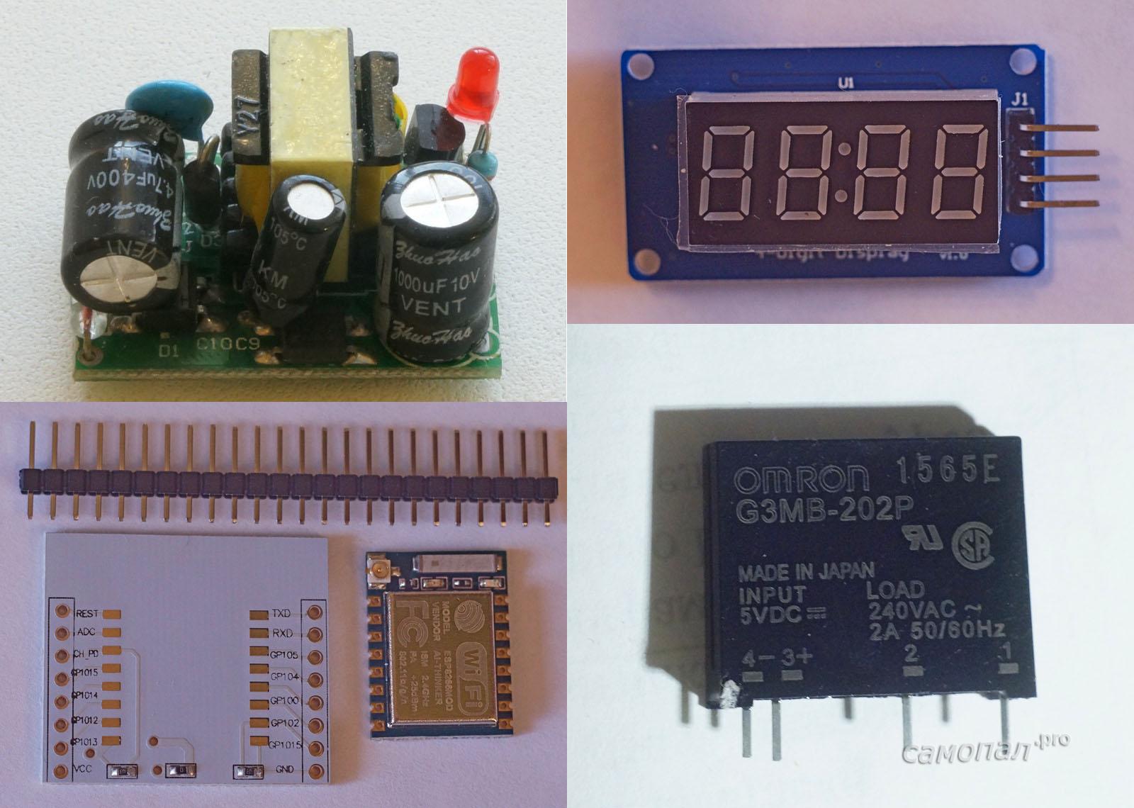
List of components
- ESP8266 ESP07 module with adapter board ~ $ 2.3
- Four-digit seven-segment display on the TM1637 chip with I2C connection ~ $ 1
- Solid State Relay OMRON G3MB-202P ~ $ 1
- Power Supply 220V / 3.3V 600mA ~ $ 2.2
- Temperature and humidity sensor (accuracy is low, but sufficient for my tasks) DHT11 ~ $ 0.7
- Instrument plastic case 110x73x34 ~ $ 1
- Photoresistor, just resistors, breadboard and wires
Total about $ 9
All parts except the case and the power supply were bought on aliexpress.com. I order cases and power supplies at reasonable prices from taobao.com
Controller assembly
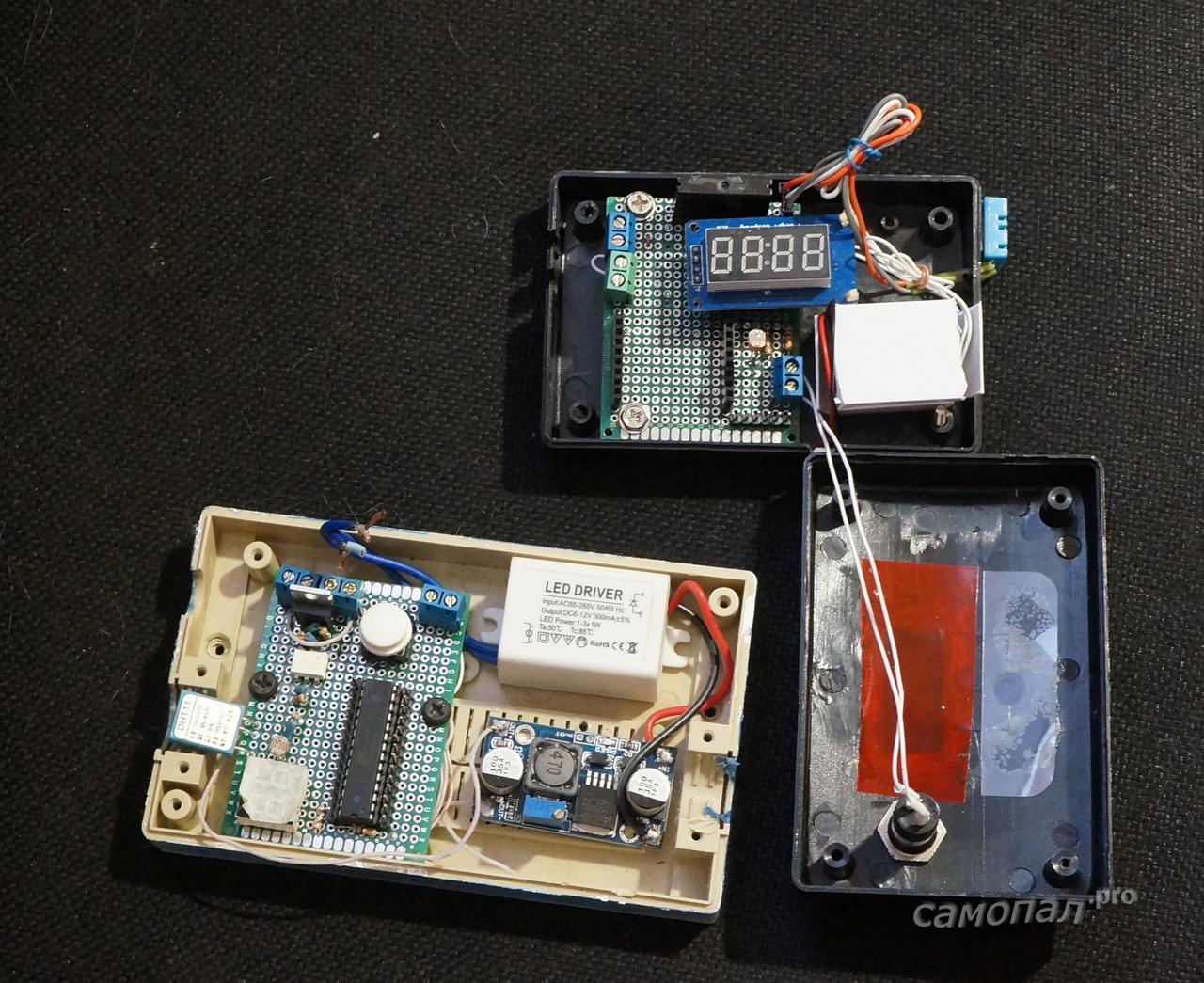
This controller is a prototype for future devices on the ESP8266, so the installation was done on a breadboard.
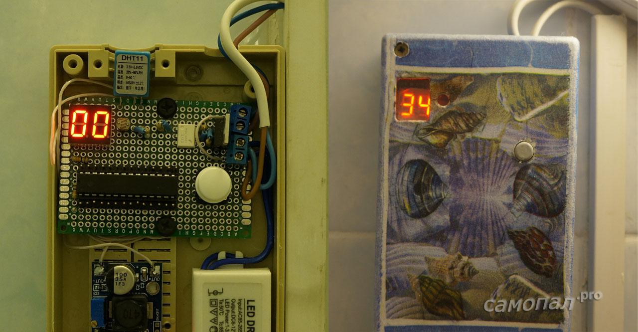
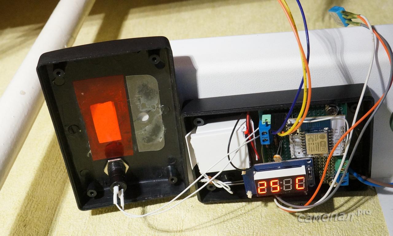
I make a light filter under the indicator from a folder-corner for papers purchased in a stationery store. A transparent window for the photoresistor - a protective film left over from some phone (I ordered it once with a margin, now it’s lying around).
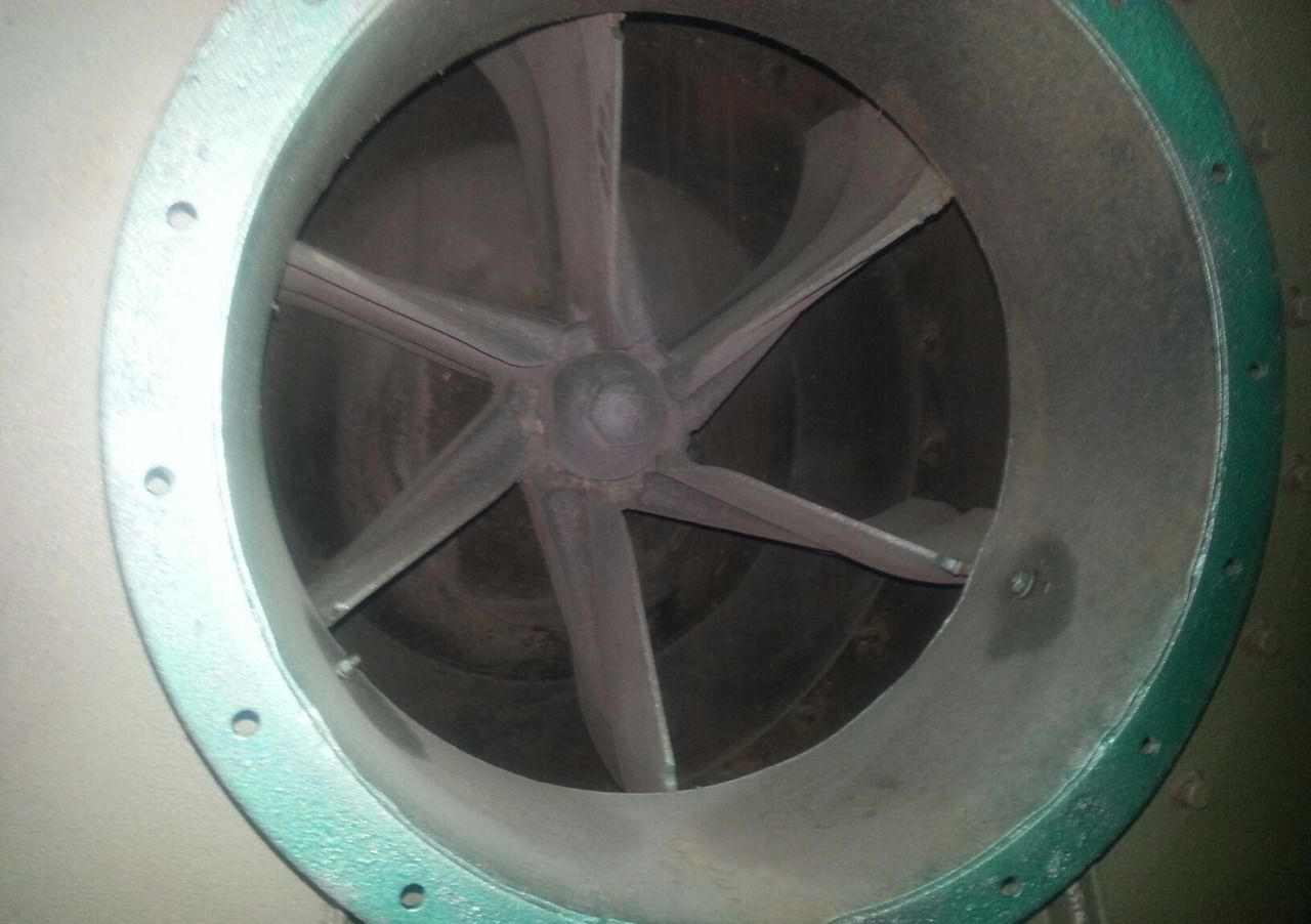
And this is my old controller that worked in the bathroom for two years.
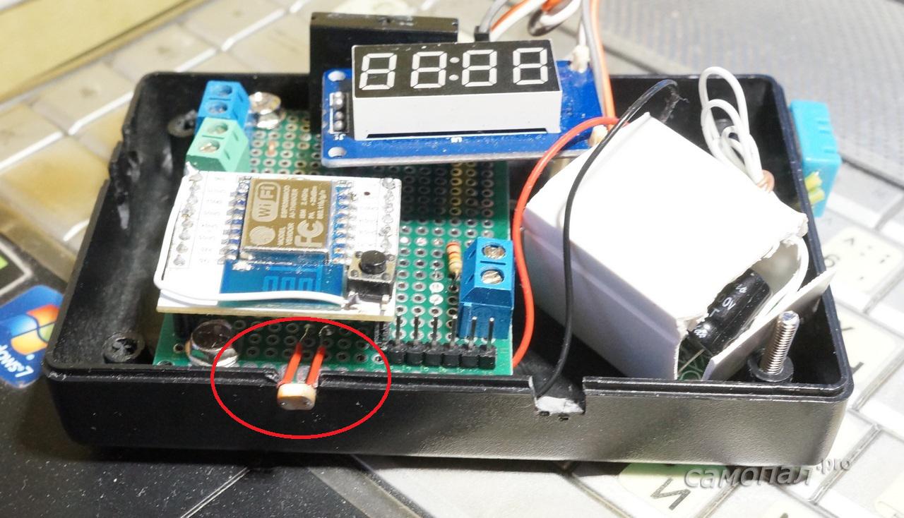
When debugging, a technological defect was detected - the photodiode behind the window in the case received too little light and without an amplifier it didn’t work when the lamp was ignited in the bathroom, I had to bring it out towards the lamp
Now I’ll tell you about the features of the program, control algorithms and settings of this controller.
ESP8266, unlike Atmega328, on which the previous version was implemented, has much more memory (RAM, ROM. EEPROM), which, together with the built-in WiFi, allows you to implement the functions of the built-in WEB server without saving memory for text strings.
But with the GPIO, the ESP8266 is pretty bad, therefore, such a luxury as managing a seven-segment indicator is not directly accessible to it. Therefore, the indicator on the TM1637 chip was selected, which requires only two outputs for connection.
Development environment
I have played enough with various ESP8266 firmwares that allow me to write programs on the built-in interpreters LUA, JC and generally program through WEB. I tried to write on one SDK. He settled on a compromise option - programming in the Arduino IDE.
A fairly simple installation, programming, and a huge number of ready-made libraries, which, for the most part, work on the ESP. This environment allowed the use of a lot of old code that provides the basic logic for the operation of the fan control controller, which was preserved from the previous version.
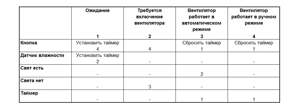
Basically, it was interesting to transfer a well-proven algorithm that implements a finite deterministic state machine described in the state transition table:
Arduino libraries came up without problemsDHT for working with humidity / temperature sensors from Adafruit and for working with the indicator on the TM1637 DigitalTube .
The details of using the Arduino IDE to program the ESP8266 are well described in this article.
Implementing New Features
It is very inconvenient to make WiFi controllers in which the network connection parameters are stitched. Imagine what the change of access point name or password will result in if there are a dozen of such controllers at home?
Therefore, this program implements the functions of storing connection parameters in non-volatile EEPROM memory and their configuration via the network. The structure for saving the parameters, as well as reading and writing it, are implemented in the WC_EEPROM.h and WC_EEPROM.cpp files of my project. Verification of reading and writing is done by calculating the checksum of the configuration and comparing it with the one written in the EEPROM.
In addition to the network configuration, all timeouts and other parameters of the fan control algorithm are also saved in memory, which allows optimizing and tuning this controller directly “over the air”.
Display of operating modes, controller configuration, as well as direct fan control is implemented using the built-in WEB server (WC_HTTP.h and WC_НTTP.cpp files)
The access point configuration algorithm is as follows:
If the ESP-cabinet could not connect to the access point specified in the EEPROM configuration , then it raises its access point and at 192.168.4.1, allows you to configure.
Well, if connected, it works as usual.
The main page of the WEB server shows the basic parameters of the controller and allows you to manually turn on / off the controller (analogue of pressing the manual control button)

Here you can also go to the network settings

page and the settings page of the controller operation algorithm
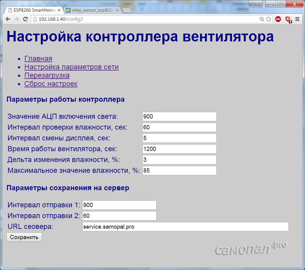
From these two pages, you can reboot the controller and reset all the “default” settings.
I am planning to bring beauty to the interface in the future, when the concept of a smart home on WiFi is more or less settled down in my head.
Another function implemented in this program is a real-time clock synchronized via the NTP protocol on the Internet. (Files WC_NTP.h and WC_NTP.cpp)
I will not describe the main algorithm, the logic of work has worked well and remains the same, you can read about it in the previous article. Major changes have affected the display. I want to draw attention to one “feature” - the DisplaySpecialChar () function, which allows you to display any character that you can think of for displaying on a seven-segment indicator using a bitmask. I came up with this “percent” symbol in the humidity display
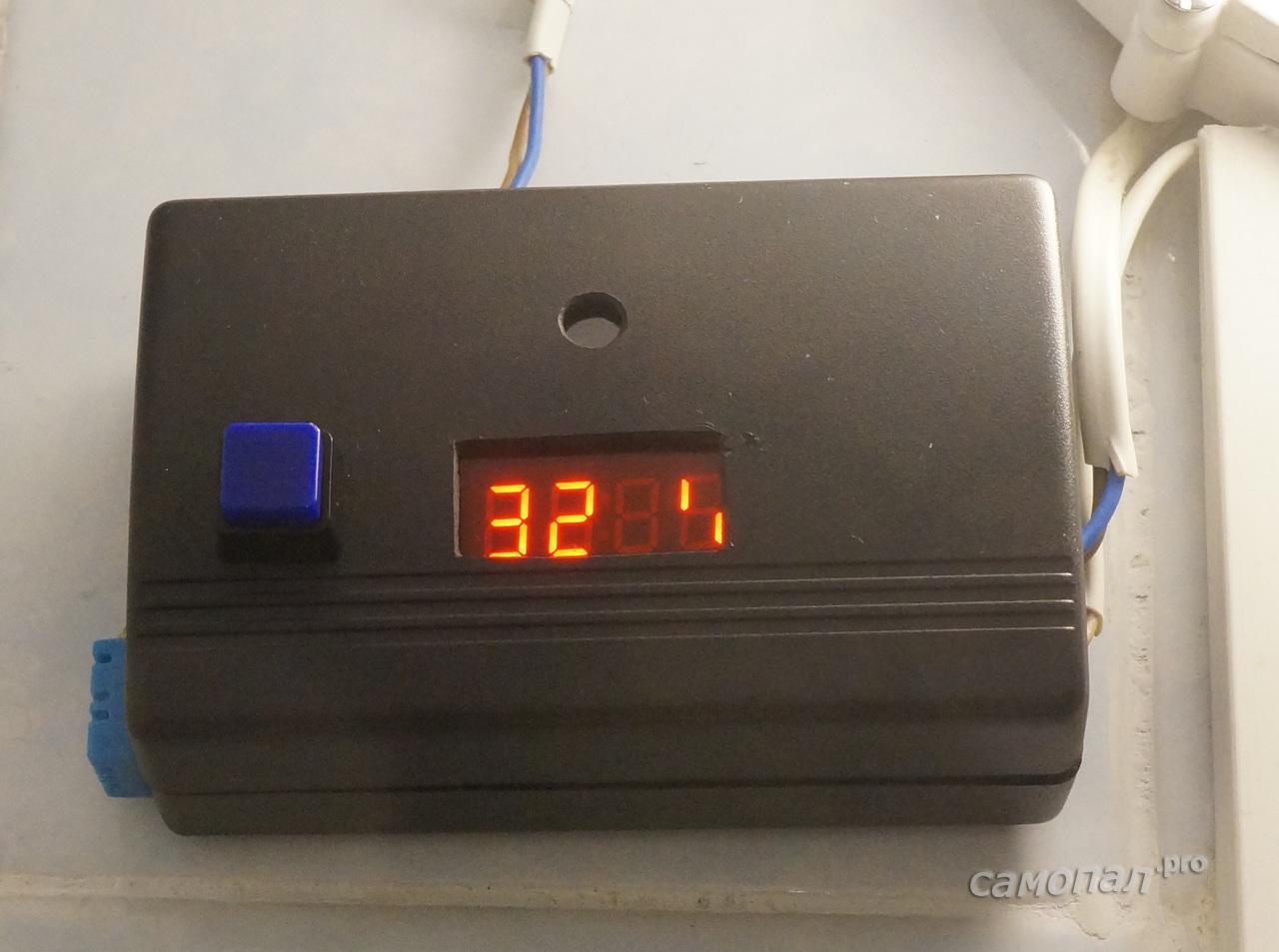
and the “degree” symbol in the temperature display. The
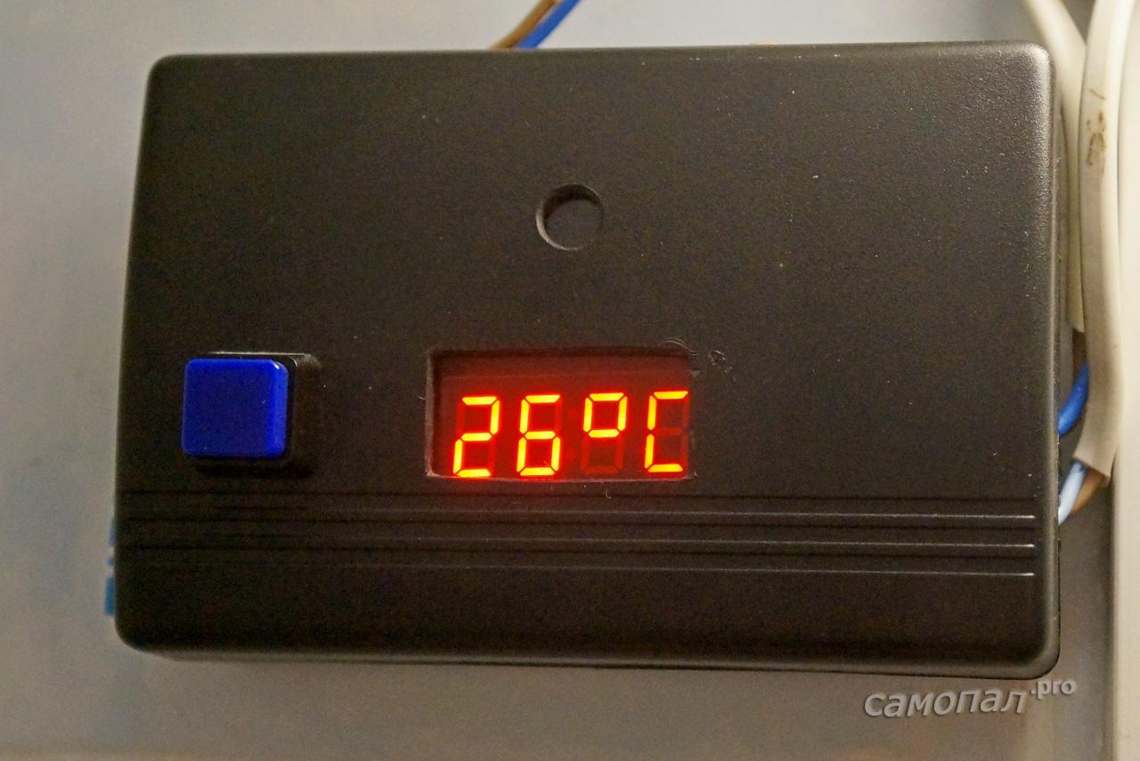
bits in the bitmask correspond to the indicator segments.
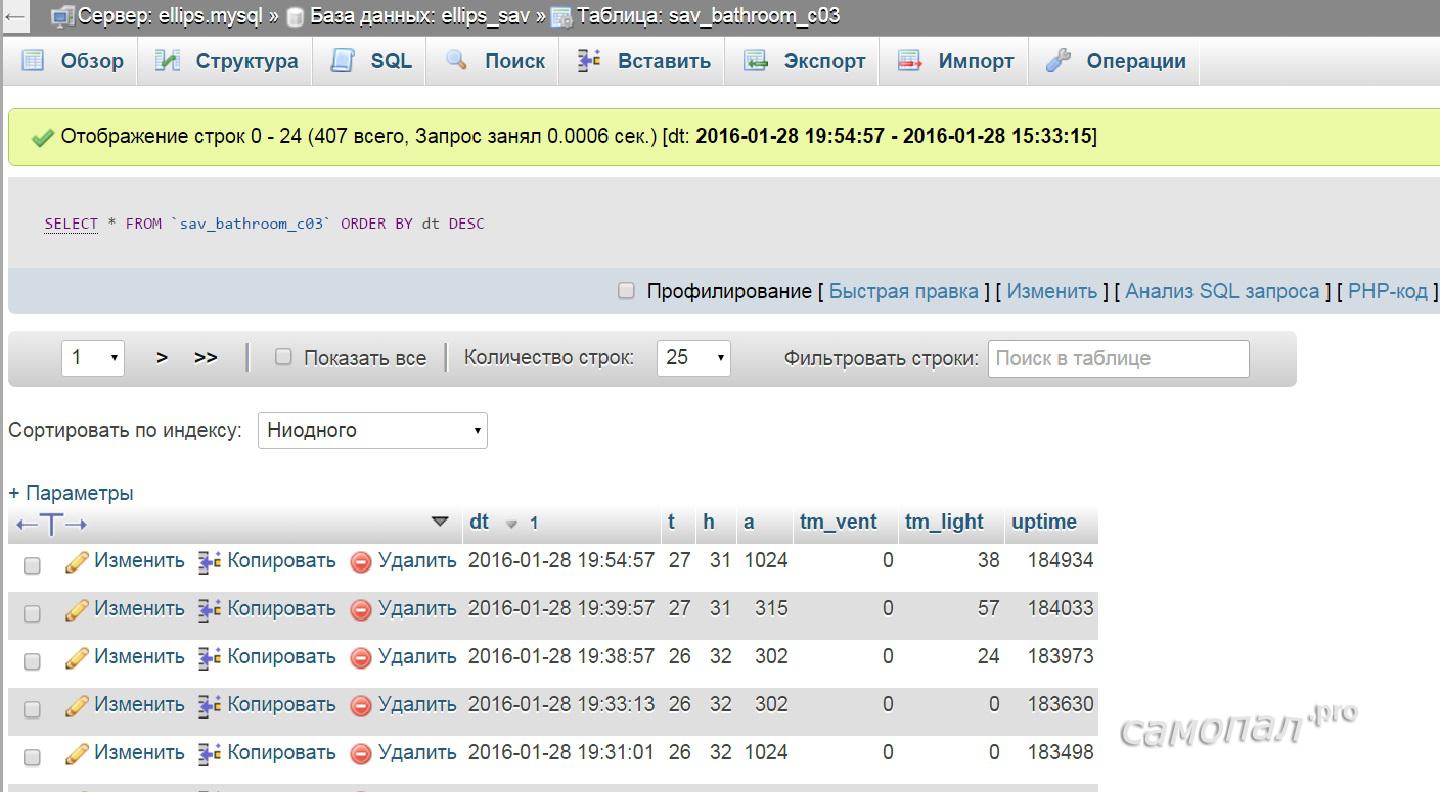
Well, the last of the new functions is saving parameters to a server on the Internet for display and subsequent analysis. The values of humidity, temperature, an analog port with a photoresistor for adjusting the threshold for lighting, the time of the fan, the time of burning the light and the UPTIME-time of the controller from the last reboot are saved.
Recording to the server occurs in two modes. With greater frequency, parameters are recorded when “something happens” in the bathroom, at which time either the light is on or the fan is working. All timeouts are configured via the WEB interface.
Data is saved to my server on the Internet. The server address can be configured, but the recording format is still sewn into the program. Again, until better times ustananivaniya concept))). Now the parameters are saved by the simplest PHP script to a table with a simple structure.
It’s quite simple to reconfigure the saving settings to the same “popular monitoring”. Personally, this server does not suit me with restrictions on the frequency of data storage and the depth of the archive.
Optimize controller settings
After the "trial operation", you can determine whether the thresholds for lighting and humidity, as well as timeouts for various events, are set correctly. In the previous implementation, I set the response time to 20 minutes, sitting in the bathroom with a stopwatch. After observing the graph of parameters during several showerings, I saw the following:
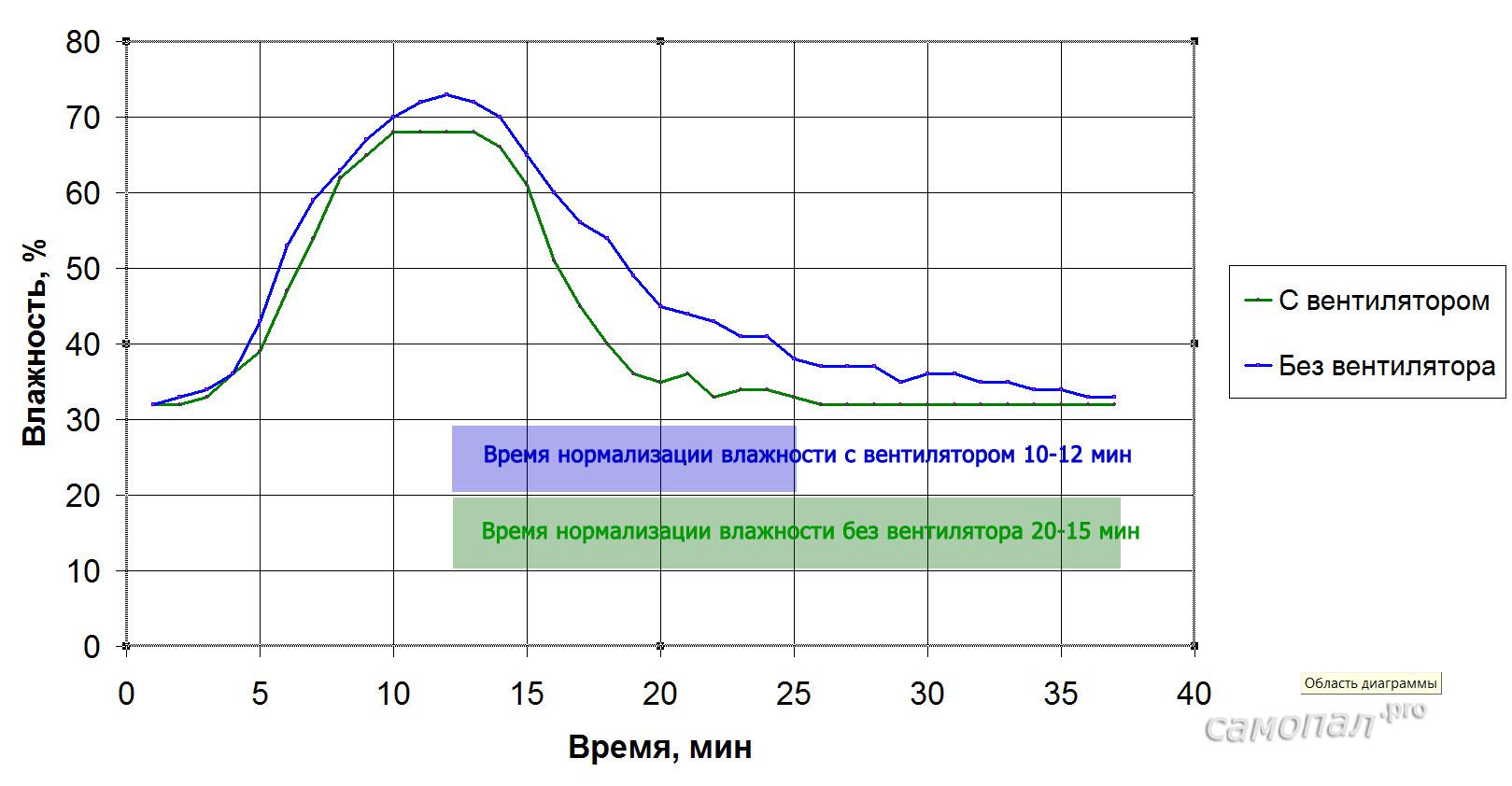
- Humidity in the winter changes by 35-40%
- Humidity normalization time with natural ventilation 20-25 minutes
- Humidity normalization time with a working fan 10-12 min
- The fan doubles the ventilation efficiency
Based on this, you can safely reduce the fan operating time to 12 minutes, thereby extending its service life and saving a little energy. A similar analysis can be done for other seasons, when the humidity in the apartment is completely different.
Now, after analysis, you can increase the period of writing parameters to the server.
conclusions
- The controller on the ESP8266 is stable, it performs its functions.
- Its functionality has expanded, now it is easy to manage and it integrates normally into the Smart Home system
- Some things need to be improved, for example, the WEB interface, access authorization, the server part and some inaccuracies in calculating the fan and light hours. May be revealed and other Wishlist for improvement.
- The pilot project for Smart Home on WiFi can be considered successful;)
The sketch can be downloaded here. I would be very grateful if you report any bugs.
Sketch of the fan controller on WiFi The
time spent on the project is two days off
PS I immediately answer the question, why is it so difficult? Can I put in parallel to the switch or on the timer?
- Yes, you can. But the inclusion of timer and light did not suit me. In addition, it is a hobby, the implementation of some ideas that are used in other projects.
The storage facility was buggy again, so the pictures from my blog . There you can see about my developments in smart home