Interference in global navigation satellite systems. Continuation
To my surprise, the previous article was warmly received. Today we continue consideration of this issue.

Anti-jamming measures
In navigation, the noise level always exceeds the signal level. To determine the level of interference (interference / signal ratio, J / S ratio), it is considered how much the noise exceeds the noise level. The following are methods for increasing the noise immunity of receivers, together with the maximum interference against which these methods are effective.

1. The increase in signal bandwidth (up to 10 dB);
2. Increase in transmitter power on the spacecraft (up to 20 dB);
3. Integration of navigation receivers (up to 30 dB);
4. The use of digital hardware filters (up to 40 dB);
5. The use of time-frequency correction (up to 50 dB);
6. Use of antenna methods (up to 70 dB);
The first two methods depend on the signal used by the spacecraft and cannot be changed from Earth after launch. Antenna methods greatly complicate and increase the cost of consumer equipment, which drastically reduces the possible range of users.

Integration of navigation receivers does not significantly increase the noise immunity of the navigation receiver. This is due to the fact that inertial navigation systems (ANNs) are not affected by radio interference and have high measurement accuracy in the short term. However, the error in determining the navigation parameters accumulates over time and requires correction from GNSS. The above diagram shows where, using the Kalman filter, the navigation receiver is integrated.
The use of time-frequency correction (suppression of interference in the frequency domain) is an effective method, but it is very difficult to implement in real time. This is because the execution of this method should be carried out using a microcomputer in parallel with the operation of tracking loops, discriminators, solving navigation and speed problems and resolving ambiguities when working in RTK mode. Based on this, in order to be able to suppress interference in the frequency domain, it is necessary to have a significant reserve of computing power that will not be involved in the absence of interference.
Two categories are distinguished among digital filters:
1. Recursive filters (with infinite impulse response);
2. Non-recursive filters (with finite impulse response).
What to choose?
The question of choice is highly dependent on the available hardware. Optimal in terms of complexity of implementation and cost of the end device are digital filters. In the navigation receivers you can find both IIR and FIR filters. FIR filters have the advantage of being able to create a filter with a linear phase response and, as a result, a constant group delay. This means that different frequency components will be delayed by the same number of clock cycles when passing through the filter. However, using an IIR filter, a much narrower notch window and a generally smaller transition band can be achieved with the same filter order.
How does it work?
For interference suppression algorithms to work, information about the interference environment is needed. The detection of narrow-band interference is conveniently performed in the frequency domain, while the behavior of pseudo-delays, energy potential, and Doppler bias for the presence of jumps should be analyzed to detect spoofing attacks.

To detect interference, window functions should be used in connection with the so-called spectrum spreading phenomenon. Due to the fact that jammers can be located at different distances from the receiver, interference will have different levels. Without the use of window functions, some interference may be masked by the side lobes of a rectangular window, not detected and not compensated.
A few words about my development

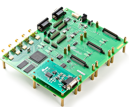
My task was to develop a suppressor in the existing structure of the navigation receiver based on the VLSI 1879VIA1Ya manufactured by the Scientific and Technical Center "Module". If we briefly talk about this hardware and software platform, we can distinguish:
1. 4 12-bit ADCs with a sampling frequency of 81.92 MHz;
2. The core of ARM1176;
3. 2 NeuroMatrix DSP cores with a vector-matrix multiplier capable of successfully parallelizing operations with low-bit values;
4. Hardware signal preprocessing unit (BPOS).

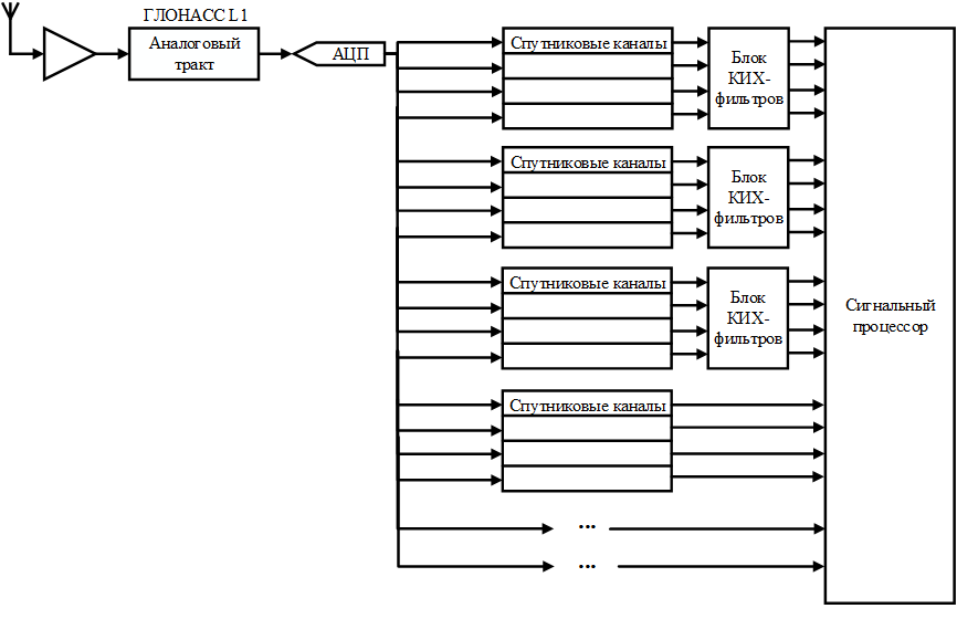
The rest of the details can be found on the site, now we will pay more attention to BPOS. The general receiver circuit is given above. It contains an antenna, an analog path (for example, GLONASS L1, but now it does not matter), an ADC, digital channels and a signal processor. BPOS contains 24 digital channels, 12 of which have access to three blocks of FIR filters. Each block contains 4 64th order FIR filters with 8-bit coefficients. Inside one unit, filters can be switched in series or in parallel to implement from one to four suppressors. Digital channels contain a digital local oscillator, low-pass filter, a decimator (for lowering the sampling frequency), as well as a normalizer. In the signal processor (NeuroMatrix, not ARM), the algorithms for detecting interference, calculating the coefficients of hardware filters,
Using a 128th-order filter with 16-bit coefficients, the receiver was able to achieve operability under the influence of a narrow-band interference with a power of 67 dB located in the main lobe of the signal spectrum.
I will be happy to answer questions in the comments, or, if there are a significant number, I will write the third part of the article. Thank you for your attention.
A small update. I
completely forgot to bring two of the most interesting pictures. The following is the spectrum of the navigation signal in the presence of narrow-band interference before and after passing through the developed filter:

As well as the output of the matched filter for these spectra:

As you can see, in the presence of narrow-band interference, the correlation peak cannot be distinguished in the correlator output.
It should also be noted that the filter has a feature, namely the insertion group delay equal to half the size of the filter. This value is taken into account in the subsequent solution of the navigation problem and, thereby, is fully compensated.

Anti-jamming measures
In navigation, the noise level always exceeds the signal level. To determine the level of interference (interference / signal ratio, J / S ratio), it is considered how much the noise exceeds the noise level. The following are methods for increasing the noise immunity of receivers, together with the maximum interference against which these methods are effective.

1. The increase in signal bandwidth (up to 10 dB);
2. Increase in transmitter power on the spacecraft (up to 20 dB);
3. Integration of navigation receivers (up to 30 dB);
4. The use of digital hardware filters (up to 40 dB);
5. The use of time-frequency correction (up to 50 dB);
6. Use of antenna methods (up to 70 dB);
The first two methods depend on the signal used by the spacecraft and cannot be changed from Earth after launch. Antenna methods greatly complicate and increase the cost of consumer equipment, which drastically reduces the possible range of users.

Integration of navigation receivers does not significantly increase the noise immunity of the navigation receiver. This is due to the fact that inertial navigation systems (ANNs) are not affected by radio interference and have high measurement accuracy in the short term. However, the error in determining the navigation parameters accumulates over time and requires correction from GNSS. The above diagram shows where, using the Kalman filter, the navigation receiver is integrated.
The use of time-frequency correction (suppression of interference in the frequency domain) is an effective method, but it is very difficult to implement in real time. This is because the execution of this method should be carried out using a microcomputer in parallel with the operation of tracking loops, discriminators, solving navigation and speed problems and resolving ambiguities when working in RTK mode. Based on this, in order to be able to suppress interference in the frequency domain, it is necessary to have a significant reserve of computing power that will not be involved in the absence of interference.
Two categories are distinguished among digital filters:
1. Recursive filters (with infinite impulse response);
2. Non-recursive filters (with finite impulse response).
What to choose?
The question of choice is highly dependent on the available hardware. Optimal in terms of complexity of implementation and cost of the end device are digital filters. In the navigation receivers you can find both IIR and FIR filters. FIR filters have the advantage of being able to create a filter with a linear phase response and, as a result, a constant group delay. This means that different frequency components will be delayed by the same number of clock cycles when passing through the filter. However, using an IIR filter, a much narrower notch window and a generally smaller transition band can be achieved with the same filter order.
How does it work?
For interference suppression algorithms to work, information about the interference environment is needed. The detection of narrow-band interference is conveniently performed in the frequency domain, while the behavior of pseudo-delays, energy potential, and Doppler bias for the presence of jumps should be analyzed to detect spoofing attacks.

To detect interference, window functions should be used in connection with the so-called spectrum spreading phenomenon. Due to the fact that jammers can be located at different distances from the receiver, interference will have different levels. Without the use of window functions, some interference may be masked by the side lobes of a rectangular window, not detected and not compensated.
A few words about my development

My task was to develop a suppressor in the existing structure of the navigation receiver based on the VLSI 1879VIA1Ya manufactured by the Scientific and Technical Center "Module". If we briefly talk about this hardware and software platform, we can distinguish:
1. 4 12-bit ADCs with a sampling frequency of 81.92 MHz;
2. The core of ARM1176;
3. 2 NeuroMatrix DSP cores with a vector-matrix multiplier capable of successfully parallelizing operations with low-bit values;
4. Hardware signal preprocessing unit (BPOS).

The rest of the details can be found on the site, now we will pay more attention to BPOS. The general receiver circuit is given above. It contains an antenna, an analog path (for example, GLONASS L1, but now it does not matter), an ADC, digital channels and a signal processor. BPOS contains 24 digital channels, 12 of which have access to three blocks of FIR filters. Each block contains 4 64th order FIR filters with 8-bit coefficients. Inside one unit, filters can be switched in series or in parallel to implement from one to four suppressors. Digital channels contain a digital local oscillator, low-pass filter, a decimator (for lowering the sampling frequency), as well as a normalizer. In the signal processor (NeuroMatrix, not ARM), the algorithms for detecting interference, calculating the coefficients of hardware filters,
Using a 128th-order filter with 16-bit coefficients, the receiver was able to achieve operability under the influence of a narrow-band interference with a power of 67 dB located in the main lobe of the signal spectrum.
I will be happy to answer questions in the comments, or, if there are a significant number, I will write the third part of the article. Thank you for your attention.
A small update. I
completely forgot to bring two of the most interesting pictures. The following is the spectrum of the navigation signal in the presence of narrow-band interference before and after passing through the developed filter:

As well as the output of the matched filter for these spectra:

As you can see, in the presence of narrow-band interference, the correlation peak cannot be distinguished in the correlator output.
It should also be noted that the filter has a feature, namely the insertion group delay equal to half the size of the filter. This value is taken into account in the subsequent solution of the navigation problem and, thereby, is fully compensated.
