Simple battery capacity tester on Arduino
Recently, I began to notice that my smartphone began to discharge faster. The search for the software “eater” did not bring fruit energy, so I began to wonder if it was time to replace the battery. But there was no absolute certainty that there was no reason for the battery. Therefore, before ordering a new battery, I decided to try to measure the real capacity of the old one. To do this, it was decided to assemble a simple battery capacity meter, especially since this idea was hatched for a long time - there are so many batteries and accumulators surrounding us in everyday life, and it would be nice to have the opportunity to test them from time to time.
The very idea underlying the operation of the device is extremely simple: there is a charged battery and a load in the form of a resistor, you only need to measure the current, voltage and time during the discharge of the battery, and according to the data obtained, calculate its capacity. In principle, you can do with a voltmeter and ammeter, but sitting at the devices for several hours is a dubious pleasure, so it is much easier and more accurate to do this using the data logger. I used the Arduino Uno platform as such a registrar.
1. Scheme
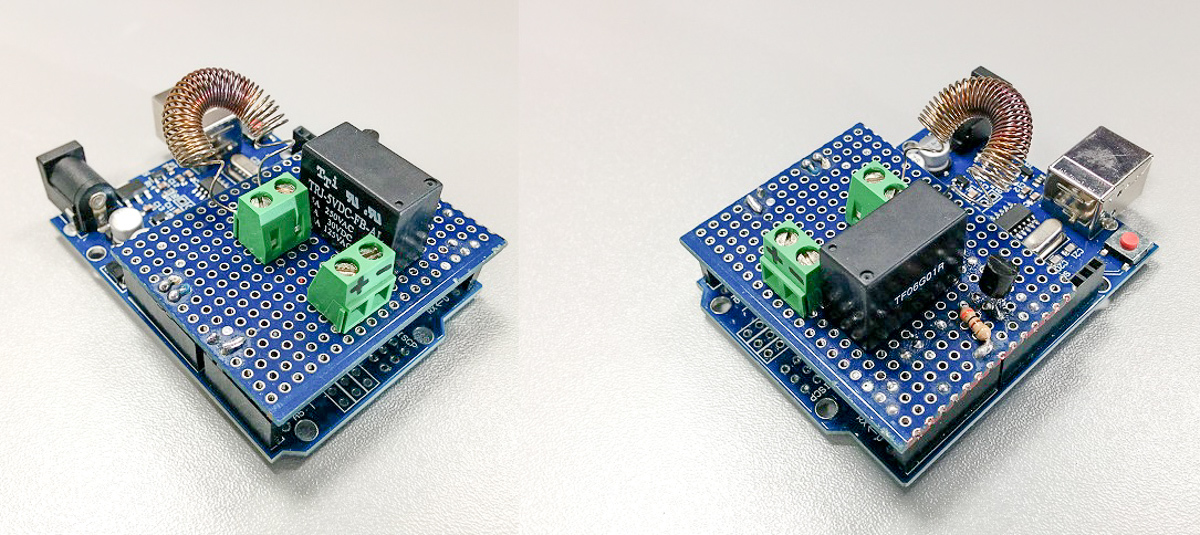
There are no problems with measuring voltage and time in Arduino - there is an ADC, but you need a shunt to measure current. I got an idea to use the load resistor itself as a shunt. That is, knowing the voltage on it and having previously measured the resistance, we can always calculate the current. Therefore, the simplest version of the circuit will consist only of a load and a battery, with a connection to the analog input of Arduino. But it would be nice to provide for a load shedding upon reaching the threshold voltage on the battery (for Li-Ion, this is usually 2.5-3V). Therefore, I provided in the circuit a relay controlled by digital pin 7 through a transistor. The final version of the circuit in the figure below.

I placed all the elements of the circuit on a piece of the breadboard, which is installed directly on Uno. As a load, I used a 0.5 mm thick nichrome wire spiral with a resistance of about 3 ohms. This gives a calculated value of the discharge current of 0.9-1.2A.
2. Current measurement
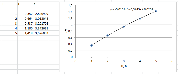
As mentioned above, the current is calculated based on the voltage on the coil and its resistance. But it is worth considering that the spiral heats up, and the resistance of nichrome is pretty much dependent on temperature. To compensate for the error, I simply took the volt-ampere characteristic of the spiral using a laboratory power supply and letting it warm up before each measurement. Next, I derived the equation of the trend line in Excel (the graph below), which gives a fairly accurate dependence of i (u) taking into account heating. It can be seen that the line is not straight.
3. Voltage measurement
Since the accuracy of this tester directly depends on the accuracy of voltage measurement, I decided to pay special attention to this. Other articles have repeatedly mentioned the method that allows you to measure voltage most accurately with Atmega controllers. I will repeat only briefly - the essence is to determine the internal reference voltage by the means of the controller itself. I used the materials in this article.
4. The
Code program is nothing complicated:
Every 5 seconds, data on time, battery voltage, discharge current, current capacity in mAh and Wh, as well as supply voltage are transmitted to the serial port. The current is calculated by the function obtained in paragraph 2. When the threshold voltage Voff is reached, the test is terminated.
The only, in my opinion, interesting point in the code I would single out is the use of a digital filter. The fact is that when reading the voltage, the values inevitably “dance” up and down. At first I tried to reduce this effect by simply taking 100 measurements in 5 seconds and taking the average. But the result still did not satisfy me. During the search, I came across suchsoftware filter. It works in a similar way, but instead of averaging, it sorts all 100 measurement values in ascending order, selects the central 10 and calculates the average of them. The result impressed me - the measurement fluctuations completely stopped. I decided to use it to measure the internal reference voltage (readVcc function in the code).
5. Results The
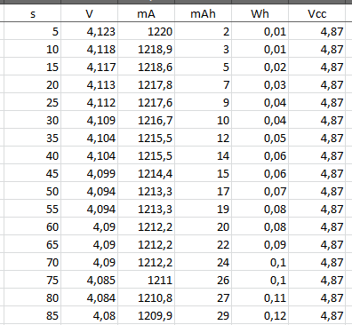
data from the serial port monitor is imported into Excel in a few clicks and looks as follows:
Next, it is easy to build a battery discharge graph:
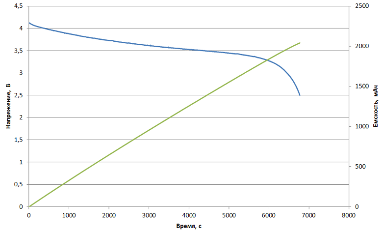
In the case of my Nexus 5, the declared BL-T9 battery capacity is 2300 mAh. Measured by me - 2040 mAh with a discharge of up to 2.5 V. In reality, the controller hardly allows the battery to sit up to such a low voltage, most likely a threshold value of 3V. The capacity in this case is 1960 mAh. A year and a half of telephone service led to a drawdown of approximately 15% in capacity. With the purchase of a new battery, it was decided to postpone.
With the help of this tester, several other Li-Ion batteries have already been discharged. The results look very realistic. The measured capacity of the new batteries is the same as declared with a deviation of less than 2%.
This tester is also suitable for metal hydride finger batteries. The discharge current in this case will be about 400 mA.
The very idea underlying the operation of the device is extremely simple: there is a charged battery and a load in the form of a resistor, you only need to measure the current, voltage and time during the discharge of the battery, and according to the data obtained, calculate its capacity. In principle, you can do with a voltmeter and ammeter, but sitting at the devices for several hours is a dubious pleasure, so it is much easier and more accurate to do this using the data logger. I used the Arduino Uno platform as such a registrar.
1. Scheme
There are no problems with measuring voltage and time in Arduino - there is an ADC, but you need a shunt to measure current. I got an idea to use the load resistor itself as a shunt. That is, knowing the voltage on it and having previously measured the resistance, we can always calculate the current. Therefore, the simplest version of the circuit will consist only of a load and a battery, with a connection to the analog input of Arduino. But it would be nice to provide for a load shedding upon reaching the threshold voltage on the battery (for Li-Ion, this is usually 2.5-3V). Therefore, I provided in the circuit a relay controlled by digital pin 7 through a transistor. The final version of the circuit in the figure below.
I placed all the elements of the circuit on a piece of the breadboard, which is installed directly on Uno. As a load, I used a 0.5 mm thick nichrome wire spiral with a resistance of about 3 ohms. This gives a calculated value of the discharge current of 0.9-1.2A.
2. Current measurement
As mentioned above, the current is calculated based on the voltage on the coil and its resistance. But it is worth considering that the spiral heats up, and the resistance of nichrome is pretty much dependent on temperature. To compensate for the error, I simply took the volt-ampere characteristic of the spiral using a laboratory power supply and letting it warm up before each measurement. Next, I derived the equation of the trend line in Excel (the graph below), which gives a fairly accurate dependence of i (u) taking into account heating. It can be seen that the line is not straight.
3. Voltage measurement
Since the accuracy of this tester directly depends on the accuracy of voltage measurement, I decided to pay special attention to this. Other articles have repeatedly mentioned the method that allows you to measure voltage most accurately with Atmega controllers. I will repeat only briefly - the essence is to determine the internal reference voltage by the means of the controller itself. I used the materials in this article.
4. The
Code program is nothing complicated:
Program text
#define A_PIN 1
#define NUM_READS 100
#define pinRelay 7
const float typVbg = 1.095; // 1.0 -- 1.2
float Voff = 2.5; // напряжение выключения
float I;
float cap = 0;
float V;
float Vcc;
float Wh = 0;
unsigned long prevMillis;
unsigned long testStart;
void setup() {
  Serial.begin(9600);
  pinMode(pinRelay, OUTPUT);
  Serial.println("Press any key to start the test...");
  while (Serial.available() == 0) {
  }
  Serial.println("Test is launched...");
  Serial.print("s");
  Serial.print(" ");
  Serial.print("V");
  Serial.print(" ");
  Serial.print("mA");
  Serial.print(" ");
  Serial.print("mAh");
  Serial.print(" ");
  Serial.print("Wh");
  Serial.print(" ");
  Serial.println("Vcc");
  digitalWrite(pinRelay, HIGH);
  testStart = millis();
  prevMillis = millis();
}
void loop() {
  Vcc = readVcc(); //считывание опорного напряжения
  V = (readAnalog(A_PIN) * Vcc) / 1023.000; //считывание напряжения АКБ
  if (V > 0.01) I = -13.1 * V * V + 344.3 * V + 23.2; //расчет тока по ВАХ спирали
  else I=0;
  cap += (I * (millis() - prevMillis) / 3600000); //расчет емкости АКБ в мАч
  Wh += I * V * (millis() - prevMillis) / 3600000000; //расчет емкости АКБ в ВтЧ
  prevMillis = millis();
  sendData(); // отправка данных в последовательный порт
  if (V < Voff) { //выключение нагрузки при достижении порогового напряжения
    digitalWrite(pinRelay, LOW);
    Serial.println("Test is done");
    while (2 > 1) {
    }
  }
}
void sendData() {
  Serial.print((millis() - testStart) / 1000);
  Serial.print(" ");
  Serial.print(V, 3);
  Serial.print(" ");
  Serial.print(I, 1);
  Serial.print(" ");
  Serial.print(cap, 0);
  Serial.print(" ");
  Serial.print(Wh, 2);
  Serial.print(" ");
  Serial.println(Vcc, 3);
}
float readAnalog(int pin) {
  // read multiple values and sort them to take the mode
  int sortedValues[NUM_READS];
  for (int i = 0; i < NUM_READS; i++) {
    delay(25);
    int value = analogRead(pin);
    int j;
    if (value < sortedValues[0] || i == 0) {
      j = 0; //insert at first position
    }
    else {
      for (j = 1; j < i; j++) {
        if (sortedValues[j - 1] <= value && sortedValues[j] >= value) {
          // j is insert position
          break;
        }
      }
    }
    for (int k = i; k > j; k--) {
      // move all values higher than current reading up one position
      sortedValues[k] = sortedValues[k - 1];
    }
    sortedValues[j] = value; //insert current reading
  }
  //return scaled mode of 10 values
  float returnval = 0;
  for (int i = NUM_READS / 2 - 5; i < (NUM_READS / 2 + 5); i++) {
    returnval += sortedValues[i];
  }
  return returnval / 10;
}
float readVcc() {
  // read multiple values and sort them to take the mode
  float sortedValues[NUM_READS];
  for (int i = 0; i < NUM_READS; i++) {
    float tmp = 0.0;
    ADMUX = _BV(REFS0) | _BV(MUX3) | _BV(MUX2) | _BV(MUX1);
    ADCSRA |= _BV(ADSC); // Start conversion
    delay(25);
    while (bit_is_set(ADCSRA, ADSC)); // measuring
    uint8_t low = ADCL; // must read ADCL first - it then locks ADCH
    uint8_t high = ADCH; // unlocks both
    tmp = (high << 8) | low;
    float value = (typVbg * 1023.0) / tmp;
    int j;
    if (value < sortedValues[0] || i == 0) {
      j = 0; //insert at first position
    }
    else {
      for (j = 1; j < i; j++) {
        if (sortedValues[j - 1] <= value && sortedValues[j] >= value) {
          // j is insert position
          break;
        }
      }
    }
    for (int k = i; k > j; k--) {
      // move all values higher than current reading up one position
      sortedValues[k] = sortedValues[k - 1];
    }
    sortedValues[j] = value; //insert current reading
  }
  //return scaled mode of 10 values
  float returnval = 0;
  for (int i = NUM_READS / 2 - 5; i < (NUM_READS / 2 + 5); i++) {
    returnval += sortedValues[i];
  }
  return returnval / 10;
}
Every 5 seconds, data on time, battery voltage, discharge current, current capacity in mAh and Wh, as well as supply voltage are transmitted to the serial port. The current is calculated by the function obtained in paragraph 2. When the threshold voltage Voff is reached, the test is terminated.
The only, in my opinion, interesting point in the code I would single out is the use of a digital filter. The fact is that when reading the voltage, the values inevitably “dance” up and down. At first I tried to reduce this effect by simply taking 100 measurements in 5 seconds and taking the average. But the result still did not satisfy me. During the search, I came across suchsoftware filter. It works in a similar way, but instead of averaging, it sorts all 100 measurement values in ascending order, selects the central 10 and calculates the average of them. The result impressed me - the measurement fluctuations completely stopped. I decided to use it to measure the internal reference voltage (readVcc function in the code).
5. Results The
data from the serial port monitor is imported into Excel in a few clicks and looks as follows:
Next, it is easy to build a battery discharge graph:
In the case of my Nexus 5, the declared BL-T9 battery capacity is 2300 mAh. Measured by me - 2040 mAh with a discharge of up to 2.5 V. In reality, the controller hardly allows the battery to sit up to such a low voltage, most likely a threshold value of 3V. The capacity in this case is 1960 mAh. A year and a half of telephone service led to a drawdown of approximately 15% in capacity. With the purchase of a new battery, it was decided to postpone.
With the help of this tester, several other Li-Ion batteries have already been discharged. The results look very realistic. The measured capacity of the new batteries is the same as declared with a deviation of less than 2%.
This tester is also suitable for metal hydride finger batteries. The discharge current in this case will be about 400 mA.