January 7, 2016 at 17:14
Sex in the car or another start-stop button with arduino and LEDs
Once, doing the above action in the above place, one of the participants kicked the keychain on the key. The keyring then got a lot, but he also stood well and withstood the blow. At this very moment, not being distracted from what was happening, the second time I was visited by the thought that a dangling keychain is a little extra element of the interior of a car.

Now that I got your attention, let's continue. The first time the idea that I want to exclude the key from using the car, visited me when I zae ... I was tired of opening the trunk, which opened exclusively with the key. I had to get the key from the ignition switch to open the trunk. How I made a trunk opener is an article for drive2.ru rather than geektimes, so I will skip the trunk and move on to the description of creating a car start button.
As expected, the study of the question began on aliexpress. This paradise of various junk provided a huge selection of the same solutions. There were three different things, the rest differed only in shops and price. Solutions from neighbors on the continent were a ready-made kit with instructions (head module, wires and button). More or less good, but I did not like the algorithm of their work.
Thinking what this ready-made kit was all about, I realized that it was a microcontroller, a button with LEDs and reels that close the ignition switch contacts. As you already understood, it was in this place that the thought of arduino appeared.
At the time this thought appeared in my head about arduino, I only knew that it was a microcontroller. And that’s it. I did not even know what a microcontroller is. I called a friend who could know. He said that he knew that he knew that the idea was good, and in general come, I will give you a set for experiments. Having taken from comrade arduino nano 3, a 4 relay unit, a circuit board and enthusiasm went home, dreaming on the road how this button would look in action.
Further, in order to understand what I might encounter, I looked for whether anyone had already done a similar thing. Found an article on drive2. There, the man did not just do, but made the second version for the second car. We signed up, talked, and found out that there were a lot of strangers to me, but there was nothing super complex. And the work began to boil.
A couple of days I learned to blink diodes and got some strange pleasure from this. Having played enough, I realized that it is time to learn to turn on / off the diode by pressing a button. Knowing people have already understood, but I will say to unknowing people that I learned about the effect called “contact bounce”. Having dealt with it, he set about creating the first prototype.
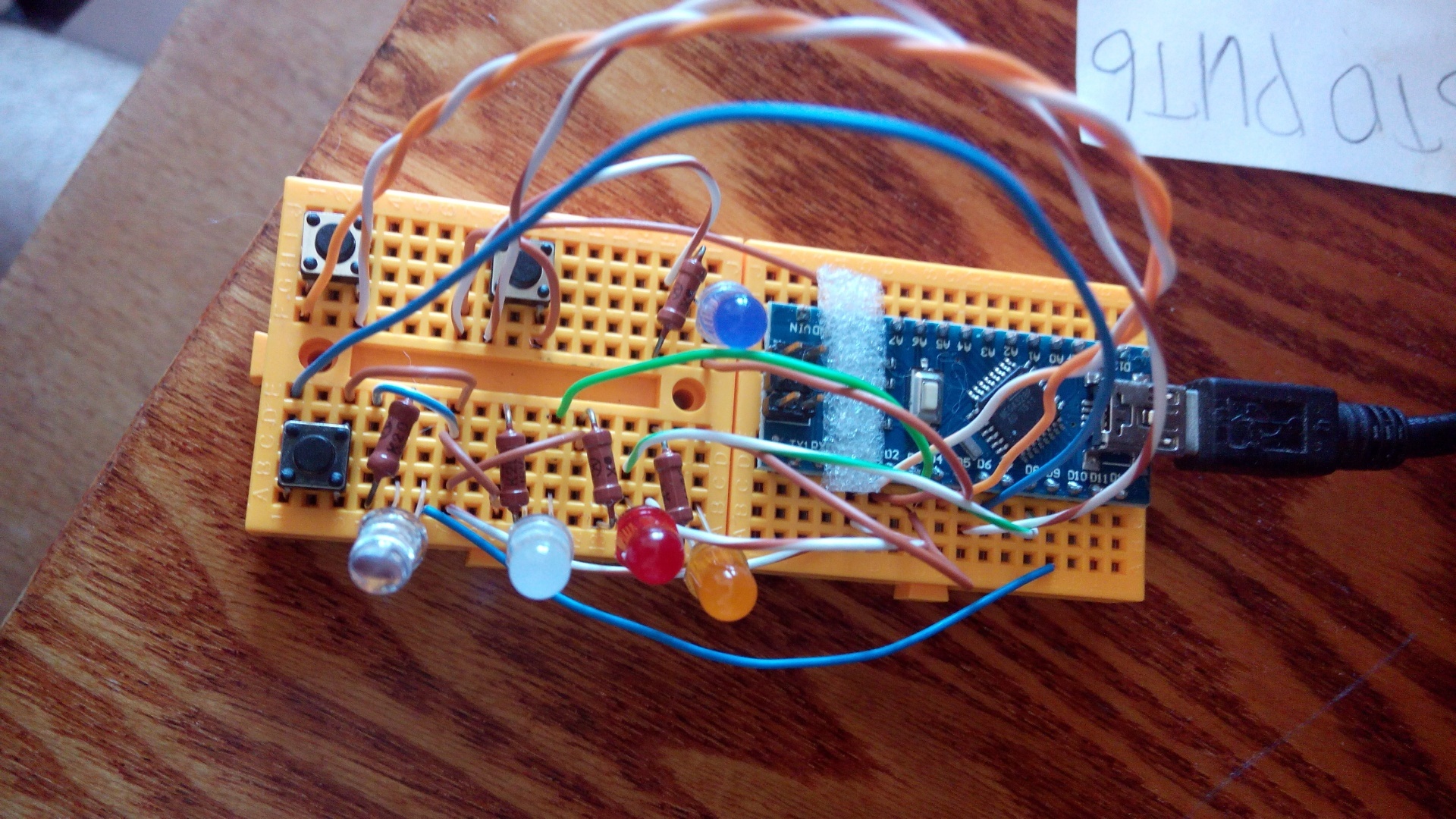
One button is the start-stop button itself, the second is the clutch pedal, and the third is the button, holding it said “the engine is running”. Diodes signaled the operating mode: ACC, On, ReadyToStart, Starter and “engine running”. Subsequently, instead of some diodes, relays were connected that snapped and simulated the position of the key in the corresponding position.
I’ll probably disappoint some here: there is no magic. All magic consists in that by reels to close contacts of the ignition lock in the same way as the key would do.
The first interesting difficulty appeared and challenged my logical thinking. Thinking won.
Typical contact operation diagram in the ignition switch
Off: everything is open
Acc: B1-Acc
On: B1-Acc-Ig1 and B2-Ig2
Starter: B1-Ig1 and B2-St
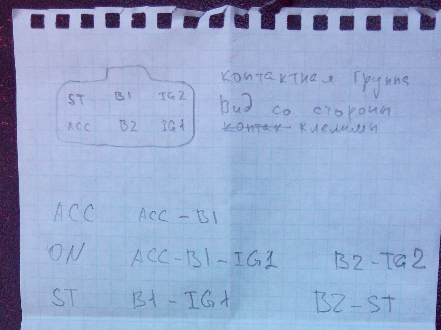
I decided to repeat the operation scheme exactly, although this is not certainly can be simplified.
Short explanations:
B1, B2 - power supply + 12V
Acc - power accessories (radio, cigarette lighter)
Ig1 - ignition (ECU,
gas pump, headlights) Ig2 - interior fan and something else
St - power to the starter
Here I want to say about the flowing currents: not measured, but evaluated. Since (almost) all large consumers in the car are fed through a relay, the total current through the contacts of the ignition switch should not exceed a couple of amperes. This is the current that is needed to power all of these relays. A test ride with 10A rails confirms this, neither the relay nor the wires are hot.
Let us return to solving an interesting problem: how to use a relay to simulate the work of a contact group of an ignition switch. With the second approach, a solution was found. Do you want to know him?Send SMS to a short number. Here it is, beautifully and elegantly fit in four tracks:
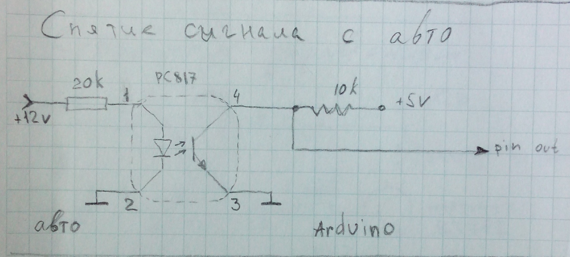
The next interesting task is how to understand that the engine is working. There are several ways. The simplest ones are by the tachometer signal and by the lamp on the dashboard. The most logical one is, of course, by the tachometer because the lamp goes out belatedly. We will try it. We’ll leave the lamp just in case, if suddenly it doesn’t work on the tachometer. I will say in advance - it turned out on the tachometer. I open RTFM on the car, looking for a wire on the dashboard, which is responsible for the tachometer. Although I don’t have a tachometer on the panel, I have such a wire, for my happiness. Parallel to this wire. And suddenly I realize that the car has a dirty voltage of 10..14V, and Arduino loves clean and 5V. "Surely! I need a galvanic isolation ”- I think and I am surprised at how I know such words. I called my friend, from whom I took an arduino, he says: “Optocoupler. Busy. Bye ”and hangs up. Google in Yandex and indeed, the situation is saved by the very popular Sharp PC817 optocoupler. And his price is pleasant - 100 rubles per bunch. Food, buy and make such a scheme
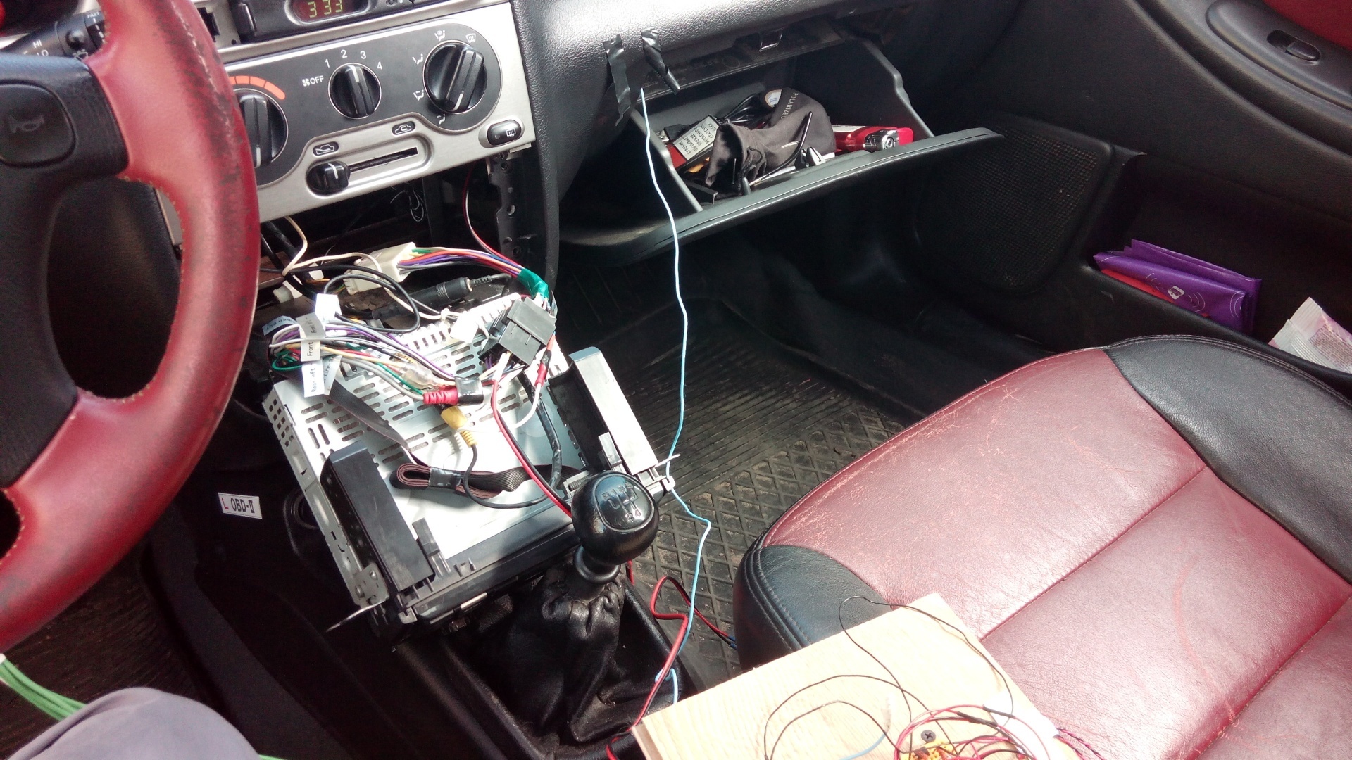
Well, now everything is ready for the assembly of the first test sample. Where are the test samples collected? Well, of course, on plywood! I collect the prototype in the photo below and run into the car, test.

A small stage of connection. Power arduiny from a laptop, power relays from a car through a stabilizer. The laptop simultaneously displays the tachometer readings read by the arduino.


An exciting moment. I press the button. The relay clicks, the magnetologist turns on. I press the second time - Again the clicks of the relay and the gas pump buzzed, the interior fan started, the panel lit up, waiting for start. I hold the clutch pedal simulator, mentally cross my fingers and press the button.
Meanwhile, it was, as I recall, a warm and sunny day in the last month of summer. Rare clouds floated across the sky. The foliage on the trees was green, but already knew that it would soon fall. Two students in short skirts walked past, apparently returning from school.
Duck, I press the button and time slows down from excitement. I clearly hear the relay click, the interior fan shuts off, it seemed to me that I even see how the electrons ran through the wires to the starter, clicks on the retractor relay, the bendix breaks off its place and insists on the flywheel, the starter starts to turn the engine. Half a second! The engine is running, the starter is resting, the interior fan has started working again, the radio has played.
Meticulous skeptics will say that if the system worked the first time, then you did something wrong. And they will be right. In the following attempts, the car did not start with a single press. The solution was simple: when trying to start from the tacho, a spurious signal about high revs and an arduin flew in, thinking that the engine was already running, did not spin the starter. It was not for nothing that a laptop was standing nearby, which displayed the speed ;-) I corrected the sketch so as not to check the speed for the first 100ms and the problem was solved.
Once the system works, you can assemble it from plywood into a small box and, as some say, in production. I was afraid to leave a convenient relay unit and decided to put real automobile five-pin relays. So you need to assemble your relay control unit. Of course, in the same board and solder arduino.
Having searched how it is now fashionable to make printed circuit boards, I learned about LUT technology. For those who are not in the know, LUT is a laser-ironing technology. Yes, with the help of a laser and an iron they make boards :) All day until 5 in the morning I went to draw the boards in the PCB editor. Then the transfer, which, to my surprise, was obtained only the second time. Then etching. To "chat" and get out the board, I tied an aluminum wire to it. Knowledgeable people already laughed, because the wire dissolved faster than copper foil. In general, this stage was completed quickly and showed me this

Akhrenev, from his own coolness, began to think how to drill holes for me. Drilling is too hard and not convenient, there is no boring machine and no one to take from. Well, it doesn’t matter, because the rumor on inventions is cunning. Tricky goal told me to make a boron machine from the engine of a radio-controlled machine. Here's more fun, I thought. “Do it,” said a sly goal. As a result, such a miracle was made.

To understand the size: the length of the motor is about two centimeters. In the manufacturing process were used: super-glue, heat shrink and the rod from the handle.
Video work drills. The soundtrack is chic
A couple of evenings went to the wiring details. It turned out pretty cool, as I myself think, almost like in adults.

When connected, the board did not work. She randomly scooped up relics and, in general, behaved ugly. Not the way a good girl should behave. It took a couple of days to find the problem. The answer turned out to be that I used soldering acid as a flux when soldering, and this acid is conductive, and unscrupulously spent current holidays on my circuit board. After thoroughly laundering the board with alcohol, the current carousel carousel stopped and the board earned exactly as expected. During tests, it turned out that the MPSA44 transistors in the TO-92 package are very hot and were replaced by real domestic KT972A in the 192 case. They are barely warm in work.
The fee is made, it's time to make her ahouse building. The case was cut from scraps of foamed PVC. Great material for needlework, brush. Glued and dried.
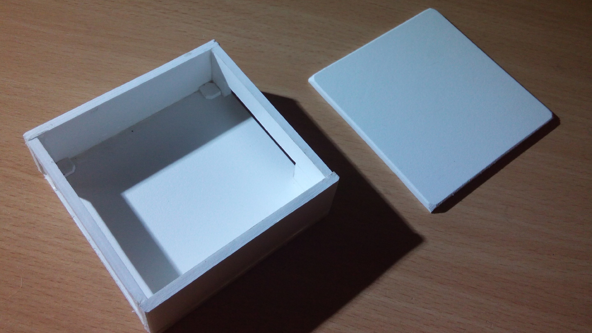
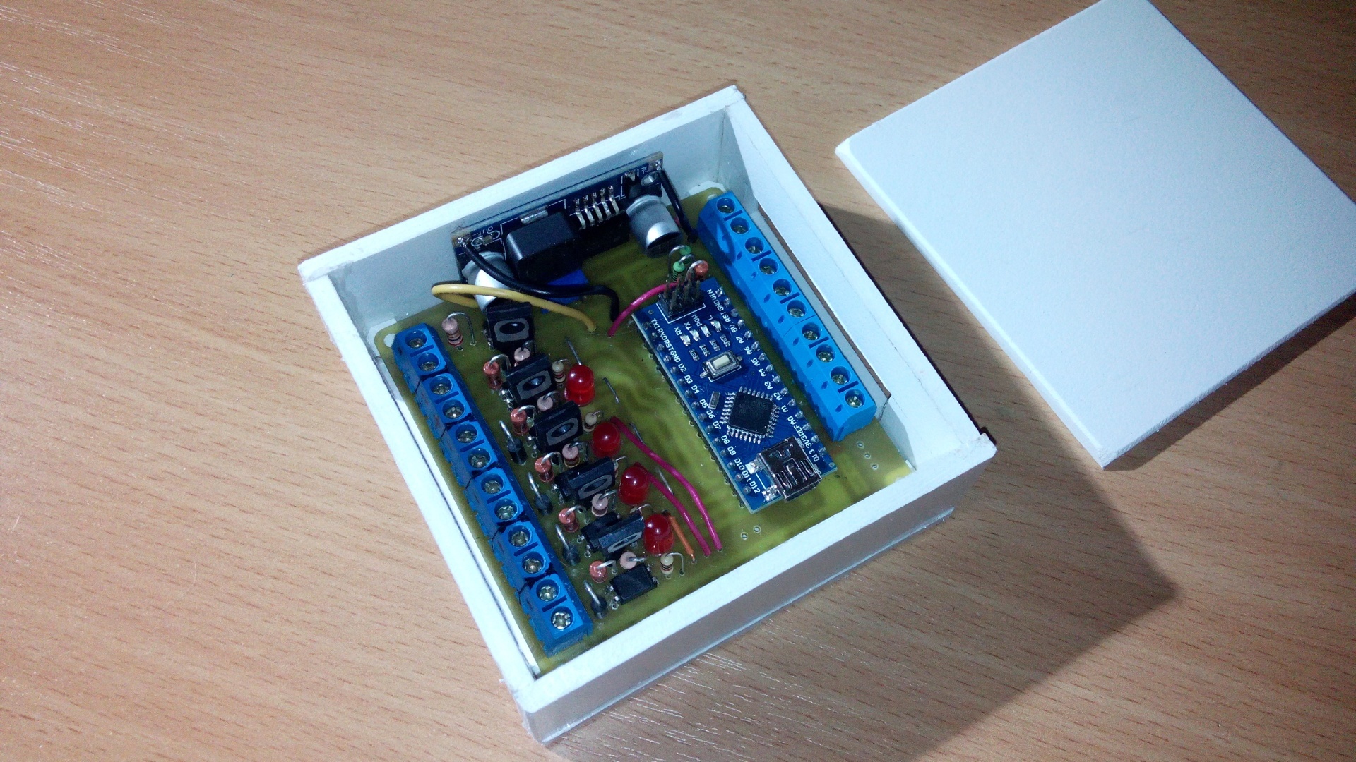
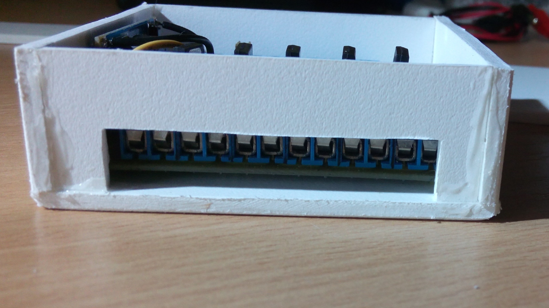
For ease of installation, subsequently, the blue terminals were replaced with white ones, and before the final assembly, one side of the board was covered with a zaponlak. Red car - red varnish!
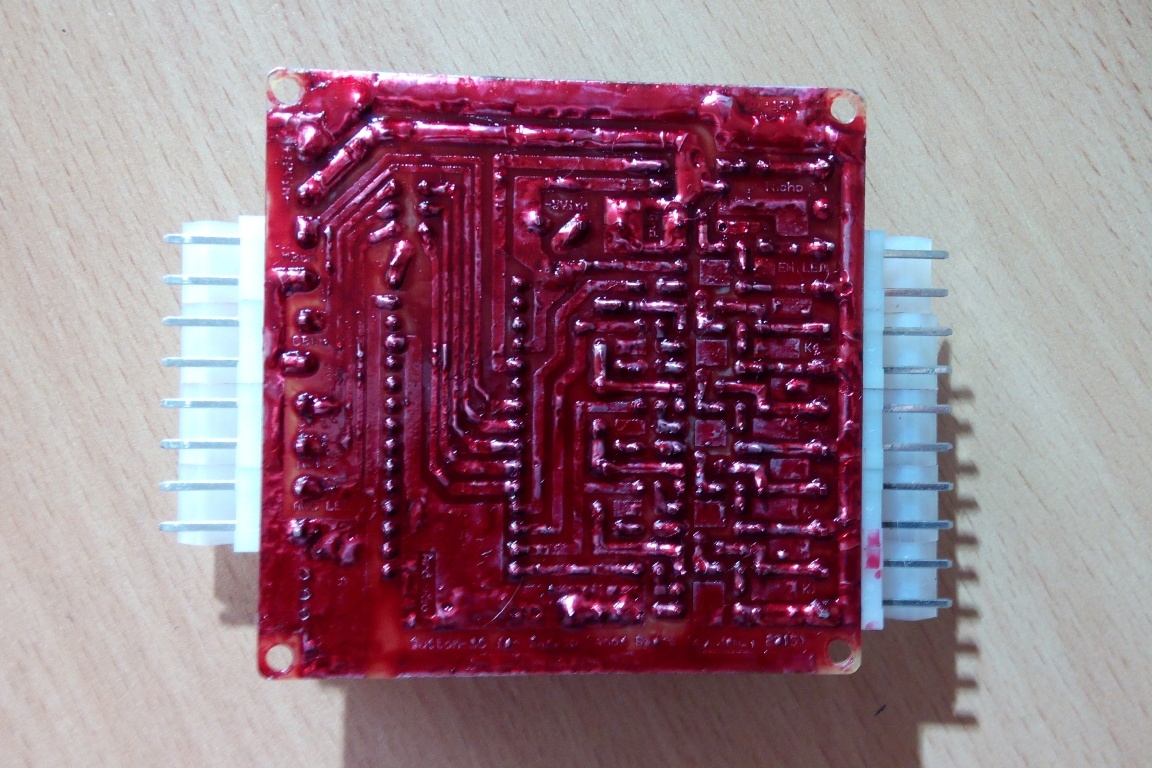
It is in this form that this product was subsequently installed in the machine.
Before these, I imagined myself a cool macrograph and took some high-quality photos on a Chinese phone
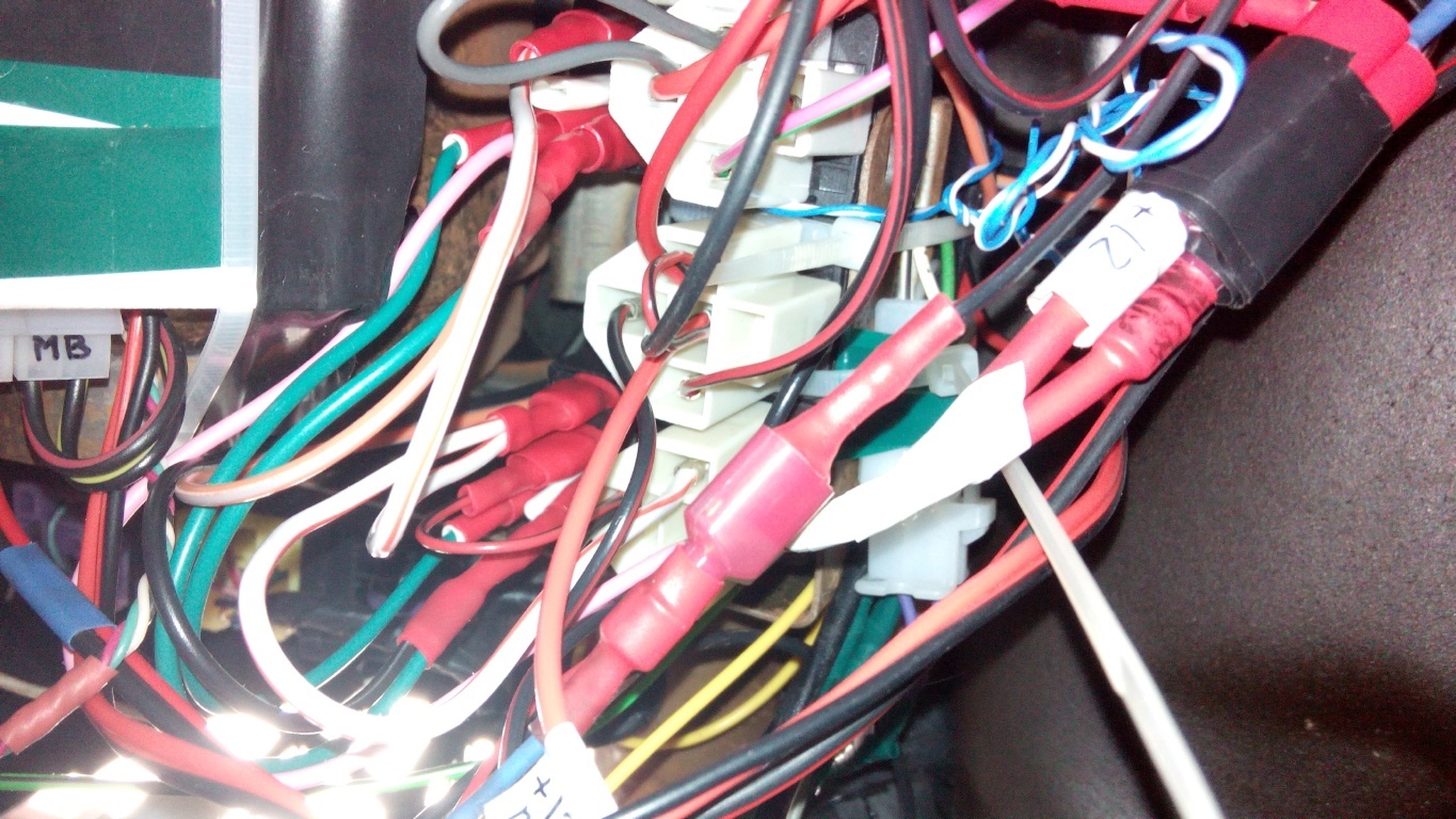
It took several hours to install the system in a car. The invisible part is a hell of a mess of wires.
Well, the visible part fit itself elegantly into the interior.


As it should be at the end of such articles - video work
Afterword.
After four months of operation, I can say that I am very pleased with my craft.
Frost at -30C withstands and works.
I don’t see the point of attaching a sketch for arduino, because the code is very simple.
Now that I got your attention, let's continue. The first time the idea that I want to exclude the key from using the car, visited me when I zae ... I was tired of opening the trunk, which opened exclusively with the key. I had to get the key from the ignition switch to open the trunk. How I made a trunk opener is an article for drive2.ru rather than geektimes, so I will skip the trunk and move on to the description of creating a car start button.
As expected, the study of the question began on aliexpress. This paradise of various junk provided a huge selection of the same solutions. There were three different things, the rest differed only in shops and price. Solutions from neighbors on the continent were a ready-made kit with instructions (head module, wires and button). More or less good, but I did not like the algorithm of their work.
Thinking what this ready-made kit was all about, I realized that it was a microcontroller, a button with LEDs and reels that close the ignition switch contacts. As you already understood, it was in this place that the thought of arduino appeared.
At the time this thought appeared in my head about arduino, I only knew that it was a microcontroller. And that’s it. I did not even know what a microcontroller is. I called a friend who could know. He said that he knew that he knew that the idea was good, and in general come, I will give you a set for experiments. Having taken from comrade arduino nano 3, a 4 relay unit, a circuit board and enthusiasm went home, dreaming on the road how this button would look in action.
Further, in order to understand what I might encounter, I looked for whether anyone had already done a similar thing. Found an article on drive2. There, the man did not just do, but made the second version for the second car. We signed up, talked, and found out that there were a lot of strangers to me, but there was nothing super complex. And the work began to boil.
A couple of days I learned to blink diodes and got some strange pleasure from this. Having played enough, I realized that it is time to learn to turn on / off the diode by pressing a button. Knowing people have already understood, but I will say to unknowing people that I learned about the effect called “contact bounce”. Having dealt with it, he set about creating the first prototype.
One button is the start-stop button itself, the second is the clutch pedal, and the third is the button, holding it said “the engine is running”. Diodes signaled the operating mode: ACC, On, ReadyToStart, Starter and “engine running”. Subsequently, instead of some diodes, relays were connected that snapped and simulated the position of the key in the corresponding position.
I’ll probably disappoint some here: there is no magic. All magic consists in that by reels to close contacts of the ignition lock in the same way as the key would do.
The first interesting difficulty appeared and challenged my logical thinking. Thinking won.
Typical contact operation diagram in the ignition switch
Off: everything is open
Acc: B1-Acc
On: B1-Acc-Ig1 and B2-Ig2
Starter: B1-Ig1 and B2-St
I decided to repeat the operation scheme exactly, although this is not certainly can be simplified.
Short explanations:
B1, B2 - power supply + 12V
Acc - power accessories (radio, cigarette lighter)
Ig1 - ignition (ECU,
gas pump, headlights) Ig2 - interior fan and something else
St - power to the starter
Here I want to say about the flowing currents: not measured, but evaluated. Since (almost) all large consumers in the car are fed through a relay, the total current through the contacts of the ignition switch should not exceed a couple of amperes. This is the current that is needed to power all of these relays. A test ride with 10A rails confirms this, neither the relay nor the wires are hot.
Let us return to solving an interesting problem: how to use a relay to simulate the work of a contact group of an ignition switch. With the second approach, a solution was found. Do you want to know him?
answer
The next interesting task is how to understand that the engine is working. There are several ways. The simplest ones are by the tachometer signal and by the lamp on the dashboard. The most logical one is, of course, by the tachometer because the lamp goes out belatedly. We will try it. We’ll leave the lamp just in case, if suddenly it doesn’t work on the tachometer. I will say in advance - it turned out on the tachometer. I open RTFM on the car, looking for a wire on the dashboard, which is responsible for the tachometer. Although I don’t have a tachometer on the panel, I have such a wire, for my happiness. Parallel to this wire. And suddenly I realize that the car has a dirty voltage of 10..14V, and Arduino loves clean and 5V. "Surely! I need a galvanic isolation ”- I think and I am surprised at how I know such words. I called my friend, from whom I took an arduino, he says: “Optocoupler. Busy. Bye ”and hangs up. Google in Yandex and indeed, the situation is saved by the very popular Sharp PC817 optocoupler. And his price is pleasant - 100 rubles per bunch. Food, buy and make such a scheme
Well, now everything is ready for the assembly of the first test sample. Where are the test samples collected? Well, of course, on plywood! I collect the prototype in the photo below and run into the car, test.
A small stage of connection. Power arduiny from a laptop, power relays from a car through a stabilizer. The laptop simultaneously displays the tachometer readings read by the arduino.
An exciting moment. I press the button. The relay clicks, the magnetologist turns on. I press the second time - Again the clicks of the relay and the gas pump buzzed, the interior fan started, the panel lit up, waiting for start. I hold the clutch pedal simulator, mentally cross my fingers and press the button.
Meanwhile, it was, as I recall, a warm and sunny day in the last month of summer. Rare clouds floated across the sky. The foliage on the trees was green, but already knew that it would soon fall. Two students in short skirts walked past, apparently returning from school.
Duck, I press the button and time slows down from excitement. I clearly hear the relay click, the interior fan shuts off, it seemed to me that I even see how the electrons ran through the wires to the starter, clicks on the retractor relay, the bendix breaks off its place and insists on the flywheel, the starter starts to turn the engine. Half a second! The engine is running, the starter is resting, the interior fan has started working again, the radio has played.
Meticulous skeptics will say that if the system worked the first time, then you did something wrong. And they will be right. In the following attempts, the car did not start with a single press. The solution was simple: when trying to start from the tacho, a spurious signal about high revs and an arduin flew in, thinking that the engine was already running, did not spin the starter. It was not for nothing that a laptop was standing nearby, which displayed the speed ;-) I corrected the sketch so as not to check the speed for the first 100ms and the problem was solved.
Once the system works, you can assemble it from plywood into a small box and, as some say, in production. I was afraid to leave a convenient relay unit and decided to put real automobile five-pin relays. So you need to assemble your relay control unit. Of course, in the same board and solder arduino.
Having searched how it is now fashionable to make printed circuit boards, I learned about LUT technology. For those who are not in the know, LUT is a laser-ironing technology. Yes, with the help of a laser and an iron they make boards :) All day until 5 in the morning I went to draw the boards in the PCB editor. Then the transfer, which, to my surprise, was obtained only the second time. Then etching. To "chat" and get out the board, I tied an aluminum wire to it. Knowledgeable people already laughed, because the wire dissolved faster than copper foil. In general, this stage was completed quickly and showed me this
Akhrenev, from his own coolness, began to think how to drill holes for me. Drilling is too hard and not convenient, there is no boring machine and no one to take from. Well, it doesn’t matter, because the rumor on inventions is cunning. Tricky goal told me to make a boron machine from the engine of a radio-controlled machine. Here's more fun, I thought. “Do it,” said a sly goal. As a result, such a miracle was made.
To understand the size: the length of the motor is about two centimeters. In the manufacturing process were used: super-glue, heat shrink and the rod from the handle.
Video work drills. The soundtrack is chic
A couple of evenings went to the wiring details. It turned out pretty cool, as I myself think, almost like in adults.
When connected, the board did not work. She randomly scooped up relics and, in general, behaved ugly. Not the way a good girl should behave. It took a couple of days to find the problem. The answer turned out to be that I used soldering acid as a flux when soldering, and this acid is conductive, and unscrupulously spent current holidays on my circuit board. After thoroughly laundering the board with alcohol, the current carousel carousel stopped and the board earned exactly as expected. During tests, it turned out that the MPSA44 transistors in the TO-92 package are very hot and were replaced by real domestic KT972A in the 192 case. They are barely warm in work.
The fee is made, it's time to make her a
For ease of installation, subsequently, the blue terminals were replaced with white ones, and before the final assembly, one side of the board was covered with a zaponlak. Red car - red varnish!
It is in this form that this product was subsequently installed in the machine.
Before these, I imagined myself a cool macrograph and took some high-quality photos on a Chinese phone
high quality photos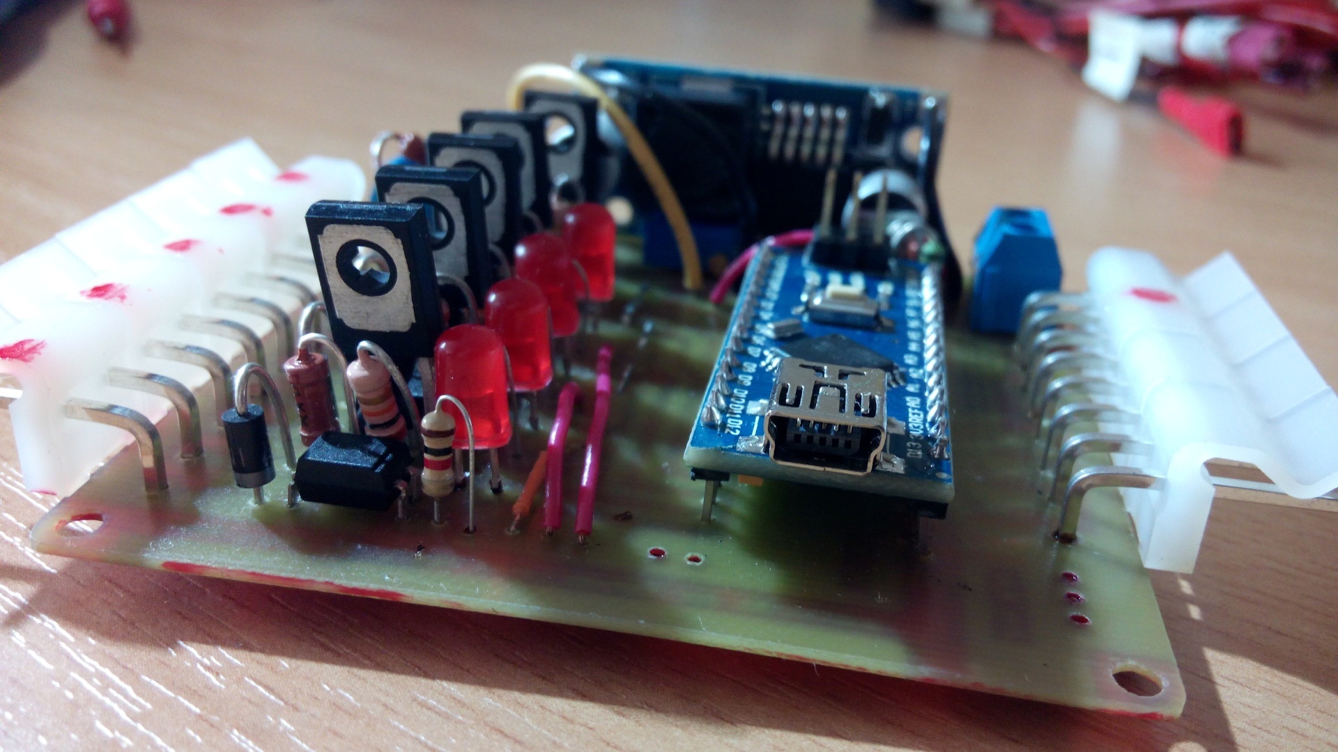


It took several hours to install the system in a car. The invisible part is a hell of a mess of wires.
Well, the visible part fit itself elegantly into the interior.
As it should be at the end of such articles - video work
Afterword.
After four months of operation, I can say that I am very pleased with my craft.
Frost at -30C withstands and works.
I don’t see the point of attaching a sketch for arduino, because the code is very simple.