Computer twisting - it’s very simple

Having played enough with building computers from my childhood in a variety of ways, using both then and modern technologies, I decided that it was time to switch to something more substantial. The first step, so that later there was less temptation to build something else, heroically set about clearing the workplace with the goal of giving the accumulated good to some young technicians. However, as often happens, even the process of analyzing the rubble turned out to be quite fascinating - there were many interesting things that I already forgot about (or did not remember at all). In particular, it turned out that I had a lot more tools and consumables for wire wrapping than I thought.
Although in my time I spent as much as five minutes trying out this technology, something didn’t work out for me (the curvature of the hands turned out to be more than acceptable), and everything was moved to a distant drawer. I really do not like to give up on any business - I always try to bring everything, if not to its completion, then to the realization that I can definitely do it if I really want to. Therefore, I decided to make the young technicians happy later, and before that, still collect some gizmo using a wrap-up installation.
I did not think for a long time about the assembly gizmo - there was one more ancient computer, which my hands never reached before in childhood or now. It was a “Specialist”, developed in 1985 and published in the journal “Modelist-Constructor” in 1987. Since there is a ton of information about this computer (however, as about other similar ones), I will not go into its features, I will just focus on wrapping technology and their impressions of it.
Note - the article talks about almost dead technology, there are no useful or interesting know how and the like, the great revelations are completely missing, so it’s worth reading only if you don’t have a more useful / interesting activity at the moment, or if you are an ardent computer enthusiast necrophilia.
So, the Specialist-M modification was taken as the basis, which differs from the original computer, mainly by using 565RU5 memory chips (8 pieces of 64 Kbit) instead of 565RU3 (24 pieces of 16 Kbit), and published in MK 1991 year. He practically didn’t make his own changes - he used a ready-made quartz oscillator lying on hand instead of a separate quartz and a generator on LN1, and he took a modern EEPROM instead of RF2. He even placed the details on the circuit board as they were placed on the original printed circuit board from the magazine.
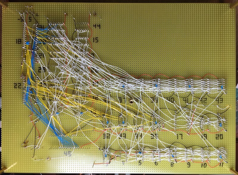
Well, let's move on to the installation itself and the tools / consumables for it. The general meaning is that on special contact pins of a quadrangular cross section (with fairly sharp angles) using at least a special tool a single-core wire is wound, made in the region of 6-8 turns (or something like that). When wrapping, the corners of the contact pins cut into the wire, and almost cold welding is obtained. It is said that such a connection is more reliable than soldering, and it is also easier to repair it.
Note - I could not find a clear explanation of the practical nuances of this technology, so I constantly invented bicycles. I think in some cases (if not most) they were bicycles with triangular wheels and a wheel under the ass, so I do not need to take my research as an example of the right approach to the process!
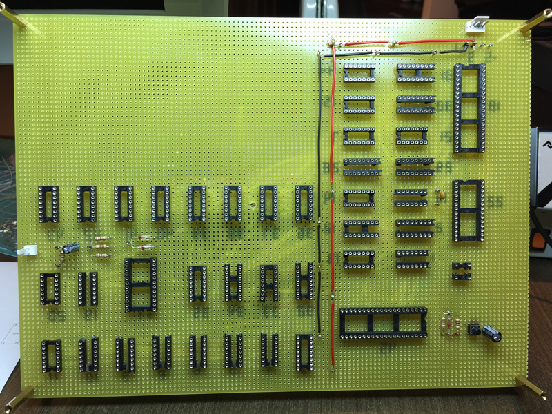
So, the first problem arises with the fact that you can connect only these very special pins. In the case of microcircuits, everything is relatively simple - special (again special!) Panels are taken for wrap-up, in which the legs are already made in the right form:
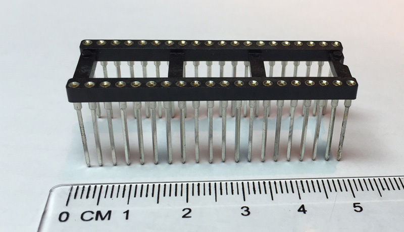
And here the first nuance is immediately apparent - the cost. These panels are quite expensive - a few dollars a piece. Given the cost of the used ancient microcircuits, I can say that each panel in the project cost significantly more than the microcircuit that stood in it. And for the total cost of the panels, it was possible to order production of a couple of copies of the printed circuit board at a cheap place (naturally, if it is already developed and the files are ready for production).
With parts such as resistors / capacitors in general, an ambush. To be honest, I still don’t understand what to do with them. In some cases, the resistors could be screwed onto the pins, although the diameter of the leads was on the verge of what the tool could swallow. With other details, such a trick did not pass at all - the conclusions are too thick.
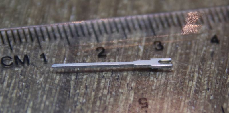
In general, there are separate pins of two types for this - either in which you can insert the pins (in fact, just separate pins from the panels for microcircuits), or pins to which the parts need to be soldered. Although this reduces the purity of the experiment, I chose pins that can be soldered, for two reasons - firstly, you can make reliable contact regardless of the diameter / type of output, and secondly, I still only had this type of pins.
Unfortunately, at one time I forgot to order also a tool for mounting pins on a board, which I regretted in the process. It is possible, in principle, to use pliers, but this becomes problematic if the pin needs to be inserted in a place on the board where there is already a lot of mounting around. In this case, creating a support for the board in this place is extremely difficult, and you have to push with all your strength. At some point, I practically pierced my palm through, and then I tried to reduce the number of pins to an absolute minimum. But a special tool, in theory, drives the pin into the board with a blow (there are electrical devices, and there are mechanical ones with a spring), so it seems like the board can be kept on weight. But I don’t know for sure - I haven’t tried it.
By the way, I also missed the board itself. I had it without metallization at all, just holes. Now I understand that the presence of power buses on the board would save me a lot of time and effort, but then it seemed logical that everything should be done over the wire.
Another thing that was missing for me was labels for marking microcircuit pins.

In general, I wanted to order them, but at that moment they were not available from the supplier. I think the use of these things could save 10-20 percent of the installation time, and there might not be those few mistakes that I made in the process. I was even going to print labels on paper, but I didn’t figure out how to accurately punch holes, and trying to pierce the paper directly with the findings looked just awful.
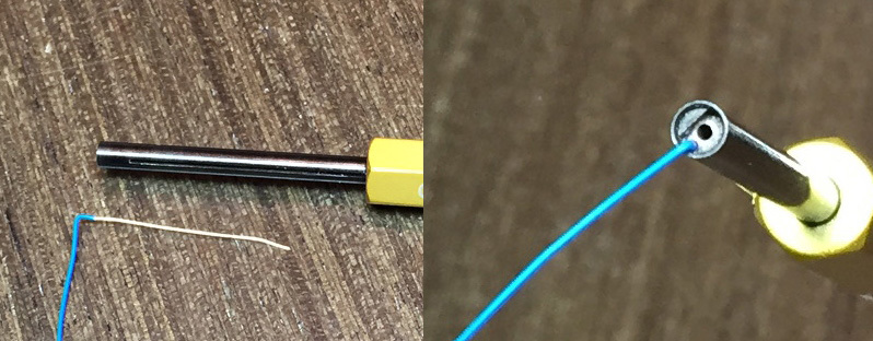
The main working part of the winding tools is a pin in which there are two longitudinal holes. One larger diameter is in the center of the pin, a contact pin is inserted into it, onto which it is planned to wind the mounting wire. The second hole is thinner and, naturally, is shifted to the very edge, the stripped end of the mounting wire is inserted into it. When the tool rotates around the longitudinal axis (and, in fact, around the contact pin), the wire is wound around this pin itself.
There are two options for winding - standard and modified. In the standard version, only the stripped part of the wire is wound around the pin (well, maybe a quarter of a turn with insulation). With the modified version, the first couple of turns are obtained with insulation, then a stripped wire is already coming. The modified method will be more reliable (since the wire that is potentially bent during further installation and operation is protected by insulation, and is not located exactly at the place where the insulation ends), but takes up more space on the pin.
I have two almost identical completely manual tools, one for standard wrapping, and the second for modified:
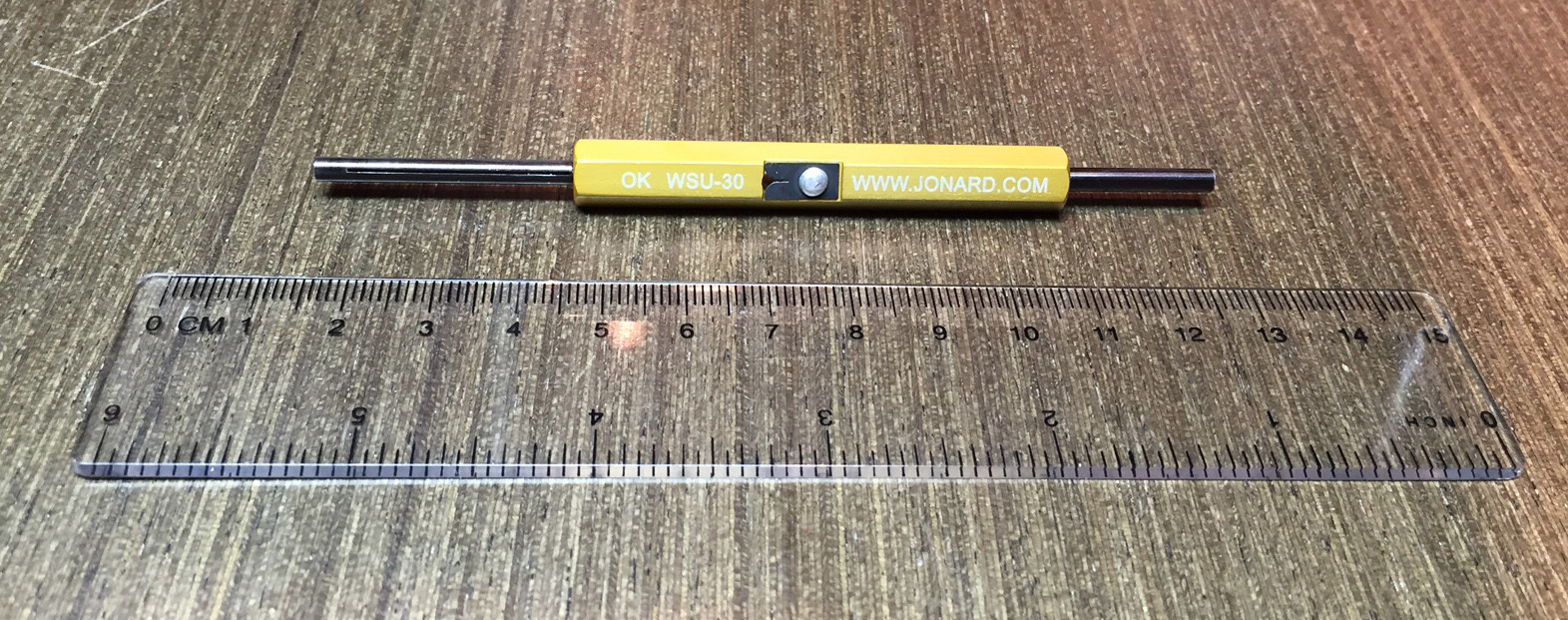
You just need to rotate these tools with your fingers. The third tool (for the modified wrapping) was semi-automatic - the wrapping occurred when the handle was pressed, in almost one motion. At first I decided to use this particular tool, but the percentage of marriage was unacceptable. I simply could not control the position and pressure of the working part, especially if this was not the first cheat on the pin. I think there is some subtlety in using such a tool, but I still did not understand it, so I decided to do everything with a hand tool.

By the way, hand tools, despite their simplicity, are quite versatile. In addition to wrapping, they can also strip the wire (the stripper is in the middle), and also, if necessary, unwind the wrapping made. To do this, the tool is put on the contact pin with a short end and rotates in the direction opposite to the direction of the wrap.
For some reason, I chose the standard wrapping, although now, without hesitation, I would use a modified one. The problem is that when stripping the wire, it is almost inevitable that the conductor itself is slightly damaged in the place of the insulation cut. And with the standard method, this place is also just the point of application of force for any movement of the wire, i.e. the probability of a wire break here is quite high.
I also found a tool for cleaning / trimming the wire, but I, after a little testing, decided not to use it. Perhaps, in some cases, it would be better than the built-in wrapping tool, but I was too lazy to understand the intricacies, the built-in sweeper worked for me, and it was more convenient to cut with cutters.
Speaking of the wire. It is called so - wire for wrap-around installation, single-core, rather soft, sold in different colors. Each tool is designed for a wire of a strictly defined diameter, I had everything AWG 30 - about 0.26 mm in diameter. By the way, the wire, although for wraparound mounting, is soldered awesomely. It is a pity, I did not know this before, I could use it on my previous projects instead of MGTF. True, isolation, unlike MGTF, melts very easily.

Before going to bed, it was necessary to decide how to lay the wires - in bundles, or at the shortest distance. Harnesses, of course, look neater, and it was them that I used in previous projects. However, in numerous wraparound photos, I saw that very often the “shortest distance method” is used here - it also looks pretty good. In addition, with such an installation, there seems to be less mutual interference - but it didn’t really worry me, in such projects it is almost never a problem. As a result, for a change, I decided to try the installation "for the shortest time" ...
There was still a small problem with the absence of panels of some sizes. Unfortunately, I had to break the existing panels with wire cutters to get what I needed, so the appearance of the structure was slightly affected by this.
Directly mounting, as usual, began with power circuits. I took an eye on the power consumption and decided that the AWG 30 cross-section should be enough, especially if we divide the circuit into several sections and apply power to each section independently. Just when wiring the power circuits and worked out the technology in a first approximation. It immediately turned out that it was extremely difficult to achieve beautiful, perfectly even wires. In principle, after a while I came up with a method, but the time spent on it was high, so I put up with the fact that beauty would not work.
During the work with the power circuits, I got my hand a little bit, and then the work went faster. In general, of course, it turned out faster than soldering. It’s hard to express in numbers, but I think that 20-40% of the time can be saved. Moreover, the process is much more environmentally friendly - no fumes and all the accompanying effects.
However, I absolutely do not understand why one of the advantages of wrapping is the ease of repair (at least, they say so). On the contrary, in one place I was mistaken, and I needed to transfer the wire from one mounting pin to another. The problem was that the “wrong” wire was at the very bottom of the pin, and two more wires had already been wound over it, which also had to be dismantled. In the version with soldering, they would be soldered back, and that’s all, but here they had to be changed - you can’t wind the “untwisted” end back. But those wires from the other end were also below the pins! A chain reaction began, which ended with the remounting of almost a dozen wires. There may be a wonderful way to avoid such situations, but I don’t know him ...
The more I mounted the wires between the pins of the microcircuits, the easier it was to move, and the more I did not like the need, in the end, to begin installing components that were not intended for wrap-up - blocking capacitors, a certain number of resistors / capacitors / diodes and connectors.
At first I thought to solder the blocking capacitors to special pins (which I mentioned earlier), and already connect these pins with wire to the pins of the microcircuit panels. However, this is electrically incorrect (blocking capacitors should be as close as possible to the power supply terminals of the microcircuits), and the load of the corresponding pins on the sockets (most of them no longer have space for additional wrapping) finally made the choice in favor of soldering capacitors directly to the pins of the sockets of the microcircuits. It turned out that the pins, like the wire, are soldered perfectly, so the installation of capacitors did not take much time. Some of the findings of the resistors were screwed up; for the rest, single pins were installed (as I said, with the risk of serious hand injuries). If there was a tool for pins, it would carry much less.
In addition to loose parts, a thicker wire was laid power bus, from which power is distributed in separate pieces of the circuit.
By the way, it took about 40 m of wire to complete the installation.
After that, finally, there came an exciting moment of the first inclusion.
To begin with, without microcircuits in the panels I was convinced that in the right places there is earth and the corresponding power, after which I inserted all the “small” microcircuits and tried with them already. To some surprise, the video signal with the correct synchronization appeared immediately. However, an attempt to get some kind of picture revealed that I forgot to mount 8 wires to the shift register. After the installation, the missing video part seemed to work (as far as it could be verified without a working processor / memory). True, it became clear that the 1554 series multiplexers (something like the 555 series at the time of purchase of all spare parts in the store were not) didn’t want to work with the usual TTL logic, so I had to urgently look for the 555 series microcircuits. After installing them in the video node everything finally fell into place.
The next problem was an incorrect processor clock signal. It seems that the temporary circuits of the newer series of microcircuits (compared to those used in the original circuit) did not fit the method by which the author generated this signal (to be honest, and not surprising - everyone can carefully look at the way F2 is formed). However, replacing the microcircuit with a more fossil problem solved it, but I did not need more. However, these showdowns helped to reveal one more point - in the magazine scheme, F1 and F2 were mixed up! I had to swap two wires, while again faced with the fact that the dismantling of one wire can pull a chain reaction.
Finally, it's time to insert the processor, memory, and I / O port into the sockets.
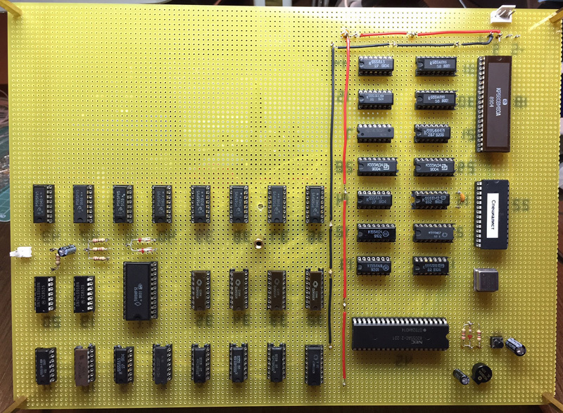
I didn’t have any particular illusions about the device’s operability in full, so instead of a control monitor, I immediately installed a ROM with a test program. This program does not use RAM for its internal purposes, so the chances of at least some kind of processor work are increased - there are much fewer nodes between the processor and ROM than on the way from the processor to RAM. However, as I often did with previous projects, the device started working suddenly and immediately:
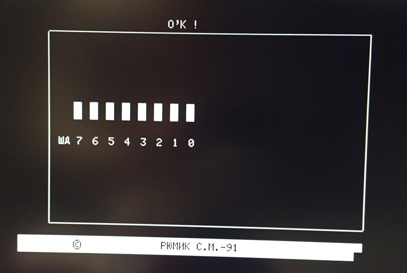
Moreover, the test even showed the full performance of even RAM, which cannot but surprise. 565RU5 microcircuits were never particularly reliable, and even when using new microcircuits, it was commonplace to discard a significant percentage of cases, and here products of 25 years ago, which, moreover, were not handled very carefully, worked without any questions.
After that, I installed a full-time ROM with a monitor and got a picture that I had previously seen only in the magazine:

I didn’t find any special surprises for myself during the process, regarding the wrapping technology I remained of the opinion that earlier it could really be convenient both for prototyping and for making single copies of devices. Now, first of all, the modern elemental base (for surface mounting) simply eradicates the very idea of cheating on the vine. For relatively small crafts / experiments with "large" parts, solderless prototype boards (which, moreover, do not require very expensive panels) will completely come down, and for the rest, a printed circuit board can be made quite easily, quickly and for reasonable money - even at home with LUT, at least an order in production.
A small addition from 11/11/2015:
I decided to play with a small project with a clock frequency of 33 MHz. I assembled it on a solderless breadboard and quite expectedly found that it did not work - too large stray capacitances. I thought about what to do next - to solder or collect on a wire, and suddenly I realized that it felt like wrapping would be easier. Indeed, in an hour everything was assembled and launched without any problems at all ...