New life of old iron
This is the story of connecting the "old" ATX power supply to new mini-ITX motherboards that do not have this connector.
In the beginning there was a word , and then he got into a mess.
With longing, watching the growth of the exchange rate and the decrease in the assortment on the shelves, I made a strong-willed decision to replace the home laptop with a new PC desktop (and expropriate the free laptop for personal needs). After rummaging around "by the guts" in a personal household: monitor (was connected to the laptop as an external one), 2.5 ”500 GB HDD, 8 GB SO-DIMM DDR3 memory module. It remained for small - the motherboard, processor and case with power supply (keyboard and mouse were also available).
I personally like compact solutions (possibly due to limited work space) and the soul lies with mini-ITX standard motherboards. Graphics processing, video and "heavy" games are not fond of. therefore, I do not feel the need for a powerful discrete graphics card. In fairness, it should be noted that finding a regular video card in a "low" form factor is also a problem, but I am quite happy with the capabilities of the integrated video card. Earlier, three years ago, I assembled a NAS for home use based on a mini-ITX board with an Intel-Atom CPU installed. There were no special problems during assembly at that time, the device is working properly and is waiting for the expansion of the disk array (the selected case allows you to install 6 (six) HDDs 3.5 ”, there is an additional SATA controller board). Therefore, not expecting tricks, I proceeded to the selection of components.
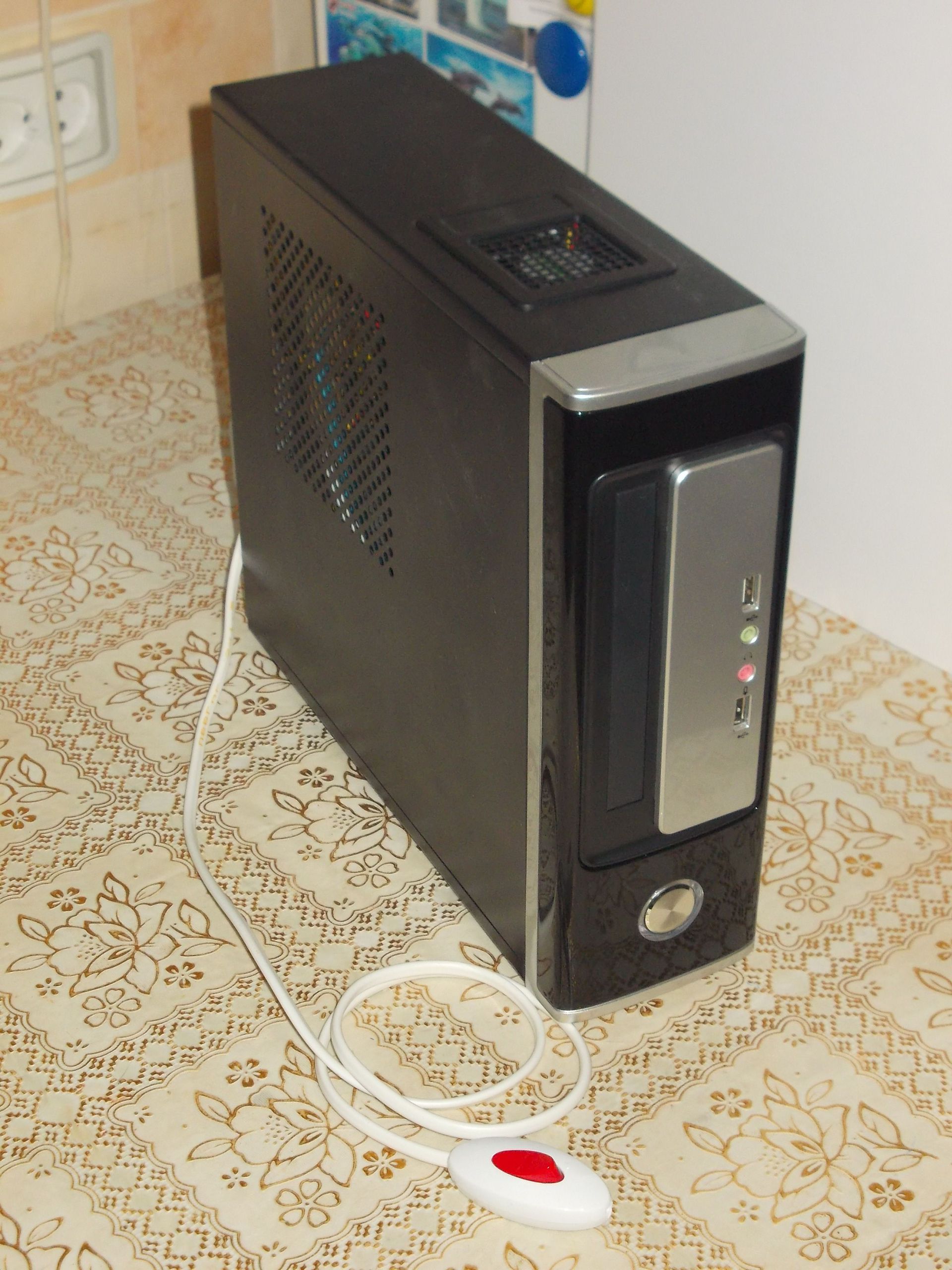
The main limitation in the selection, in addition to the selected mini-ITX form factor, was the presence of a memory module of the SO-DIMM standard (for reference, this is the memory standard for laptops). A small caveat - in addition to laptops, this standard of memory modules is found only on mini-ITX boards and less. The soldered processor did not suit me much (with the expectation of further updating), so the LGA 1155 socket was chosen. As a result of selecting the price / availability / nearest store, we bought a Gigabyte GA-H61TN motherboard and a MiniITX Winsis WI-03 case with an installed 300 PSU Watt ATX standard. Here the ambush awaited!
I follow little changes and innovations in computer components. I heard about the desires to introduce a single +12 V power supply on the motherboards, but not as fast ... The purchased (and already installed in the case) motherboard had a “laptop” DC power connector and a two-pin ATX_19V connector. For a long time, with a dumb question in my eyes, I considered the wiring harness from the power supply and the motherboard: the choice is great, but there is nothing to stick in (there is nowhere). The first desire, to hand over the board and take another with the “correct” power connectors, was violently suppressed by the store staff. After a careful inspection of the board (with a magnifying glass!), Traces of mounting the board into the case were discovered and it was declared impossible to return. (Brief reference: tinned contact pads are located on the circuit board at the mounting holes around the circumference. When mounting the board, the screw head crushes the soft solder and a pronounced trace of “interference” remains. To eliminate installation traces, it is enough to cover the area with a flux and heat it with a hairdryer. The solder will melt and take its “original” form. The main thing is not to overheat (the traces of overheating can no longer be removed) and rinse off the flux residues (although traces of factory flux on the board are found in abundance)) By nature, I am not a scandalous person, “fat and lazy”. There was no desire to swear and delve into the laws, besides a sense of pride leaped up: I am not the manager of the trading floor, I am an engineer. In addition to the “fifth point”, from where many people grow their arms, and which often replaces the head, my head is out of place and my hands are sharpened correctly. The solution to technical problems is my bread! To eliminate installation traces, it is enough to cover the area with a flux and heat it with a hairdryer. The solder will melt and take its “original” form. The main thing is not to overheat (the traces of overheating can no longer be removed) and rinse off the flux residues (although traces of factory flux on the board are found in abundance)) By nature, I am not a scandalous person, “fat and lazy”. There was no desire to swear and delve into the laws, besides a sense of pride leaped up: I am not the manager of the trading floor, I am an engineer. In addition to the “fifth point”, from where many people grow their arms, and which often replaces the head, my head is out of place and my hands are sharpened correctly. The solution to technical problems is my bread! To eliminate installation traces, it is enough to cover the area with a flux and heat it with a hairdryer. The solder will melt and take its “original” form. The main thing is not to overheat (the traces of overheating can no longer be removed) and rinse off the flux residues (although traces of factory flux on the board are found in abundance)) By nature, I am not a scandalous person, “fat and lazy”. There was no desire to swear and delve into the laws, besides a sense of pride leaped up: I am not the manager of the trading floor, I am an engineer. In addition to the “fifth point”, from where many people grow their arms, and which often replaces the head, my head is out of place and my hands are sharpened correctly. The solution to technical problems is my bread! The main thing is not to overheat (the traces of overheating can no longer be removed) and rinse off the flux residues (although traces of factory flux on the board are found in abundance)) By nature, I am not a scandalous person, “fat and lazy”. There was no desire to swear and delve into the laws, besides a sense of pride leaped up: I am not the manager of the trading floor, I am an engineer. In addition to the “fifth point”, from where many people grow their arms, and which often replaces the head, my head is out of place and my hands are sharpened correctly. The solution to technical problems is my bread! The main thing is not to overheat (the traces of overheating can no longer be removed) and rinse off the flux residues (although traces of factory flux on the board are found in abundance)) By nature, I am not a scandalous person, “fat and lazy”. There was no desire to swear and delve into the laws, besides a sense of pride leaped up: I am not the manager of the trading floor, I am an engineer. In addition to the “fifth point”, from where many people grow their arms, and which often replaces the head, my head is out of place and my hands are sharpened correctly. The solution to technical problems is my bread!
The search for a solution to the problem has begun
After reading (!) The user manual for the motherboard, I found out, in addition to the type of connector, that the range of supply voltages is from 9 to 19 volts, and the recommended power supply of the power supply is 190 watts. From personal experience working with laptops from various manufacturers (Samsung, Asus, Acer, Sony, Lenovo), I know, there are different power connectors everywhere! It is frankly lazy to look for the correspondence of the type of connector indicated in the manual with any vendor. The use of a universal power supply for laptops is also not a solution: very often when changing the connector, you must follow the correct polarity of the connection, and there are no polarity information in the manual. And the last, I simply did not see the required power declared by the manufacturer in 190 watts in nature. The option with an external power supply dropped by itself.
Second step
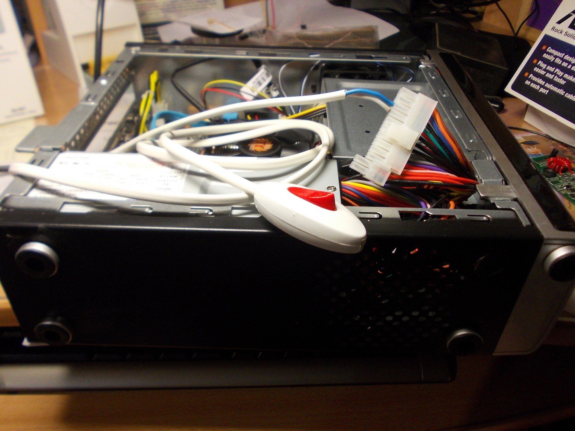
The previously announced power range is also applicable to the ATX_19V connector on the board. We look at information on ATX power supplies, on output connectors in particular. And we find out that the four-pin auxiliary power connector for video cards (+12 V) is suitable for us. The polarity of the ATX_19V connector is indicated in the manual for the board, on the power supply unit an “earth” wire is black, +12 volt-yellow. The connectors have curly seats (but, if there is a force, the form is secondary), the latches match. The main thing is to connect correctly and not worry that the two legs of the connector hang in the air. But that’s not all, the power supply itself does not turn on. To do this, close the terminals “PS_ON” and “GND” on the 20/24 pin connector (green and black wires, respectively). This operation is carried out using a high-tech wire segment (connectors from the face muzzle of the case must be connected to the motherboard: power button and “Power” indicator). We press the power button and enjoy the result. After that, we fasten the switch and quickly proudly demonstrate the result of our work (a report to my beloved wife about the ruined day off).
As you know, this solution is far from ideal and does not paint the author as an engineer. In addition, a high probability of accidentally pushing the remote toggle switch by any member of the family, and especially by the cat, introduces a share of risk. It means stopping early, let's move on.
Step three
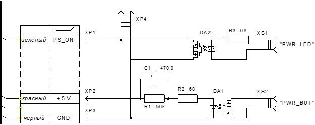
Without an electronic control device, nowhere. Terms of Reference: make the necessary conclusions on the PSU connector after they are short-circuited by the power button, apply the power-on signal to the motherboard (close the contacts by simulating the power button), keep the contacts on the PSU connector closed until the PC is turned off; the signal outputs of the PC are the terminals “PWR_LED” on the motherboard; PC shutdown is done by software. The task is defined, we take Arduino and, trying not to disturb the dust layer, we push it even further onto the shelf. With the titanic tension of thought processes, we create the following scheme of the “launch manager”:
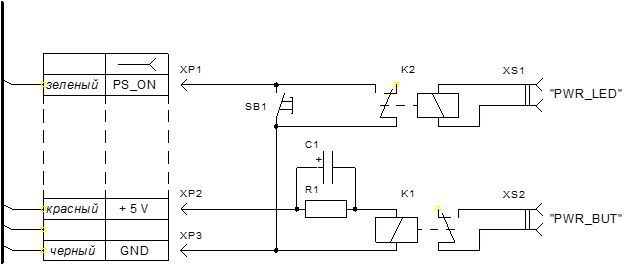
A brief description of the operation of the circuit: using the SB1 button, close the PS_ON output to GND and start the power supply. Through the chain R1C1, the pulse is fed to the relay K1 and it briefly closes the contacts “PWR_BUT” on the motherboard. The motherboard turns on, supplies power to its “PWR_LED” terminals, and the K2 relay connected to them reliably closes the terminals on the PSU connector (now the state of the SB1 button does not bother us). After the “Shut Down” command, the PC (motherboard) turns off, removes voltage from the “PWR_LED” terminals, and relay K2 opening the contacts turns off the power supply. The resistor R1 serves to discharge the capacitor C1 and its value should provide a reliable discharge of the capacitor. It is impossible to underestimate this value strongly, otherwise there is a possibility of a constant switching on of relay K1. This will lead to that.
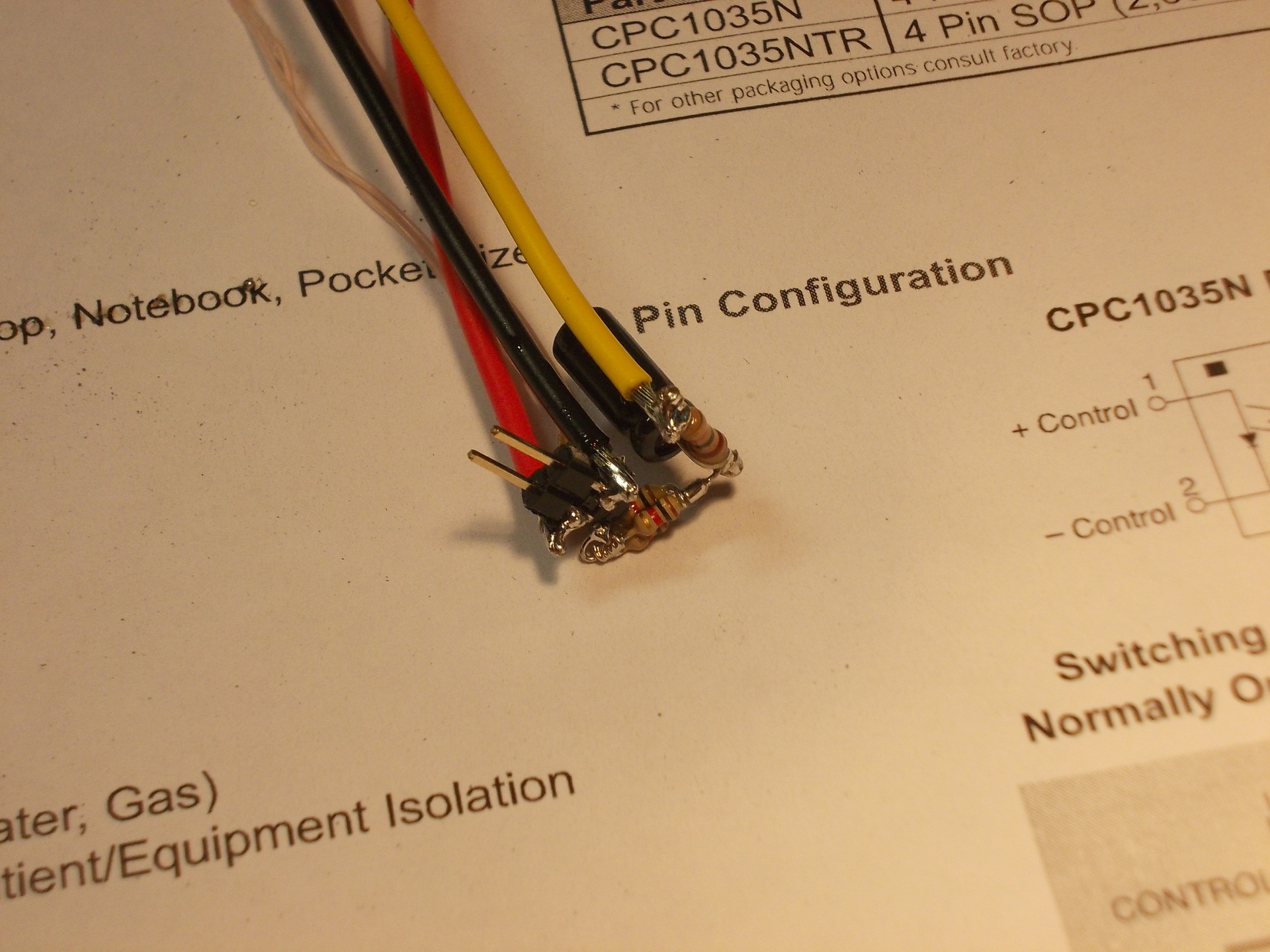
But living in the XXI century it is not serious to use relays: they click, consume a lot, have relatively large dimensions and with constant switching on, the core is magnetized (there is such a parameter - operating time, you yourself had to change the relay that generated this resource). Therefore, we take solid-state relays (optocouplers). At one time, I used PVG612 in the development, but to buy them myself for 600 rubles - the toad strangles. Therefore, I climbed into the online store of electronic components, turned on the “in stock” filter, sorted “by price increase” and successfully selected CRC1035 for experiments, at a price of 70 rubles. for the body.
Made the necessary changes / additions to the scheme and rushed ...
As they say: hurry up, make people laugh. SMD cases are poorly adapted for volume mounting, what turned out to be beautiful did not shine:
As mathematicians say: a beautiful formula is true. I didn’t like the look myself and a strong-willed decision was made to dig out a breadboard (and gnaw off a piece of it). It became very good: I
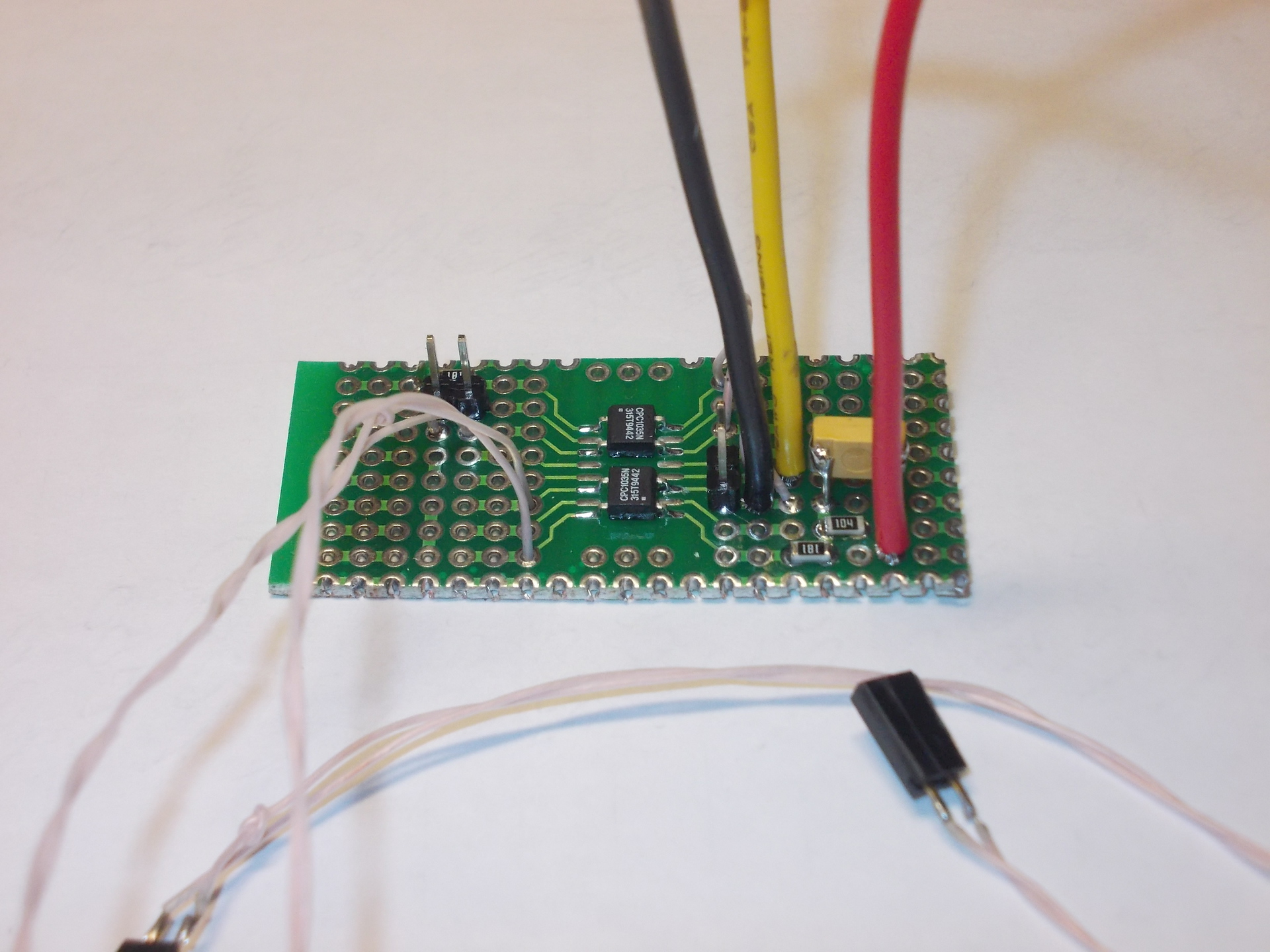
connected the assembled structure according to the scheme and now I enjoy the process. Everything works, nothing hangs from the case, beauty!
Because the power button is no longer connected to the motherboard, then we have lost the ability to force the PC to turn off if it freezes (long press and hold the button). Therefore, I added the “Reset” button that was missing on the case (I drilled a hole for a clip in the case and glued the button on the back with hot-melt adhesive). The “Power” indicator on the case connected to the +3.3 V terminals of the power supply (it is impossible to hang in parallel with the optocoupler - there will not be enough power for the optocoupler!). And once such a booze started, I fixed it on the case and connected the HDD operation LED to the motherboard.
The advantages of such an alteration include:
• the absence of an external power supply, which still consumes after shutting down the PC (ecology, concern for energy saving);
• the case allows you to install (in addition to slim-DVD) two 2.5 ”and one 3.5” HDD and the power of the built-in power supply unit is above the roof.
The result of the entire operation
Children single-handedly occupied a new computer, my wife squeezed out the free laptop, and I, having dug up an old laptop on the shelf (manufactured in 2000), sit in the kitchen and write this article ...
In the beginning there was a word , and then he got into a mess.
With longing, watching the growth of the exchange rate and the decrease in the assortment on the shelves, I made a strong-willed decision to replace the home laptop with a new PC desktop (and expropriate the free laptop for personal needs). After rummaging around "by the guts" in a personal household: monitor (was connected to the laptop as an external one), 2.5 ”500 GB HDD, 8 GB SO-DIMM DDR3 memory module. It remained for small - the motherboard, processor and case with power supply (keyboard and mouse were also available).
I personally like compact solutions (possibly due to limited work space) and the soul lies with mini-ITX standard motherboards. Graphics processing, video and "heavy" games are not fond of. therefore, I do not feel the need for a powerful discrete graphics card. In fairness, it should be noted that finding a regular video card in a "low" form factor is also a problem, but I am quite happy with the capabilities of the integrated video card. Earlier, three years ago, I assembled a NAS for home use based on a mini-ITX board with an Intel-Atom CPU installed. There were no special problems during assembly at that time, the device is working properly and is waiting for the expansion of the disk array (the selected case allows you to install 6 (six) HDDs 3.5 ”, there is an additional SATA controller board). Therefore, not expecting tricks, I proceeded to the selection of components.
The main limitation in the selection, in addition to the selected mini-ITX form factor, was the presence of a memory module of the SO-DIMM standard (for reference, this is the memory standard for laptops). A small caveat - in addition to laptops, this standard of memory modules is found only on mini-ITX boards and less. The soldered processor did not suit me much (with the expectation of further updating), so the LGA 1155 socket was chosen. As a result of selecting the price / availability / nearest store, we bought a Gigabyte GA-H61TN motherboard and a MiniITX Winsis WI-03 case with an installed 300 PSU Watt ATX standard. Here the ambush awaited!
I follow little changes and innovations in computer components. I heard about the desires to introduce a single +12 V power supply on the motherboards, but not as fast ... The purchased (and already installed in the case) motherboard had a “laptop” DC power connector and a two-pin ATX_19V connector. For a long time, with a dumb question in my eyes, I considered the wiring harness from the power supply and the motherboard: the choice is great, but there is nothing to stick in (there is nowhere). The first desire, to hand over the board and take another with the “correct” power connectors, was violently suppressed by the store staff. After a careful inspection of the board (with a magnifying glass!), Traces of mounting the board into the case were discovered and it was declared impossible to return. (Brief reference: tinned contact pads are located on the circuit board at the mounting holes around the circumference. When mounting the board, the screw head crushes the soft solder and a pronounced trace of “interference” remains. To eliminate installation traces, it is enough to cover the area with a flux and heat it with a hairdryer. The solder will melt and take its “original” form. The main thing is not to overheat (the traces of overheating can no longer be removed) and rinse off the flux residues (although traces of factory flux on the board are found in abundance)) By nature, I am not a scandalous person, “fat and lazy”. There was no desire to swear and delve into the laws, besides a sense of pride leaped up: I am not the manager of the trading floor, I am an engineer. In addition to the “fifth point”, from where many people grow their arms, and which often replaces the head, my head is out of place and my hands are sharpened correctly. The solution to technical problems is my bread! To eliminate installation traces, it is enough to cover the area with a flux and heat it with a hairdryer. The solder will melt and take its “original” form. The main thing is not to overheat (the traces of overheating can no longer be removed) and rinse off the flux residues (although traces of factory flux on the board are found in abundance)) By nature, I am not a scandalous person, “fat and lazy”. There was no desire to swear and delve into the laws, besides a sense of pride leaped up: I am not the manager of the trading floor, I am an engineer. In addition to the “fifth point”, from where many people grow their arms, and which often replaces the head, my head is out of place and my hands are sharpened correctly. The solution to technical problems is my bread! To eliminate installation traces, it is enough to cover the area with a flux and heat it with a hairdryer. The solder will melt and take its “original” form. The main thing is not to overheat (the traces of overheating can no longer be removed) and rinse off the flux residues (although traces of factory flux on the board are found in abundance)) By nature, I am not a scandalous person, “fat and lazy”. There was no desire to swear and delve into the laws, besides a sense of pride leaped up: I am not the manager of the trading floor, I am an engineer. In addition to the “fifth point”, from where many people grow their arms, and which often replaces the head, my head is out of place and my hands are sharpened correctly. The solution to technical problems is my bread! The main thing is not to overheat (the traces of overheating can no longer be removed) and rinse off the flux residues (although traces of factory flux on the board are found in abundance)) By nature, I am not a scandalous person, “fat and lazy”. There was no desire to swear and delve into the laws, besides a sense of pride leaped up: I am not the manager of the trading floor, I am an engineer. In addition to the “fifth point”, from where many people grow their arms, and which often replaces the head, my head is out of place and my hands are sharpened correctly. The solution to technical problems is my bread! The main thing is not to overheat (the traces of overheating can no longer be removed) and rinse off the flux residues (although traces of factory flux on the board are found in abundance)) By nature, I am not a scandalous person, “fat and lazy”. There was no desire to swear and delve into the laws, besides a sense of pride leaped up: I am not the manager of the trading floor, I am an engineer. In addition to the “fifth point”, from where many people grow their arms, and which often replaces the head, my head is out of place and my hands are sharpened correctly. The solution to technical problems is my bread!
The search for a solution to the problem has begun
After reading (!) The user manual for the motherboard, I found out, in addition to the type of connector, that the range of supply voltages is from 9 to 19 volts, and the recommended power supply of the power supply is 190 watts. From personal experience working with laptops from various manufacturers (Samsung, Asus, Acer, Sony, Lenovo), I know, there are different power connectors everywhere! It is frankly lazy to look for the correspondence of the type of connector indicated in the manual with any vendor. The use of a universal power supply for laptops is also not a solution: very often when changing the connector, you must follow the correct polarity of the connection, and there are no polarity information in the manual. And the last, I simply did not see the required power declared by the manufacturer in 190 watts in nature. The option with an external power supply dropped by itself.
Second step
The previously announced power range is also applicable to the ATX_19V connector on the board. We look at information on ATX power supplies, on output connectors in particular. And we find out that the four-pin auxiliary power connector for video cards (+12 V) is suitable for us. The polarity of the ATX_19V connector is indicated in the manual for the board, on the power supply unit an “earth” wire is black, +12 volt-yellow. The connectors have curly seats (but, if there is a force, the form is secondary), the latches match. The main thing is to connect correctly and not worry that the two legs of the connector hang in the air. But that’s not all, the power supply itself does not turn on. To do this, close the terminals “PS_ON” and “GND” on the 20/24 pin connector (green and black wires, respectively). This operation is carried out using a high-tech wire segment (connectors from the face muzzle of the case must be connected to the motherboard: power button and “Power” indicator). We press the power button and enjoy the result. After that, we fasten the switch and quickly proudly demonstrate the result of our work (a report to my beloved wife about the ruined day off).
As you know, this solution is far from ideal and does not paint the author as an engineer. In addition, a high probability of accidentally pushing the remote toggle switch by any member of the family, and especially by the cat, introduces a share of risk. It means stopping early, let's move on.
Step three
Without an electronic control device, nowhere. Terms of Reference: make the necessary conclusions on the PSU connector after they are short-circuited by the power button, apply the power-on signal to the motherboard (close the contacts by simulating the power button), keep the contacts on the PSU connector closed until the PC is turned off; the signal outputs of the PC are the terminals “PWR_LED” on the motherboard; PC shutdown is done by software. The task is defined, we take Arduino and, trying not to disturb the dust layer, we push it even further onto the shelf. With the titanic tension of thought processes, we create the following scheme of the “launch manager”:
A brief description of the operation of the circuit: using the SB1 button, close the PS_ON output to GND and start the power supply. Through the chain R1C1, the pulse is fed to the relay K1 and it briefly closes the contacts “PWR_BUT” on the motherboard. The motherboard turns on, supplies power to its “PWR_LED” terminals, and the K2 relay connected to them reliably closes the terminals on the PSU connector (now the state of the SB1 button does not bother us). After the “Shut Down” command, the PC (motherboard) turns off, removes voltage from the “PWR_LED” terminals, and relay K2 opening the contacts turns off the power supply. The resistor R1 serves to discharge the capacitor C1 and its value should provide a reliable discharge of the capacitor. It is impossible to underestimate this value strongly, otherwise there is a possibility of a constant switching on of relay K1. This will lead to that.
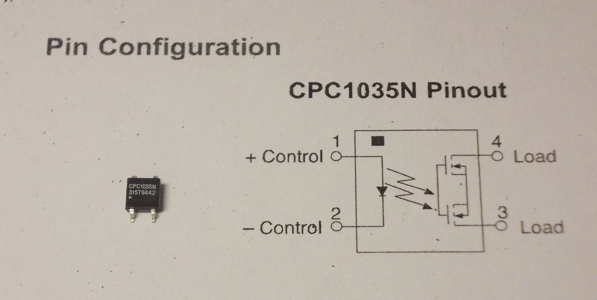
But living in the XXI century it is not serious to use relays: they click, consume a lot, have relatively large dimensions and with constant switching on, the core is magnetized (there is such a parameter - operating time, you yourself had to change the relay that generated this resource). Therefore, we take solid-state relays (optocouplers). At one time, I used PVG612 in the development, but to buy them myself for 600 rubles - the toad strangles. Therefore, I climbed into the online store of electronic components, turned on the “in stock” filter, sorted “by price increase” and successfully selected CRC1035 for experiments, at a price of 70 rubles. for the body.
Made the necessary changes / additions to the scheme and rushed ...
As they say: hurry up, make people laugh. SMD cases are poorly adapted for volume mounting, what turned out to be beautiful did not shine:
As mathematicians say: a beautiful formula is true. I didn’t like the look myself and a strong-willed decision was made to dig out a breadboard (and gnaw off a piece of it). It became very good: I
connected the assembled structure according to the scheme and now I enjoy the process. Everything works, nothing hangs from the case, beauty!
Because the power button is no longer connected to the motherboard, then we have lost the ability to force the PC to turn off if it freezes (long press and hold the button). Therefore, I added the “Reset” button that was missing on the case (I drilled a hole for a clip in the case and glued the button on the back with hot-melt adhesive). The “Power” indicator on the case connected to the +3.3 V terminals of the power supply (it is impossible to hang in parallel with the optocoupler - there will not be enough power for the optocoupler!). And once such a booze started, I fixed it on the case and connected the HDD operation LED to the motherboard.
The advantages of such an alteration include:
• the absence of an external power supply, which still consumes after shutting down the PC (ecology, concern for energy saving);
• the case allows you to install (in addition to slim-DVD) two 2.5 ”and one 3.5” HDD and the power of the built-in power supply unit is above the roof.
The result of the entire operation
Children single-handedly occupied a new computer, my wife squeezed out the free laptop, and I, having dug up an old laptop on the shelf (manufactured in 2000), sit in the kitchen and write this article ...