How to assemble an analog levitron yourself
0. Foreword
I read all kinds of Internet here and decided to make my own levitron, without any digital nonsense. No sooner said than done. I spread the pangs of creativity on public display.
1. Brief description
Levitron is a device that keeps an object in equilibrium with the forces of gravity using a magnetic field. It has long been known that it is impossible to levitate an object using static magnetic fields. In school physics, this was called the state of unstable equilibrium, as I recall. However, having spent a little desire, knowledge, effort, money and time, it is possible to levitate an object dynamically by using electronics as feedback.
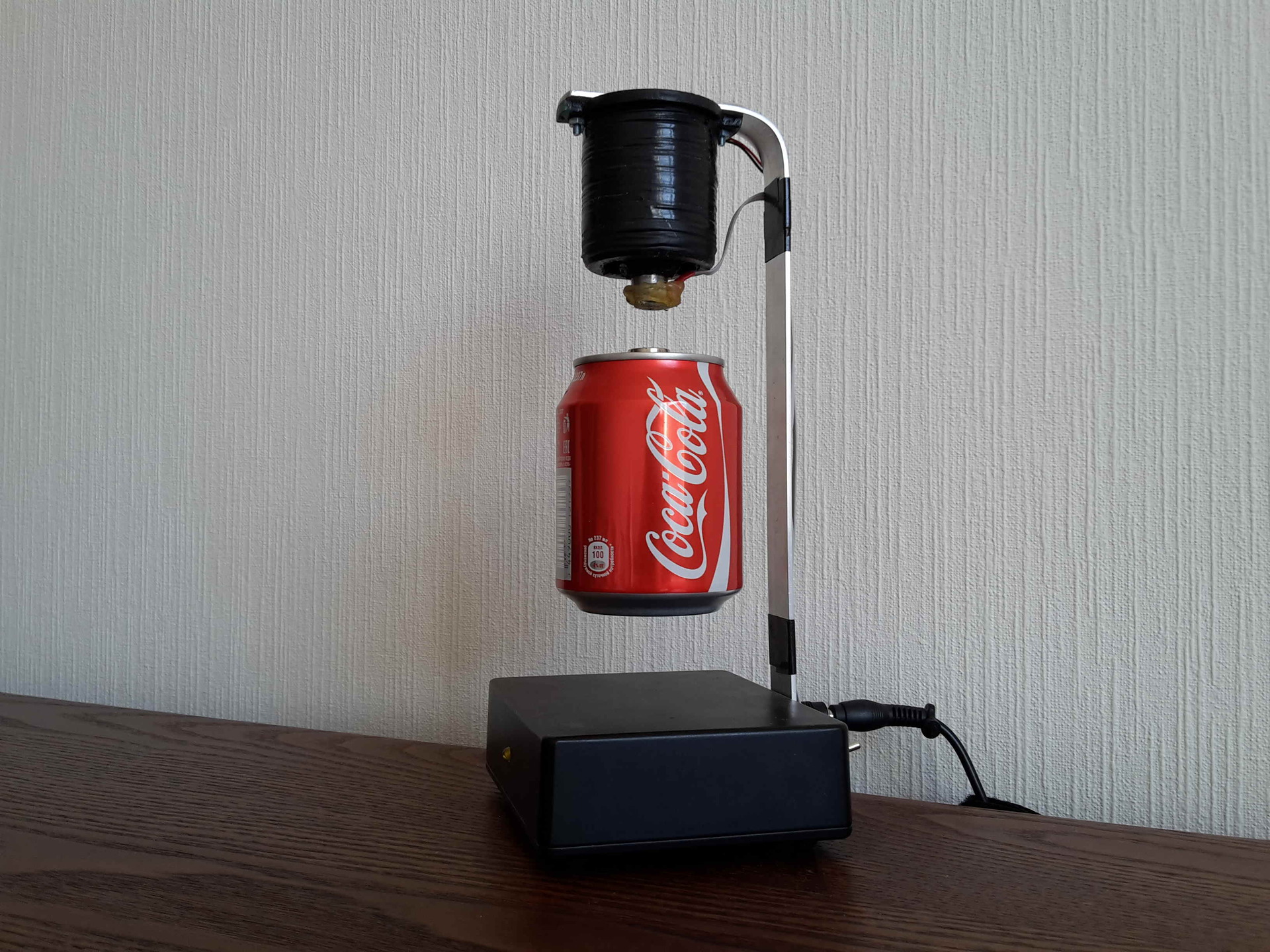
This is what happened:
2. Functional circuit

Electro-magnetic sensors located at the ends of the coil emit a voltage proportional to the level of magnetic induction. In the absence of an external magnetic field, these voltages will be the same regardless of the magnitude of the coil current.
If there is a permanent magnet near the lower sensor, the control unit will generate a signal proportional to the magnet field, amplify it to the desired level and transmit it to the PWM to control the current through the coil. Thus, feedback arises and the coil will generate such a magnetic field that will keep the magnet in equilibrium with the forces of gravity.
Something abstruse, everything turned out, I'll try differently:
- There is no magnet - the induction at the ends of the coil is the same - the signal from the sensors is the same - the control unit generates a minimum signal - the coil works at full power;
- They brought the magnet close - the induction is very different - the signals from the sensors are very different - the control unit gives the maximum signal - the coil turns off completely - no one holds the magnet and it starts to fall;
- Beckons falls - moves away from the coil - the signal difference from the sensors decreases - the control unit decreases the output signal - the current through the coil increases - the induction of the coil increases - the magnet starts to attract;
- attracts attracts - approaches the coil - the difference in the signals from the sensors increases - the control unit increases the output signal - the current through the coil decreases - decreases the induction of the coil - the magnet begins to fall;
- Miracle - the magnet does not fall and is not attracted - or rather, it falls and is attracted several thousand times per second - that is, a dynamic equilibrium arises - the magnet simply hangs in the air.
3. Construction
The main structural element is an electromagnetic coil (solenoid), which holds a permanent magnet with its field.
78 meters of enamelled copper wire 0.6 mm in diameter are tightly wound on a plastic frame D36x48, it turned out somewhere around 600 turns. According to calculations, with a resistance of 4.8 Ohms and a 12V power supply, the current will be 2.5A, power 30W. This is necessary to select an external power supply. (In fact, it turned out 6.0 Ohm, it was unlikely that they cut more wires, rather they saved on the diameter.) A
steel core from the door hinge with a diameter of 20 mm was inserted inside the coil. Sensors are fixed at its ends with hot-melt adhesive, which must be oriented in the same direction.
The coil with sensors is mounted on an aluminum strip bracket, which, in turn, is attached to the housing, inside which there is a control board.
On the case there is an LED, a switch and a power socket.
An external power supply unit (GA-1040U) is taken with a power reserve and provides current up to 3.2A at 12V.
As a levitating object, a N35H magnet D15x5 with a glued Coca-Cola can is used. I must say right away that a full can is not suitable, so we make holes at the ends with a thin drill, pour out a valuable drink (you can drink it if you are not afraid of shavings) and glue a magnet to the top ring.

4. The basic scheme

The signals from the sensors U1 and U2 are fed to the operational amplifier OP1 / 4, included in the differential circuit. The upper sensor U1 is connected to the inverting input, the lower U2 to the non-inverting one, that is, the signals are subtracted, and at the output OP1 / 4 we obtain a voltage proportional only to the level of magnetic induction created by the permanent magnet near the lower sensor U2.
The combination of elements C1, R6 and R7 is the highlight of this scheme and allows you to achieve the effect of complete stability, the magnet will hang like a ball. How it works? The constant component of the signal passes through the divider R6R7 and attenuates 11 times. The variable component passes through the C1R7 filter without attenuation. Where does the variable component come from? The constant part depends on the position of the magnet near the lower sensor, the variable part arises due to oscillations of the magnet around the equilibrium point, i.e. from a change in position in time, i.e. from speed. We are interested in the magnet being stationary, i.e. its speed was 0. Thus, in the control signal we have two components - the constant is responsible for the position, and the variable is responsible for the stability of this position.
Further, the prepared signal is amplified by OP1 / 3. Using a variable resistor P2, the necessary gain is set at the tuning stage to achieve equilibrium, depending on the specific parameters of the magnet and coil.
A simple comparator is assembled on OP1 / 1, which disables the PWM and, accordingly, the coil when there is no magnet nearby. A very convenient thing, do not remove the power supply from the outlet if you removed the magnet. The response level is set by a variable resistor P1.
Next, the control signal is supplied to a pulse width modulator U3. The output voltage range is 12V, the frequency of the output pulses is set by the values C2, R10 and P3, and the duty cycle depends on the level of the input signal at the DTC input.
The PWM controls the switching of the power transistor T1, and that, in turn, controls the current through the coil.
LED1 can not be set, but the SD1 diode is required, to drain excess current and avoid overvoltage at the moments when the coil is turned off due to the phenomenon of self-induction.
NL1 is our homemade coil, which is dedicated to a separate section.
As a result, in equilibrium mode, the picture will be something like this: U1_OUT = 2.9V, U2_OUT = 3.6V, OP1 / 4_OUT = 0.7V, U3_IN = 1.8V, T1_OPEN = 25%, NL1_CURR = 0.5A.
For clarity, I apply the graphs of the transfer characteristic, frequency response and phase response, and oscillograms at the output of the PWM and coil.


5. Selection of components
The device is assembled from inexpensive and affordable components. The WIK06N copper wire turned out to be the most expensive, for 78 meters WIK06N paid 1200 rubles, everything else taken together was much cheaper. There is generally a wide field for experiments, you can do without a core, you can take a thinner wire. The main thing to remember is that induction along the axis of the coil depends on the number of turns, the current along them and the geometry of the coil.
The SS496A analog Hall sensors with linear characteristics up to 840Gs are used as magnetic field sensors U1 and U2, this is the case for our case. When using analogs with a different sensitivity, you need to adjust the gain at OP1 / 3, as well as check for the maximum induction level at the ends of your coil (in our case with a core it reaches 500 G), so that the sensors do not enter into saturation at peak load.
OP1 is an LM324N quad operational amplifier. When the coil is off, it produces 20mV instead of zero at the 14th output, but this is quite acceptable. The main thing is not to forget to choose from a handful of 100K resistors closest to the actual nominal value for installation as R1, R2, R3, R4.
Denominations C1, R6 and R7 were chosen by trial and error as the most optimal option for stabilizing magnets of different calibres (N35H magnets D27x8, D15x5 and D12x3 were tested). The ratio R6 / R7 can be left as is, and the C1 value should be increased to 2-5 μF, in case of problems.
When using very small magnets, you may not have enough gain, in this case, cut the R8 rating to 500 Ohm.
D1 and D2 are ordinary rectifier diodes 1N4001, here any fit.
As a pulse-width modulator U3, the common TL494CN chip is used. The frequency of operation is set by the elements C2, R10 and P3 (according to the 20kHz scheme). The optimal range is 20-30 kHz, with a lower frequency, a coil whistle appears. Instead of R10 and P3, you can simply put a 5.6K resistor.
T1 is an IRFZ44N field effect transistor, it will fit any other of the same series. When choosing other transistors, you may need to install a radiator, focus on the minimum values of channel resistance and gate charge.
SD1 is a Schottky diode VS-25CTQ045, here I grabbed with a large margin, a regular high-speed diode is also suitable, but it will probably get very hot.
LED1 yellow LED L-63YT, here, as they say, to taste and color, you can set them more and more so that everything glows with multi-colored lights.
U4 is a 5V voltage regulator L78L05ACZ for powering sensors and an operational amplifier. When using an external power supply with an additional 5V output, you can do without it, but it is better to leave capacitors.

6. Conclusion
Everything turned out as planned. The device works stably around the clock, consumes only 6W. Neither the diode, nor the coil, nor the transistor are heated. I put a couple of photos and the final video:


7. Disclaimer
I am not an electronic engineer or a writer, I just decided to share my experience. Maybe something seems too obvious to you, but something is too complicated, but forgot to mention something at all. Do not hesitate to make constructive suggestions both for the text and for improving the scheme, so that people can easily repeat this if there is such a desire.