We output the remote signal from the car radio with an amplifier controlled by i2c
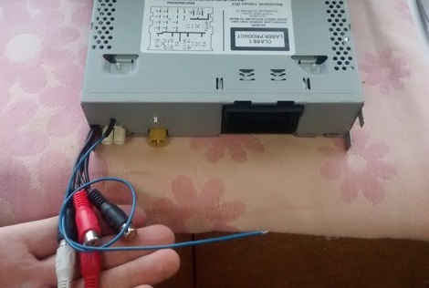
The REMOTE signal (12V voltage, which serves to turn on external amplifiers when the radio is turned on) is not so simple to derive from modern standard radio tape recorders. If earlier it was possible to use the ST-BY leg of an amplifier chip, now radio tape recorders do not use this leg because digitally controlled amplifier amplifiers have appeared.
You can search the circuit board for tracks on which voltage appears when the radio is turned on, but in most cases they are not suitable. You can connect to the power of the display backlight, only in this case the amplifier can turn on unscheduledly - before turning on the built-in amplifier (which is accompanied by clicks in the path) or when adjusting the climate or when the parking sensors are working.
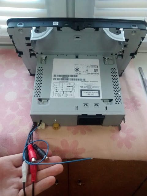
I will try to describe another way out of the situation on the example of the standard Swing radio on Skoda Octavia A7
We study the device
The terminal amplifier is TDA7563, an analog signal comes to it with the DSP SAF7741HV.
TDA7563, as it turned out, is very fond of the manufacturers of full-time radio receivers due to the fact that the microcircuit has digital control and diagnostics on the i2c bus, and i2c has been used in radio receivers for a very long time. The amplifier microcircuit, when the radio is turned on, at the command of the main processor, tests the speakers, gives the test result according to i2c - an open / short circuit is determined, which allows the radio unit to issue these errors via CAN diagnostic equipment. The amplifier’s microcircuit is also put into sleep mode by i2c commands (the ST-BY leg of the amplifier is not used), which greatly complicates the receipt of the REMOTE signal.
In general, the entire radio is constantly powered, regardless of whether it is turned on and the ignition on. It’s just that all unnecessary microcircuits (including the amplifier) are covered up until they are needed and the main processor of the radio tape recorder wakes them up (in our case).
The status of the inclusion of dimensions and the inclusion of ignition radio receives CAN. Exchange with steering wheel buttons - via CAN to the diagnostic bus gateway unit, then - via LIN to the button controller in the steering wheel.
Idea
The idea is to put another device based on a simple and cheap microcontroller on the internal bus of the i2c radio that will pretend to be an amplifier chip and listen to all the commands that fly into it from the radio's processor. Moreover, i2c allows our "spy" to remain invisible to the radio processor. The built-in amplifier will function as before, and the REMOTE signal will be generated by the microcontroller exactly when the radio turns on its built-in amplifier. This method is suitable for all radio tape recorders in which the TDA7563 chip is used or compatible with it via the exchange protocol.
The device itself was assembled on a weekend on a board on which, in addition to the microcontroller, there were only 3 resistors and 2 debug LEDs (optional). The microcontroller is picked up from an unnecessary device, so for a long time I did not think about choosing a micron.


Debug controller software
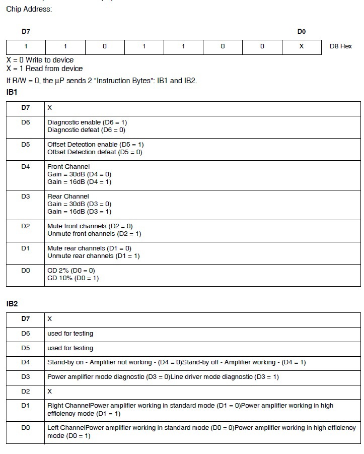
Everything is quite simple. We just need to implement i2c-slave with an address like TDA7563 (0x6C) and wait for write requests. Next, you need to take 2 Instruction byte from the processor of the radio and analyze them. The bits of interest are Standby Off in byte IB2, Unmute Rear Channels and Unmute Front Channels in byte IB1. In general, it turned out that the radio tape recorder first sets the Standby Off bit and with a slight delay - the Unmute Front Channels and Unmute Rear Channels bits.
I described command bytes in the form of bit structures, which I put in a union together with an array of 2 bytes, so that when filling the buffer, it would be accessed byte-by-bye, and when parsing the command, I would have convenient access to the bits:
Command Receive Buffer Description
typedef struct
{
unsigned char CD_10: 1;
unsigned char UnmuteRearChannels: 1;
unsigned char UnmuteFrontChannels: 1;
unsigned char RearChannelGain12db: 1;
unsigned char FrontChannelGain12db: 1;
unsigned char OffsetDetectionEnable: 1;
unsigned char DiagnosticEnable: 1;
unsigned char NotUsed1: 1;
} tIB1;
typedef struct
{
unsigned char HighEfficiencyMode_Left: 1;
unsigned char HighEfficiencyMode_Right: 1;
unsigned char CurrentDetectionDiagnosticEnable: 1;
unsigned char LineDriverModeDiagnostic: 1;
unsigned char StandbyOff: 1;
unsigned char FastMuting: 1;
unsigned char NotUsed1: 1;
unsigned char NotUsed2: 1;
} tIB2;
typedef union
{
struct
{
tIB1 IB1;
tIB2 IB2;
} IBs;
char Bytes [2];
} tTWI_Buff;
{
unsigned char CD_10: 1;
unsigned char UnmuteRearChannels: 1;
unsigned char UnmuteFrontChannels: 1;
unsigned char RearChannelGain12db: 1;
unsigned char FrontChannelGain12db: 1;
unsigned char OffsetDetectionEnable: 1;
unsigned char DiagnosticEnable: 1;
unsigned char NotUsed1: 1;
} tIB1;
typedef struct
{
unsigned char HighEfficiencyMode_Left: 1;
unsigned char HighEfficiencyMode_Right: 1;
unsigned char CurrentDetectionDiagnosticEnable: 1;
unsigned char LineDriverModeDiagnostic: 1;
unsigned char StandbyOff: 1;
unsigned char FastMuting: 1;
unsigned char NotUsed1: 1;
unsigned char NotUsed2: 1;
} tIB2;
typedef union
{
struct
{
tIB1 IB1;
tIB2 IB2;
} IBs;
char Bytes [2];
} tTWI_Buff;
And this is how the command check looks (I check the Standby Off and Unmute Front Channels bits):
The code
void CheckTWIbuff (void)
{
if ((TWI_Buff.IBs.IB2.StandbyOff) && (TWI_Buff.IBs.IB1.UnmuteFrontChannels))
REMOTE_ON ();
else
REMOTE_OFF ();
}
{
if ((TWI_Buff.IBs.IB2.StandbyOff) && (TWI_Buff.IBs.IB1.UnmuteFrontChannels))
REMOTE_ON ();
else
REMOTE_OFF ();
}
To prevent the spy from interfering with reading the state from TDA7563, we will issue bytes = 0xFF during read operations from the slave, so that the TDA can draw the SDA line to the ground at the right moments and the spy does not interfere with it.
I2c interrupt handler
#pragma vector = TWI_vect
__interrupt void TWI_ISR ()
{
switch (TWSR & 0xF8)
{
// === Data transmission
case 0xa8: // Your address is accepted, a receipt is issued, Data will be returned.
case 0xb8: // Data byte issued, ACK received.
case 0xc0: // Data byte issued, NACK received.
TWDR = 0xFF;
break;
// === Receive data
case 0x60: // Received your address, issued a receipt, will receive Data.
TWI_Buff_Idx = 0;
LED_Flash (5000);
break;
case 0x80: // Data byte received, receipt issued.
case 0x88: // Data byte received, receipt not issued.
TWI_Buff.Bytes [TWI_Buff_Idx ++] = TWDR;
break;
case 0xa0: // Upon receipt, STOP or RESTART was received at its address.
CheckTWIbuff ();
break;
case 0xF8:
case 0x00:
Init_Twi ();
break;
default:
break;
}
TWCR | = (1 << TWINT); // Clear the interrupt flag.
}
The whole project can be downloaded from here . In principle, the code is easily redone for any ms amplifiers with i2c control. (met TDF8546, for example).
My controller sleeps 99% of the time in Power-down mode. Wakes up when accessing its i2c address (using hardware TWI), accepts a command, analyzes it, if necessary outputs 1 to the output REMOTE_3.3, blinks the second debugging LED (D2) and falls asleep again.
Debugging process:
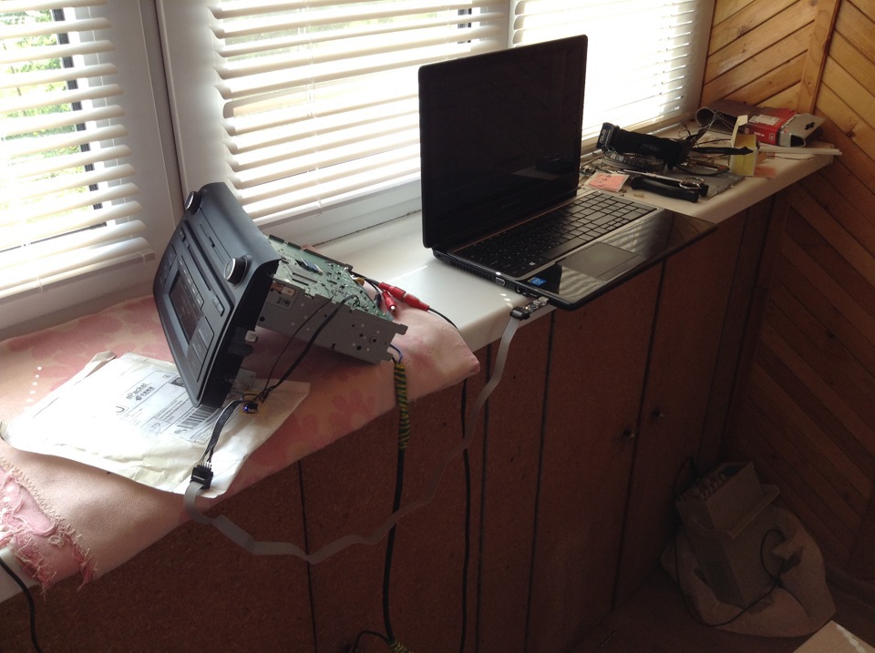
We collect
When the firmware is debugged, you can start assembling the radio.
Fee I glued to the screen tuner:
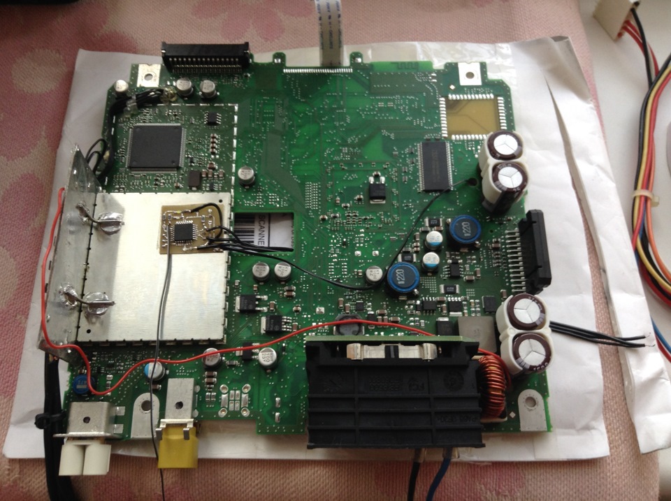
Because I didn’t have a place for transistors on the board, forming a 12V voltage from the REMOTE_3.3 controller, I just took 78R12 controlled by the logic level. Also added an integrated fuse N10 at 0.4A.

TDA7563 connected to the i2c bus of the radio on the legs: The radio

has been assembled. The coveted blue posting
The same, but on a different radio and in video format: