May 26, 2015 at 10:40
Overview of the startup device "Autostart", analysis and testing

There was an opportunity here to carry out a review of the compact launcher "Autostart". Calling it in plain language: portable battery, power bank. Allows you to charge your phone / tablet, and in case of urgent need to start the car engine.
It is delivered in a neat “gift” box, and the package includes, in addition to the device itself, three different cables: a bank charging cable from a car cigarette lighter, a car charging cable from a bank connector, and a cable for powering the USB peripherals.
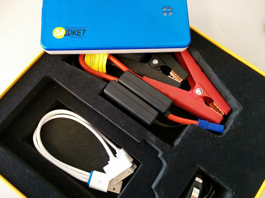
Let's start from afar, with a cigarette lighter cable. 10 AWG wires in silicone insulation are used, flexible and powerful, wires of this type are actively used by modellers in electric aircraft-auto models. In this case, 10 AWG is 5.26 mm² of copper, which allows 333A to be carried out at intervals of up to ≈10 seconds.
Two “black boxes” hang on the wires, and it will be logical to examine them.
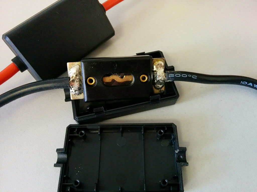
Black box on the positive wire: assembly of Schottky diodes 42CTQ030. Each case is two diodes, the total recommended current per case is up to 40A for continuous operation, or 1100A in a pulse of 3 μs. In this case, 3 cases are installed, it is 120A constantly, or 3300A in a pulse. It should be understood that continuous use under such currents is not assumed, therefore, there is no heat sink.
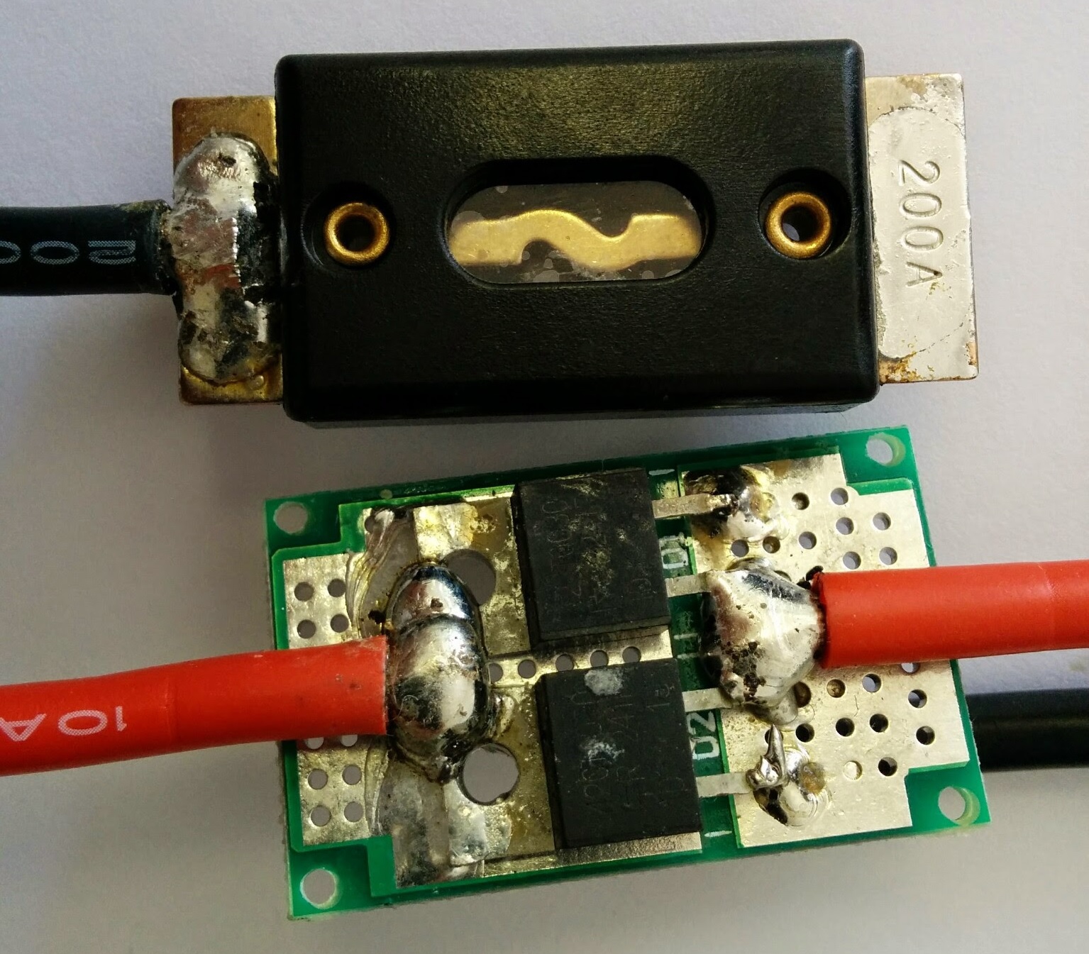
Black box on negative wire: fuse, unlabeled. A more detailed examination led to traces of coinage on the contact under one of the rations. Under the wire and a layer of solder, the figure 200A is hidden. This is the burn-out current during relatively long operation - the flowing current must have time to warm up the conductor, the warm-up time is determined by the current in the circuit, and the current is determined by the resistance. The internal resistance of modern lithium-polymer batteries is measured in units of mOhm, conventionally ≈1 mOhm per cell, in this case three cells are used. The wire resistance is ≈3.27 mOhm per meter, in this case it gives ≈1.5 mOhm (~ 40 cm of wires). The resistance of the diodes is 6.76 mOhm per assembly, with a parallel connection of three, 2.25 mOhm is obtained. The total resistance is 6.75 mOhm, which gives a short-circuit current of 1777A.
From the side connected to the Power Bank, the EC5 connector, familiar to modelers, and with a permissible continuous current of more than 120 A, is soldered to the wire, I could not find the upper limit on this connector, but the numbers appear on the forums at 210A @ 12V for prolonged operation.
On the battery side of the car, two crocodiles are soldered. I did not find any weaknesses, the wires were everywhere soldered and crimped securely, no complaints.
We turn to the main object of study. A brick with a blue lid, the size of an average smartphone. In the area of the four connectors, there is a sectional indicator showing the battery charge, from the front of the power (EC5) connector for power transmission to a lead car battery, a cigarette lighter cylindrical connector (14 v), a flashlight LED, micro-USB for charging from a PC, USB type A to transfer energy to arbitrary peripherals. On one side there is a single button, a power button.

Being in the off state, the battery voltage is present at the power terminals, and here the first alarming note arises. In a good way, you need a plastic / silicone plug so that the connector in the backpack / pocket is not accidentally closed, because there are no fuses inside the device, and in this case the device can burn out well. Lithium polymer batteries with large discharge currents burn well when closed, hundreds of evidence can be found on YouTube.
The case consists of two parts, conventionally “pallet” and “cover”, the parts are glued together around the perimeter, and opening such a case without serious need is not recommended - the presentation will definitely be damaged, the warranty will definitely be lost, the strength and reliability will also not be higher .
But I'm interested in a review of the internal contents: the device device, the circuitry of the charger, the characteristics of the DC / DC converters, the protection circuit, the control circuit and charge measurement. All this will require some sacrifice.
For those who need to disassemble this case - be careful not to damage the battery when using sharp tools when opening - inaccurate penetration into the case to a depth of more than 2 mm can cut through the thin shell of the battery and short out the internal lamellas. This can be fatal.
Excellent, an autopsy showed that the patient did not die as a result of the autopsy, you can continue the review. Two-thirds of the device is occupied by a battery consisting of three series-connected elements, the rest of the space is reserved for electronics. The battery without identification marks, with electronics all more transparent.
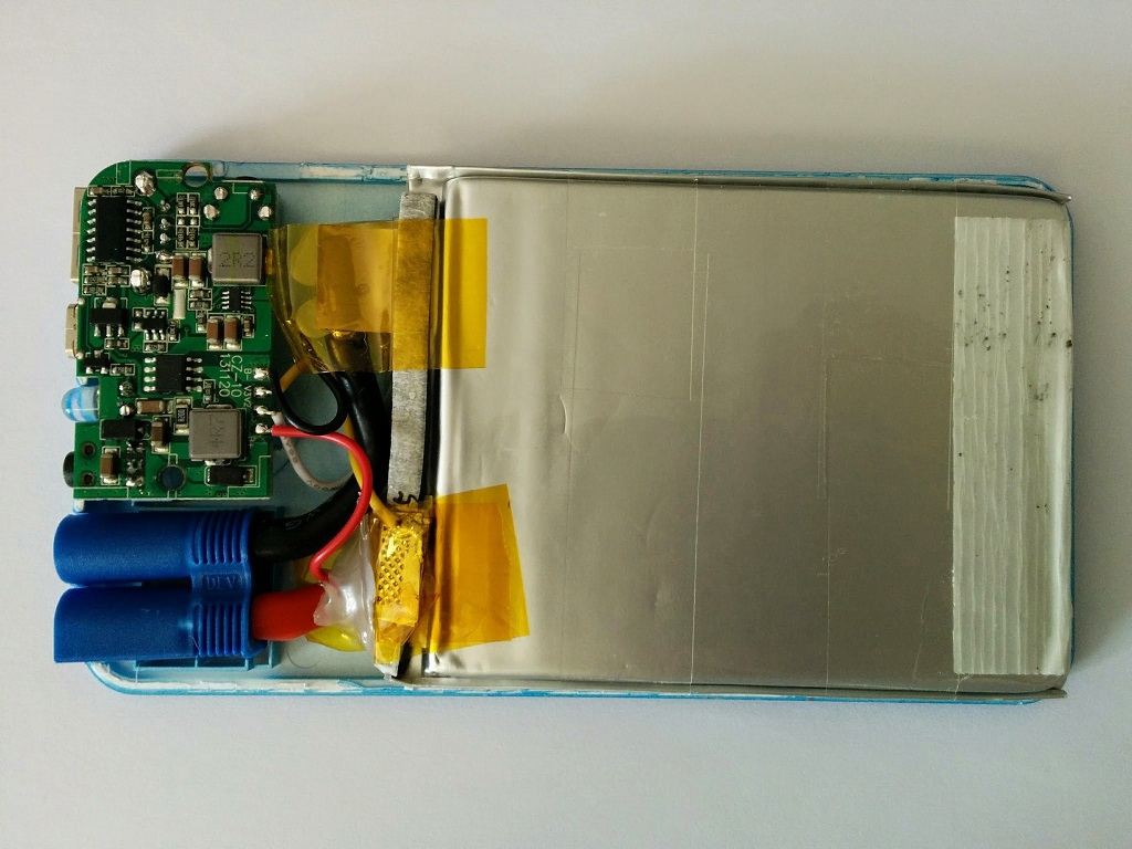
Let's deal with electronics. Charge Controller Board Double-sided mounting, four-layer design, tightly and compactly spaced components. Let's try to restore the structural diagram.
Front side:
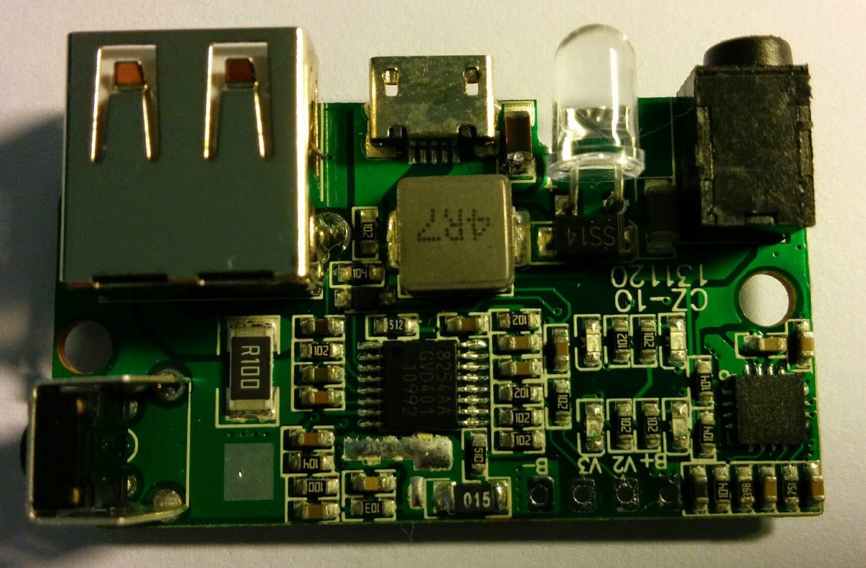
Square MP26123 (QFN16): charger, accepts up to 24 volts input, charges batteries of 2 or 3 cells. In fact, it is a pulsed DC / DC converter, with an adjustable charge current, with feedback on current and voltage (while the voltage on the battery is below 12.6V - charging is performed by the current, as soon as the voltage reaches the setting - charging continues with voltage). Working solution.
Rectangular S-8254A (16-pin TSSOP): battery monitor, monitors the voltage on all cells of the battery (overdischarge, overcharge), monitors currents (load disconnection when current is exceeded).
The choke marked 4R7 and the Schottky diode SS14 next to micro USB belong to the boost converter 5V → 14V, which allows you to charge the power bank from USB. And on the little things: the power button, next to it is a current shunt, for tracking the supplied current, a USB connector, by which the current is actually delivered, a microUSB connector for charging the bank from 5V, a flashlight LED, and a connector for a cylindrical plug, for charging the bank from 14V.
Back side:

The inductor marked 4R7 and the Schottky diode SS14 belong to the charger.
The eight-legged beetle in the SO-8 case is a dual P-FET AM4915P, for disconnecting the load in case of exceeding the current consumption, and for turning off the controller in case of a deep discharge of the battery.
Three-legged HT7550-1 - low drop out linear regulator. Regulator to power the controller.
The controller nearby, in the SO-14 case, without marking, is one of many Chinese microcontrollers that can turn on, turn off and blink LEDs.
Choke marked 2R2 and an octopus beetle nearby - DC / DC converter from 12V to 5V
Six-legged small in the center - StepUP, increasing from 5V to 14V for charging from microUSB.
So, there is protection against overdischarge of the battery, from short circuit on the 5V line, there is charging from 5 volts, from 14 volts, there is a controller that measures the charge level, indicating it to a group of LEDs, there is a flashlight, and all this is quite neatly packed on a 20x30mm board .
There is a minor gripe. To voice it, you need an excursion into a separate topic.
There is a class of so-called “Smart” chargers, well familiar to modelers, are almost all chargers for lithium-polymer batteries with balancing sockets. Their intelligence consists in controlling the voltages on each element of the battery and balancing these voltages.
It’s quite an important point, since with a slight undercharging / overcharging of elements during subsequent work under heavy load, the so-called “unbalance” will occur, i.e. some battery cells will be discharged faster than their "counterparts", which will begin to cause their degradation, and subsequent death.
It is impossible to completely get rid of the imbalance, each element is individual, and has its own internal resistance, its own capacity.
Therefore, the only way to solve the problem is to equalize the voltage in the battery with each charge.
The charger monitors and corrects this imbalance with every charge, which helps increase battery life.
So, in this case, I did not see the balancing scheme. As I understand it, Power Bank is not a product where the manufacturer will put another ≈20 elements that perform balancing. But in this case, this scheme would be useful.
In general, the board is assembled on modern components, all pulse converters operate at a frequency of 1 MHz (only a charger at 600 KHz, but it can), and the build quality is not satisfactory.
The next part of the review. Battery.
What interested me was that the characteristics on the back of the bank were imprinted: 6000 mAh / 22 Wh. And here lies the first strangeness. From physics, P [Watt] = I [Ampere] * U [Volt].
The “standard” voltage on the battery of 3 cells is 11.1 volts.
22 W / 11.1 Volts ≈ 2000 mA
Hm, 2000 mAh does not look like 6000 mAh, even with rounding. And what does it really cost?
I will check on the charger Hyperion EOS 0606i. I solder the balancing connector to the battery, charge with balancing and start the discharge with a current of 300 mA. According to the test results, the battery shows a capacity of ≈2000 mAh.
The only conjecture that arises in the head is that the 6000 mAh indicated by the manufacturer are “reduced” to a voltage of 3.7 volts. Those. if your phone has a 2000 mAh battery, then, theoretically, with this bank you can charge 3 times. In practice, there are losses in the DC / DC converters that will worsen the result, but in general the logic of the manufacturer is clear.
So, with the device’s device, everything is clear, go to the next part. Device tests.
5V line load power

To check the overload and overdischarge protection schemes, a load simulator was assembled from a series of 16Ω 10W resistors and an ammeter in parallel assembled. Stable operation was observed at currents up to 2.3A (8 resistors), while the temperature on the throttle reached 66 ° C, the temperature on the DC / DC chip of the controller was 80 ° C, and the voltage at the converter output went down to 4.6V. If the current exceeds 2.4A, the power monitor stably disconnects the DC / DC converter. During discharge, the microcontroller extinguishes the indicator LEDs in accordance with the remaining battery capacity. When the battery voltage is 9.6V (3.2V), the controller disconnects the load. Everything is within normal limits, although a residual 3.2V per cell is not enough.
Charging from 14 volts
I used an adjustable power source for verification. Charging a fully discharged bank is possible from a voltage of 12V, but above the input voltage, in this case, it will not work. Yes, this is not SEPIC. In general, the battery is charged with a current of 1A, regardless of the input voltage, and lasts, on average, for two hours. In the range from 12 to 20 volts, there were no problems with operation. During charging, the luminous indicators display the current charge level, and the blinking one indicates the process itself, gradually, as the charge progresses, moving in a circle. For the entire charging time, one revolution is performed.
As an option to increase usability - change the duty cycle of flashes as the charge.
0% - short flashes of the first diode, all others are extinguished;
99% are long flashes of the last diode, all the rest are on.
Charging from 5 volts
In this case, a step-up DC / DC converter is turned on, which increases from 5 to 14 volts, and supplies this voltage to the 14V connector. Yes, voltage is present on the barrel connector while charging from micro USB. It even works from 2V, the current consumption is 200 mA, it is clear that charging in this case will last 30 times longer, but, nevertheless, the very ability to charge at least from the "potato battery" pleases.
At an honest 5 volts, the converter starts to consume 2A, heats up to 80 degrees, but, nevertheless, continues to work. In this mode, charging lasts a little over 2 hours.
That’s probably all
The bank looks quite reliable and complete device, quite neat and thought out. There is only one gripe: battery capacity. Firstly, in the midst of modelers it is customary to write the actual capacity, not the one given, and secondly, the actual capacity in this device is not enough.
The ability to directly remove the 11.1V battery, with maximum current output, is also a positive point. I didn’t have a car with a discharged battery at hand, but I understand that it’ll work. Third-party reviews confirm.
In conclusion, I can recommend " Autostart " as a gift - excellent appearance, excellent packaging, and guaranteed operation. Everyone will be happy with a gift with such functions.