STM32F103C8T6 - make an oscilloscope. Part 3
The third part ( first and second ) about how I make an oscilloscope from a debug board for less than $ 3. Demo video of work:
A description of some key features under the cut.
Almost everything as described in the second part , except for the bipolar power source. The opamps consume a significant current (of the order of 10 mA), and as they did not try to obtain acceptable results with the voltage multiplier circuits on the diodes and capacitors, they failed. Therefore, for a positive voltage, I put here such a module based on MT3608:
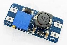
tuned to 10 V of the output voltage. And I get a negative voltage by inverting the positive with LT1054.
In the first part I wrote that a lot of memory is consumed. Now I got to the point that the program does not fit into the memory and studied this issue in more detail.
CooCox CoIDE displays information about the size of the program as follows:
Where
The whole program takes:
Now let's see what memory is wasted on. We make a new project and compile:
To use macros like GPIO_BSRR_BS9, you need to include the stm32f10x.h file.
To connect the stm32f10x.h file, you need to add the STM32F10x_MD_STDLIB component in the repositories, which pulls cmsis_core along with it. As a result, for a program that writes one value to the register, we get:
Next, I'm interested in functions like sprintf and sscanf. To use them, you need to define some functions like _sbrk and possibly some others. I took the finished file (there is in the archive with the project). Add 1 call to sscanf and get:
Implemented 3 modes according to the principle of operation: continuous, batch and logical, and 3 according to the number of channels: 1, 2 and 4 channels.
MK has 9 analog inputs, but I can not imagine when I may need more than 4 channels.
Everything is simple here: in the main MK loop, we read the ADC data and transfer it to a PC, where we can build a continuous graph. The disadvantage is the speed limit on the side of the MK -> PC channel. To get around it, I implemented 2 more modes.
In this mode, MK first collects data, then transfers it to a PC with a bundle. It can optionally be overclocked. I wrote about acceleration in detail in the previous parts.
In this mode, synchronization is possible. Moreover, you can analyze the signal until the condition is met. To implement this functionality, it was necessary to change the DMA operating mode on the ring, use half-buffer interruption and use a buffer containing 2 times more data than in the transmitted packet.
Unlike the baghear project , I have a software trigger. The advantages of this solution:
In single-channel mode, both ADCs in turn convert the value of one channel.
In two-channel mode, each ADC converts its channel by starting simultaneously with the other.
In the 4-channel - each ADC has 2 channels that it converts. The start of both ADCs is simultaneous.
Obviously, the speed of the channel conversion frequency is inversely proportional to the number of channels.
The fastest mode. Approximately 20 MSPS on each channel. The fastest code for this mode looks like this:
and so on for the entire buffer.
The value of the variable i in this case is calculated at the compilation stage and, as a result, from dataBuffer.u8 [++ i] = GPIOA-> IDR; it turns out only 2 operations - load the data into the register from the port and save the data to memory at a pre-calculated address. It was not possible to achieve such performance in any cycles.
The main, in my opinion, change is the transition to OpenGL. With it, drawing graphics became easier (for me it was unexpected, but everything is really simple and concise!), They are drawn faster and turn out to be much more beautiful than they were before.
The project is not completed, there are glitches, to finish a lot of things, but any breakthroughs are no longer expected. For faster systems, you need other hardware, for example, a separate ADC + FPGA + memory - and this will already be much more expensive and more difficult to mount. After reading the
comments on the article "The history of one oscilloscope on stm32" I will immediately answer some questions:
Archive with the project
If anyone has questions, but is not registered here, write to the mail: adefikux on gmail dot com.
A description of some key features under the cut.
Analog part
Almost everything as described in the second part , except for the bipolar power source. The opamps consume a significant current (of the order of 10 mA), and as they did not try to obtain acceptable results with the voltage multiplier circuits on the diodes and capacitors, they failed. Therefore, for a positive voltage, I put here such a module based on MT3608:
tuned to 10 V of the output voltage. And I get a negative voltage by inverting the positive with LT1054.
About code size
In the first part I wrote that a lot of memory is consumed. Now I got to the point that the program does not fit into the memory and studied this issue in more detail.
CooCox CoIDE displays information about the size of the program as follows:
      text	   data	    bss	    dec	    hex	filename
     60224	   2500	  10540	  73264	  11e30	projectName.elf
Where
- text - the size of the segment with code, interrupt vectors and read-only constants;
- data - segment size with non-zero initialized variables;
- bss - segment size with uninitialized and zero-initialized variables.
The whole program takes:
- flash - text + data + 10..50 bytes
- RAM - data + bss + 10..50 bytes
Now let's see what memory is wasted on. We make a new project and compile:
      text	   data	    bss	    dec	    hex	filename
       364	   1080	     32	   1476	    5c4	test-size.elf
To use macros like GPIO_BSRR_BS9, you need to include the stm32f10x.h file.
To connect the stm32f10x.h file, you need to add the STM32F10x_MD_STDLIB component in the repositories, which pulls cmsis_core along with it. As a result, for a program that writes one value to the register, we get:
      text	   data	    bss	    dec	    hex	filename
      1316	   1104	     32	   2452	    994	test-size.elf
Next, I'm interested in functions like sprintf and sscanf. To use them, you need to define some functions like _sbrk and possibly some others. I took the finished file (there is in the archive with the project). Add 1 call to sscanf and get:
Try to guess how many before you watch!
41 kB flash! More than half of what is in the controller!
In the working firmware, when using printf, adding sscanf increases the flash consumption by 13.2 kB. As a result, sscanf refused, and PC commands began to be parsed by a less resource-intensive method.
The rejection of printf saves another 8.3 kB.
      text	   data	    bss	    dec	    hex	filename
     39312	   2264	     96	  41672	   a2c8	test-size.elf
41 kB flash! More than half of what is in the controller!
In the working firmware, when using printf, adding sscanf increases the flash consumption by 13.2 kB. As a result, sscanf refused, and PC commands began to be parsed by a less resource-intensive method.
The rejection of printf saves another 8.3 kB.
Operating modes
Implemented 3 modes according to the principle of operation: continuous, batch and logical, and 3 according to the number of channels: 1, 2 and 4 channels.
MK has 9 analog inputs, but I can not imagine when I may need more than 4 channels.
Continuous
Everything is simple here: in the main MK loop, we read the ADC data and transfer it to a PC, where we can build a continuous graph. The disadvantage is the speed limit on the side of the MK -> PC channel. To get around it, I implemented 2 more modes.
Batch
In this mode, MK first collects data, then transfers it to a PC with a bundle. It can optionally be overclocked. I wrote about acceleration in detail in the previous parts.
In this mode, synchronization is possible. Moreover, you can analyze the signal until the condition is met. To implement this functionality, it was necessary to change the DMA operating mode on the ring, use half-buffer interruption and use a buffer containing 2 times more data than in the transmitted packet.
Unlike the baghear project , I have a software trigger. The advantages of this solution:
- Fewer parts, which means less price and easier installation;
- The ability to implement more complex triggers in the future, and not just “the signal in the A channel has become larger than X”.
In single-channel mode, both ADCs in turn convert the value of one channel.
In two-channel mode, each ADC converts its channel by starting simultaneously with the other.
In the 4-channel - each ADC has 2 channels that it converts. The start of both ADCs is simultaneous.
Obviously, the speed of the channel conversion frequency is inversely proportional to the number of channels.
Logic analyzer
The fastest mode. Approximately 20 MSPS on each channel. The fastest code for this mode looks like this:
u32 i = 0;
dataBuffer.u8[i] = GPIOA->IDR;
dataBuffer.u8[++i] = GPIOA->IDR;
dataBuffer.u8[++i] = GPIOA->IDR;
dataBuffer.u8[++i] = GPIOA->IDR;
dataBuffer.u8[++i] = GPIOA->IDR;
dataBuffer.u8[++i] = GPIOA->IDR;
and so on for the entire buffer.
The value of the variable i in this case is calculated at the compilation stage and, as a result, from dataBuffer.u8 [++ i] = GPIOA-> IDR; it turns out only 2 operations - load the data into the register from the port and save the data to memory at a pre-calculated address. It was not possible to achieve such performance in any cycles.
PC program
The main, in my opinion, change is the transition to OpenGL. With it, drawing graphics became easier (for me it was unexpected, but everything is really simple and concise!), They are drawn faster and turn out to be much more beautiful than they were before.
Total
The project is not completed, there are glitches, to finish a lot of things, but any breakthroughs are no longer expected. For faster systems, you need other hardware, for example, a separate ADC + FPGA + memory - and this will already be much more expensive and more difficult to mount. After reading the
comments on the article "The history of one oscilloscope on stm32" I will immediately answer some questions:
- I’m not going to fasten the display because:
- It costs money, but there is a comp.
- The quality will be worse than on a large PC screen.
- Creating and changing a user interface in C # is easier than soldering and soldering.
- I do not plan to bring it a commercial product and sell it.
- He did it for 2 purposes: to master MK and make himself a digital oscilloscope.
Archive with the project
If anyone has questions, but is not registered here, write to the mail: adefikux on gmail dot com.