February 13, 2016 at 16:20
Serial computer "Arrow"
"Arrow" - the first-generation Soviet computer, which was one of the first domestic computers. The chief designer was Yuri Yakovlevich Bazilevsky, and his deputy was Bashir Iskandarovich Ramaev. The computer "Strela" belonged to the class of large machines with a highly developed and logically complete structure. This provided greater performance in solving complex and cumbersome tasks in terms of volume. In addition, the "Arrow" was also the first-born among the machines manufactured by the industry in series. The preceding models were made in single copies.
In the early 50's. B.I. Rameev began the development of a conceptual design of a digital electronic computer. After consideration by the technical advice of SKB-245, the scientist's project was approved. It is noteworthy that this happened on the first day the future chief designer of the machine Yu.Ya. went to work. Bazilevsky, appointed head of the department of digital machines SKB-245.
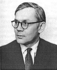
Bashir Iskandarovich Rameev (1918 - 1994) - Soviet scientist-inventor, developer of the first Soviet computers (Strela, Ural-1). Doctor of Technical Sciences. Laureate of the Stalin Prize.
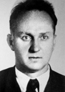
Yuri Yakovlevich Bazilevsky(1912 - 1983) - Soviet scientist, chief designer of the Strela computer and the automated computer complex for the Dal-111 air defense system. He was a hero of Socialist labor, laureate of the Stalin Prize.
The Strela computer development team consisted of specialists: chief designer Yu.Ya. Bazilevsky, deputy. chief designer B.I. Rameeva, designers G.M. Prokudaeva A.M. Litvinova, D.A. Zhuchkova, A.V. Shileyko, main performers A.P. Tsygankina, NB Trubnikova, B.F. Melnikova, G.D. Monakhova, I.F. Lygina, L.A. Larionova, A.M. Larionova, E.T. Semenova and others.
In the late 40s - early 50s. SKB-245 was created on the basis of the Moscow factory of calculating and analytical machines (CAM). This abbreviation was deciphered as a special design bureau for the development and support of the manufacture of computer equipment and military control systems. The organization had 6 departments, which were designated by numbers (in connection with complete secrecy).
In the 1st division, secrecy of the developments was ensured and all structures were checked. Every day, employees of other departments were given suitcases with papers and stitched, numbered, sealed notebooks, which at the end of the working day were given up. In the 2nd department, work was carried out on analog computing tools. The development of the Strela computer was carried out by the 3rd department, under the leadership of Yu.Ya. Bazilevsky. The 4th department was mathematical, was under the direction of I.A. Gluzberg (and later - D.A. Zhuchkov). He was involved in the development of standard programs for Strela and conducted evaluations of operations. Material support lay on the 5th department. And the 6th - developed a differential analyzer, it was led by A.A. The poor thing. Over time, other departments were organized.
Work on the creation of "Arrows" was carried out with incredible enthusiasm. The interest of the employees was fueled by a kind of rivalry with ITMiVT of the USSR Academy of Sciences, where BESM was being developed at the same time.
Mikhail Avksentievich Lesechko - director of the SAM plant and head of SKB-245, gave all his inimitable talent to the organizer to work. For several nights, the equipment was mounted to cool the huge rooms, in which the assembled Strela devices were installed for debugging.
In the 6th department, which is directly involved in the development of Strela, there were several laboratories. B.I. Rameev led the laboratory responsible for the arithmetic device and the RAM unit, as well as the multiplication-division device. B. Zaitsev developed the addition-subtraction block. There was also a laboratory of G.M. Prokudaeva, who developed external storage devices on electronic tubes. External devices involved in the laboratory of Trubnikov.

In the photo the main creators of the machine “Strela”: B.I. Rameev, V.V. Alexandrov, Yu.Ya. Bazilevsky, D.A. Zhuchkov, A.P. Tsygankin, stand Yu.F. Shcherbakov, N.B. Trubnikov, G.M. Prokudaev, B.F. Melnikov, G.Ya. Markov and I.F. Lygin.
It is also worth noting that the development of Strela was held in record time. The project started at the beginning of the fiftieth year. At the end of 1951, the documentation was transferred to the CAM plant and already in 1952 the first copy of the machine was ready for debugging. Employees of SKB-245 developed not only logic, but designed, calculated all the elements.
In 1953, a working computer, Strela, was presented to the Commission on Stalin Prizes. She managed to get around Lebedev's BESM due to greater preparedness for industrial production. In addition, the development of Strela required less money. Therefore, the award was given by SKB-245.
About 6,000 electron tubes and several tens of thousands of semiconductor rectifiers (diodes) were used in Strela.

In the process,
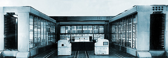
the Arrow machine was assembled on three main racks located in the form of the letter “P”. It was divided into an arithmetic device rack (right), an external drive rack and some auxiliary devices (left), and a random access memory and control rack (in the middle). The remote control, data input and output devices were located in the center. It allowed the operator to start and stop the machine, monitor the progress of the execution of program commands, and also enter into the random access memory and output from it individual numbers (data and commands) while the machine was stopped.
The device for preparing punch cards consisted of a keyboard device and an input punch. This allowed the operator using the keys to type on the punch cards the necessary information. After that, the prepared deck was removed from the input punch and placed in the data input device (reading) of the machine. Next, the data was entered into a random access memory (capacity up to 2048 words). The results of solving the problem were transmitted in the form of electrical signals to the output punch and there they were presented in the form of a system of holes on punch cards.
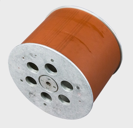
Magnetic tape from the computer "Strela", width 125 mm Polytechnic Museum
Machine performance reached 2000 three-address operations per second. The arithmetic device performed arithmetic operations (addition, subtraction, multiplication) and a number of additional operations (subtraction of the modules of numbers, shift of the number, allocation of part of the number, etc.).
The external drive had two blocks with a magnetic tape 125 mm wide and up to 100 m long. The numbers were located on the magnetic tape in groups in zones. That is, on each tape there could be 253 zones of various sizes, with up to 100,000 numbers on each tape. In total, an external drive could hold up to 200,000 numbers.

The principle of interaction of computer nodes (Journal "Knowledge-power" No. 7, 1956)
A feature of Strela was the flexibility of the command system. It was possible to create application libraries of various thematic areas with a volume of up to 100 million teams. This was accomplished thanks to the presence of several types of group arithmetic and logical operations, conditional transitions, replaceable standard programs, a system of control tests and organizing programs. Arrow was an example of original solutions in the element base. In this computer, the matrix implementation of the multiplication block on diodes was first realized. For the first time, an operational memory was used on 43 specialized storage cathode ray tubes. In addition, in the latest modification, a 4096-word magnetic drum unit with a rotation speed of 6,000 rpm has appeared.
Characteristics of the computer "Arrow"
Speed: up to 2000 three-address op / sec;
Main measure: 500 μs;
Addresses of teams: 12-bit;
Floating-point operations (35 - mantissa, 6 - order; 1 character);
Power consumption: 150 kW (75 kW - processor);
ROM: on semiconductor diodes with a capacity of 15 standard subprograms of 16 commands and 256 operands;
RAM: 20 μs;
Occupied area: 300 m 2 (of which 150 m 2 - processor);
Average useful time: 15-18 hours a day;
External memory: 2 tape drives with a capacity of 1.5 million words;
Element base: 6200 lamps and 60 000 semiconductor diodes;
Software: a library of routines, some of which are stitched in read-only memory.
On the computer "Strela" the first domestic techniques and programming methods were worked out, including in the operator form.
The memory of the Strela computer had a volume of 2048 cells of 43 digits, numbered from left to right from 0 to 42. As a result, the highest digit had number 0, and the lowest one 43. Access to the memory cells was carried out using 2-bit addresses. When the high order bit of the address was zero, access was made to the corresponding cell. A single value of this category was used when working with external devices and to access permanent memory.
Each memory location contained a number or command code. In the "zero" cells contained a zero value, respectively, the entry in this cell was ignored.
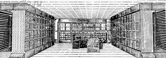
Sketch "Arrows"
To simplify the recording of information and addresses stored in memory, we used the octal number system.
The machine processed floating point numbers in binary and decimal systems. When written in machine format, the binary floating-point number consisted of the mantissa sign (bit 0), the absolute value of the mantissa (bits 1-35), the sign of the order (bit 36), and the absolute value of the order (bits 37-42).
The decimal floating point number also consisted of the sign of the mantissa (bit 0), the absolute value of the mantissa (bits 1-36), the sign of the order (bit 37) and the absolute value of the order (bits 38-42). Each decimal digit of the mantissa was recorded in binary decimal code, 4 bits per digit. But the order was preserved in binary form and could not exceed 19 in absolute value.
The value of the mantissa was always less than 1 and only its fractional part was stored in memory. The whole was considered equal to zero.
The external memory was made up of two bobbins of magnetic tape, each of which was divided into zones, where from 1 to 2048 numbers could be written. The zone of the first magnetic tape had octal numbers from 4001 to 4777, the second tape - from 5001 to 5777. Using special commands, information was read and written.
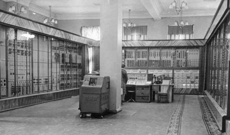
Computer "Arrow"
Commands were selected from memory and executed sequentially. The natural order of execution could be changed using the jump command.
The Arrow was a three-address computer (in each command code, three operand addresses were specified). The structure of the command code:
- first address (bits 0-11);
- second address (bits 12-23);
- third address (bits 24-35);
- control mark (rank 36);
- operation code (bits 37-42).
The control sign equal to 0 was ignored. When it was 1, then when the corresponding toggle switch on the control panel was turned on, the machine stopped after each execution of the command containing it.
The octal number system was used when writing commands. The command was written in a similar form:
0065 0231 1101 0 01
Checking of any conditions in the machine took place according to a special feature, usually denoted by the letter w . This feature was formed during the execution of certain commands (addition, comparison, etc.), and then used in the conditional branch command. If the sign was not formed by the team, then after execution it was reset to zero. Therefore, the conditional branch command should have been executed immediately after the formation of the analyzed characteristic.
In the table below, a denotes a cell that is determined by the address in bits 0-11 of the command code, b - cell, which is determined by the address in bits 12-23 of the command code, c - determined by the address in bits 24-35 of the command code.
Team designation table
In the period 1953-1957. The Strela computer was installed in seven key organizations of the Soviet Union. Namely: Department of Applied Mathematics of the Steklov Mathematical Institute (OPM MIAN USSR), Computing Center No. 1 of the USSR Ministry of Defense (Computing Center No. 1 of the USSR Ministry of Defense - military unit 01168), Almaz Research Institute (Almaz Scientific Research Institute), Computing Center of the Academy of Sciences of the USSR (Computing Center of the Academy of Sciences of the USSR), Research and Development Computing Center of Moscow State University named after MV Lomonosov (Research Center of Moscow State University), Nuclear Center "Arzamas-16" and Nuclear Center "Chelyabinsk-70". The machines were used for nuclear-space calculations and the solution of certain military tasks of national importance.
The first copy of the Strela computer was installed at the Steklov Mathematical Institute of the USSR Academy of Sciences (1953), the base Soviet institute for nuclear-space calculations. In the mid-1950s, a Soviet scientist in the field of applied mathematics and mechanics Mstislav Vsevolodovich Keldysh, who heads the institute, worked with the programming department to calculate the trajectories of artificial Earth satellites. Programs were supposed to provide round-the-clock processing of measurements of satellite paths. They were also used in the calculations of the flight of Yuri Alekseevich Gagarin. Also on the Strela computer, aerodynamic calculations of the Soviet passenger jet Tu-104 were carried out.

At the computer control panel Strela
One of the most important places for installing Strela computers was the computer center No. 1 of the USSR Ministry of Defense, since tasks of national importance were solved there. In 1950 Orbits of the first artificial Earth satellites and interplanetary space stations were calculated by car. The forces of programmers and mathematicians solved various information retrieval tasks for the main directorates and units of the USSR Ministry of Defense (Main Artillery Directorate, General Staff, Main Intelligence Directorate, Rear Logistics Directorate, Directorate of Ground Forces, etc.).
The seventh copy of the computer "Strela entered the Chelyabinsk-70 Nuclear Center" - the second center of the USSR for the development of nuclear weapons. A strong team of theoretical physicists, computer specialists, and scientists in the field of mathematical modeling worked in the center.
The creators of the Strela computer in 1954 received State Prizes of I, II, and III degrees. Yu.Ya. Bazilevsky was awarded the title Hero of Socialist Labor.
In the early 50's. B.I. Rameev began the development of a conceptual design of a digital electronic computer. After consideration by the technical advice of SKB-245, the scientist's project was approved. It is noteworthy that this happened on the first day the future chief designer of the machine Yu.Ya. went to work. Bazilevsky, appointed head of the department of digital machines SKB-245.
Bashir Iskandarovich Rameev (1918 - 1994) - Soviet scientist-inventor, developer of the first Soviet computers (Strela, Ural-1). Doctor of Technical Sciences. Laureate of the Stalin Prize.
Yuri Yakovlevich Bazilevsky(1912 - 1983) - Soviet scientist, chief designer of the Strela computer and the automated computer complex for the Dal-111 air defense system. He was a hero of Socialist labor, laureate of the Stalin Prize.
The Strela computer development team consisted of specialists: chief designer Yu.Ya. Bazilevsky, deputy. chief designer B.I. Rameeva, designers G.M. Prokudaeva A.M. Litvinova, D.A. Zhuchkova, A.V. Shileyko, main performers A.P. Tsygankina, NB Trubnikova, B.F. Melnikova, G.D. Monakhova, I.F. Lygina, L.A. Larionova, A.M. Larionova, E.T. Semenova and others.
Structure of SKB-24
In the late 40s - early 50s. SKB-245 was created on the basis of the Moscow factory of calculating and analytical machines (CAM). This abbreviation was deciphered as a special design bureau for the development and support of the manufacture of computer equipment and military control systems. The organization had 6 departments, which were designated by numbers (in connection with complete secrecy).
In the 1st division, secrecy of the developments was ensured and all structures were checked. Every day, employees of other departments were given suitcases with papers and stitched, numbered, sealed notebooks, which at the end of the working day were given up. In the 2nd department, work was carried out on analog computing tools. The development of the Strela computer was carried out by the 3rd department, under the leadership of Yu.Ya. Bazilevsky. The 4th department was mathematical, was under the direction of I.A. Gluzberg (and later - D.A. Zhuchkov). He was involved in the development of standard programs for Strela and conducted evaluations of operations. Material support lay on the 5th department. And the 6th - developed a differential analyzer, it was led by A.A. The poor thing. Over time, other departments were organized.
Development of "Arrows"
Work on the creation of "Arrows" was carried out with incredible enthusiasm. The interest of the employees was fueled by a kind of rivalry with ITMiVT of the USSR Academy of Sciences, where BESM was being developed at the same time.
Mikhail Avksentievich Lesechko - director of the SAM plant and head of SKB-245, gave all his inimitable talent to the organizer to work. For several nights, the equipment was mounted to cool the huge rooms, in which the assembled Strela devices were installed for debugging.
In the 6th department, which is directly involved in the development of Strela, there were several laboratories. B.I. Rameev led the laboratory responsible for the arithmetic device and the RAM unit, as well as the multiplication-division device. B. Zaitsev developed the addition-subtraction block. There was also a laboratory of G.M. Prokudaeva, who developed external storage devices on electronic tubes. External devices involved in the laboratory of Trubnikov.
In the photo the main creators of the machine “Strela”: B.I. Rameev, V.V. Alexandrov, Yu.Ya. Bazilevsky, D.A. Zhuchkov, A.P. Tsygankin, stand Yu.F. Shcherbakov, N.B. Trubnikov, G.M. Prokudaev, B.F. Melnikov, G.Ya. Markov and I.F. Lygin.
It is also worth noting that the development of Strela was held in record time. The project started at the beginning of the fiftieth year. At the end of 1951, the documentation was transferred to the CAM plant and already in 1952 the first copy of the machine was ready for debugging. Employees of SKB-245 developed not only logic, but designed, calculated all the elements.
In 1953, a working computer, Strela, was presented to the Commission on Stalin Prizes. She managed to get around Lebedev's BESM due to greater preparedness for industrial production. In addition, the development of Strela required less money. Therefore, the award was given by SKB-245.
Architecture and principles of work
About 6,000 electron tubes and several tens of thousands of semiconductor rectifiers (diodes) were used in Strela.
In the process,
the Arrow machine was assembled on three main racks located in the form of the letter “P”. It was divided into an arithmetic device rack (right), an external drive rack and some auxiliary devices (left), and a random access memory and control rack (in the middle). The remote control, data input and output devices were located in the center. It allowed the operator to start and stop the machine, monitor the progress of the execution of program commands, and also enter into the random access memory and output from it individual numbers (data and commands) while the machine was stopped.
The device for preparing punch cards consisted of a keyboard device and an input punch. This allowed the operator using the keys to type on the punch cards the necessary information. After that, the prepared deck was removed from the input punch and placed in the data input device (reading) of the machine. Next, the data was entered into a random access memory (capacity up to 2048 words). The results of solving the problem were transmitted in the form of electrical signals to the output punch and there they were presented in the form of a system of holes on punch cards.
Magnetic tape from the computer "Strela", width 125 mm Polytechnic Museum
Machine performance reached 2000 three-address operations per second. The arithmetic device performed arithmetic operations (addition, subtraction, multiplication) and a number of additional operations (subtraction of the modules of numbers, shift of the number, allocation of part of the number, etc.).
The external drive had two blocks with a magnetic tape 125 mm wide and up to 100 m long. The numbers were located on the magnetic tape in groups in zones. That is, on each tape there could be 253 zones of various sizes, with up to 100,000 numbers on each tape. In total, an external drive could hold up to 200,000 numbers.
The principle of interaction of computer nodes (Journal "Knowledge-power" No. 7, 1956)
A feature of Strela was the flexibility of the command system. It was possible to create application libraries of various thematic areas with a volume of up to 100 million teams. This was accomplished thanks to the presence of several types of group arithmetic and logical operations, conditional transitions, replaceable standard programs, a system of control tests and organizing programs. Arrow was an example of original solutions in the element base. In this computer, the matrix implementation of the multiplication block on diodes was first realized. For the first time, an operational memory was used on 43 specialized storage cathode ray tubes. In addition, in the latest modification, a 4096-word magnetic drum unit with a rotation speed of 6,000 rpm has appeared.
Characteristics of the computer "Arrow"
Speed: up to 2000 three-address op / sec;
Main measure: 500 μs;
Addresses of teams: 12-bit;
Floating-point operations (35 - mantissa, 6 - order; 1 character);
Power consumption: 150 kW (75 kW - processor);
ROM: on semiconductor diodes with a capacity of 15 standard subprograms of 16 commands and 256 operands;
RAM: 20 μs;
Occupied area: 300 m 2 (of which 150 m 2 - processor);
Average useful time: 15-18 hours a day;
External memory: 2 tape drives with a capacity of 1.5 million words;
Element base: 6200 lamps and 60 000 semiconductor diodes;
Software: a library of routines, some of which are stitched in read-only memory.
On the computer "Strela" the first domestic techniques and programming methods were worked out, including in the operator form.
Memory and information structure
The memory of the Strela computer had a volume of 2048 cells of 43 digits, numbered from left to right from 0 to 42. As a result, the highest digit had number 0, and the lowest one 43. Access to the memory cells was carried out using 2-bit addresses. When the high order bit of the address was zero, access was made to the corresponding cell. A single value of this category was used when working with external devices and to access permanent memory.
Each memory location contained a number or command code. In the "zero" cells contained a zero value, respectively, the entry in this cell was ignored.
Sketch "Arrows"
To simplify the recording of information and addresses stored in memory, we used the octal number system.
The machine processed floating point numbers in binary and decimal systems. When written in machine format, the binary floating-point number consisted of the mantissa sign (bit 0), the absolute value of the mantissa (bits 1-35), the sign of the order (bit 36), and the absolute value of the order (bits 37-42).
The decimal floating point number also consisted of the sign of the mantissa (bit 0), the absolute value of the mantissa (bits 1-36), the sign of the order (bit 37) and the absolute value of the order (bits 38-42). Each decimal digit of the mantissa was recorded in binary decimal code, 4 bits per digit. But the order was preserved in binary form and could not exceed 19 in absolute value.
The value of the mantissa was always less than 1 and only its fractional part was stored in memory. The whole was considered equal to zero.
The external memory was made up of two bobbins of magnetic tape, each of which was divided into zones, where from 1 to 2048 numbers could be written. The zone of the first magnetic tape had octal numbers from 4001 to 4777, the second tape - from 5001 to 5777. Using special commands, information was read and written.
Computer "Arrow"
Command system
Commands were selected from memory and executed sequentially. The natural order of execution could be changed using the jump command.
The Arrow was a three-address computer (in each command code, three operand addresses were specified). The structure of the command code:
- first address (bits 0-11);
- second address (bits 12-23);
- third address (bits 24-35);
- control mark (rank 36);
- operation code (bits 37-42).
The control sign equal to 0 was ignored. When it was 1, then when the corresponding toggle switch on the control panel was turned on, the machine stopped after each execution of the command containing it.
The octal number system was used when writing commands. The command was written in a similar form:
0065 0231 1101 0 01
Checking of any conditions in the machine took place according to a special feature, usually denoted by the letter w . This feature was formed during the execution of certain commands (addition, comparison, etc.), and then used in the conditional branch command. If the sign was not formed by the team, then after execution it was reset to zero. Therefore, the conditional branch command should have been executed immediately after the formation of the analyzed characteristic.
Instruction set
In the table below, a denotes a cell that is determined by the address in bits 0-11 of the command code, b - cell, which is determined by the address in bits 12-23 of the command code, c - determined by the address in bits 24-35 of the command code.
Team designation table
| Operation code | Team Name | Condition for setting the sign w | Actions performed by the machine on this command |
| 01 | Addition | s <0 | Algebraic addition of numbers a and b occurs , the sum is normalized and placed in cell c |
| 03 | Subtraction | c <0 | From a subtracted b |
| 05 | Multiplication | | c | > = 1 | The numbers a and b are multiplied |
| 04 | Subtraction of modules | c <0 | From the absolute value of a is subtracted absolute value b |
| 06 | Addition of orders | P ©> = 1 | In cell c , a number with the mantissa a and an order equal to the sum of the orders of the numbers a and b are written |
| 07 | Subtraction of orders | P ©> = 1 | In cell c , the number with the mantissa of the number a and the order equal to the difference in the orders of the numbers a and b are written |
| 10 | Transferring a number with a different number | P ©> = 1 | 1 In cell c , a number is written that has the absolute value a and the sign of the number b |
| 12 | Add numbers without rounding | c = 0 | The numbers a and b are algebraically added |
| eleven | Part selection | c = 0 | Logical AND operation is performed between cells a and b |
| thirteen | Formation | c = 0 | Logical OR operation is performed between cells a and b |
| 16 | Comparison | c! = 0 | Exclusive OR operation is performed between cells a and b |
| 14 | Shift in order | c = 0 | The contents of all the bits of cell a are shifted by P (b) bits |
| 17 | Checksumming | The numbers a and b are added over all digits with a cyclic transfer from the highest to the lowest | |
| 02 | Special addition | Address fields of cells a and b are added | |
| fifteen | Special subtraction | The address fields of cell b are subtracted from cell a | |
| 62 | Inverse Subtraction | Calculates n + 1 values that are inverse to the numbers in cell a and following it | |
| 63 | Square root extraction | c = 0 | Computes n + 1 square roots from the contents of cell a and following it |
| 64 | The calculation of the exponential function | Computes n + 1 exponential functions for cells a and following it | |
| 66 | Logarithm calculation | We compute n + 1 natural logarithms of the numbers contained in cells a and the following | |
| 67 | Sine calculation | The n + 1 sines of the numbers contained in cells a and the following are calculated | |
| 73 | Arc tangent calculation | The n + 1 arctangents of the numbers contained in cells a and the following are calculated | |
| 74 | Arcsine calculation | The n + 1 arcsines of numbers contained in cells a and the following are calculated | |
| 72 | Binary conversion of numbers | N + 1 numbers from cells a and the following are converted from the binary decimal system to binary and written to cells c | |
| 70 | Converting numbers to the decimal system | N + 1 numbers from cells a and the following are converted from binary to decimal and written to cells c | |
| 43 | Transfer numbers from tape to memory | Transfer n + 1 numbers from zone a of a magnetic tape to memory, starting from address c | |
| 46 | Transfer numbers from memory to tape | Transfer n + 1 numbers from punch cards to memory, starting at address c | |
| 44 | Transferring numbers from memory to punch cards | Transfer n + 1 numbers from memory, starting from address c , to punch cards | |
| 45 | Transfer numbers from memory to memory | Transfer n + 1 numbers from memory starting at address a to memory starting at address c | |
| 20 | Conditional jump of the first type | If, after performing the previous operation, w = 0 , then control is transferred to the command with address a . If w = 1 , the command with address b will receive control | |
| 27 | Conditional jump of the second type | If, after executing the previous command, w = 0 , then control is transferred to address a . If w = 1 , the command with address b will receive control . At the same time, a return command with a code is automatically written to cell c | |
| 25 | Tape feed | The area a of the magnetic tape is brought under the read head . Fields b and c of the command code are zero. This command is executed at the same time as the subsequent non-magnetic tape commands. | |
| 40 | Stop | The machine stops and issues the numbers a and b to the control panel . Field c of the command code is zero | |
| 26 | Comparison and stop when mismatch | The command differs from the command with operation code 16 in that, for w = 1 , it stops with the output of the numbers a and b |
The role of "Arrows" in the defense sector of the USSR
In the period 1953-1957. The Strela computer was installed in seven key organizations of the Soviet Union. Namely: Department of Applied Mathematics of the Steklov Mathematical Institute (OPM MIAN USSR), Computing Center No. 1 of the USSR Ministry of Defense (Computing Center No. 1 of the USSR Ministry of Defense - military unit 01168), Almaz Research Institute (Almaz Scientific Research Institute), Computing Center of the Academy of Sciences of the USSR (Computing Center of the Academy of Sciences of the USSR), Research and Development Computing Center of Moscow State University named after MV Lomonosov (Research Center of Moscow State University), Nuclear Center "Arzamas-16" and Nuclear Center "Chelyabinsk-70". The machines were used for nuclear-space calculations and the solution of certain military tasks of national importance.
The first copy of the Strela computer was installed at the Steklov Mathematical Institute of the USSR Academy of Sciences (1953), the base Soviet institute for nuclear-space calculations. In the mid-1950s, a Soviet scientist in the field of applied mathematics and mechanics Mstislav Vsevolodovich Keldysh, who heads the institute, worked with the programming department to calculate the trajectories of artificial Earth satellites. Programs were supposed to provide round-the-clock processing of measurements of satellite paths. They were also used in the calculations of the flight of Yuri Alekseevich Gagarin. Also on the Strela computer, aerodynamic calculations of the Soviet passenger jet Tu-104 were carried out.
At the computer control panel Strela
One of the most important places for installing Strela computers was the computer center No. 1 of the USSR Ministry of Defense, since tasks of national importance were solved there. In 1950 Orbits of the first artificial Earth satellites and interplanetary space stations were calculated by car. The forces of programmers and mathematicians solved various information retrieval tasks for the main directorates and units of the USSR Ministry of Defense (Main Artillery Directorate, General Staff, Main Intelligence Directorate, Rear Logistics Directorate, Directorate of Ground Forces, etc.).
The seventh copy of the computer "Strela entered the Chelyabinsk-70 Nuclear Center" - the second center of the USSR for the development of nuclear weapons. A strong team of theoretical physicists, computer specialists, and scientists in the field of mathematical modeling worked in the center.
The creators of the Strela computer in 1954 received State Prizes of I, II, and III degrees. Yu.Ya. Bazilevsky was awarded the title Hero of Socialist Labor.